InnovaPrep CP Select User manual

Copyright 2018, InnovaPrep LLC Patented https://www.innovaprep.com/patents
1

Copyright 2018, InnovaPrep LLC Patented https://www.innovaprep.com/patents
2
Table of Contents
1 PRODUCT OVERVIEW .............................................................................................................................................................. 4
1.1 PRODUCT DESCRIPTION ................................................................................................................................................................. 4
1.2 APPLICATIONS .............................................................................................................................................................................. 4
1.3 DEVICE SPECIFICATIONS ................................................................................................................................................................. 4
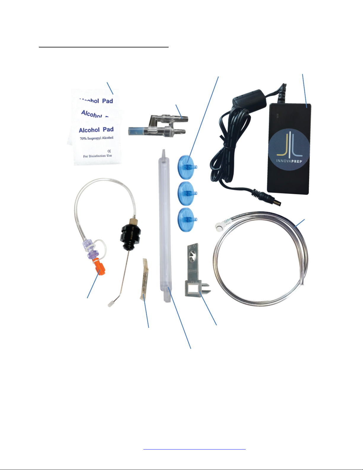
1.4 ACCESSORIES INCLUDED WITH THE CP SELECT .................................................................................................................................... 5
2 CONCENTRATING PIPETTE METHOD OF OPERATION ............................................................................................................... 7
2.1 CONCENTRATION PROCESS ............................................................................................................................................................ 7
2.2 WET FOAM ELUTION ..................................................................................................................................................................... 8
2.3 FOAM GENERATION ...................................................................................................................................................................... 8
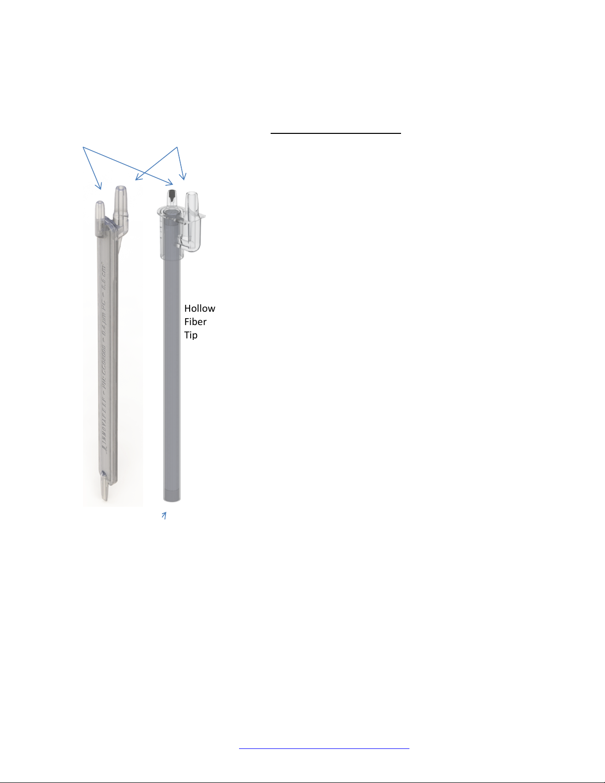
2.4 CP FILTER TIPS ............................................................................................................................................................................. 8
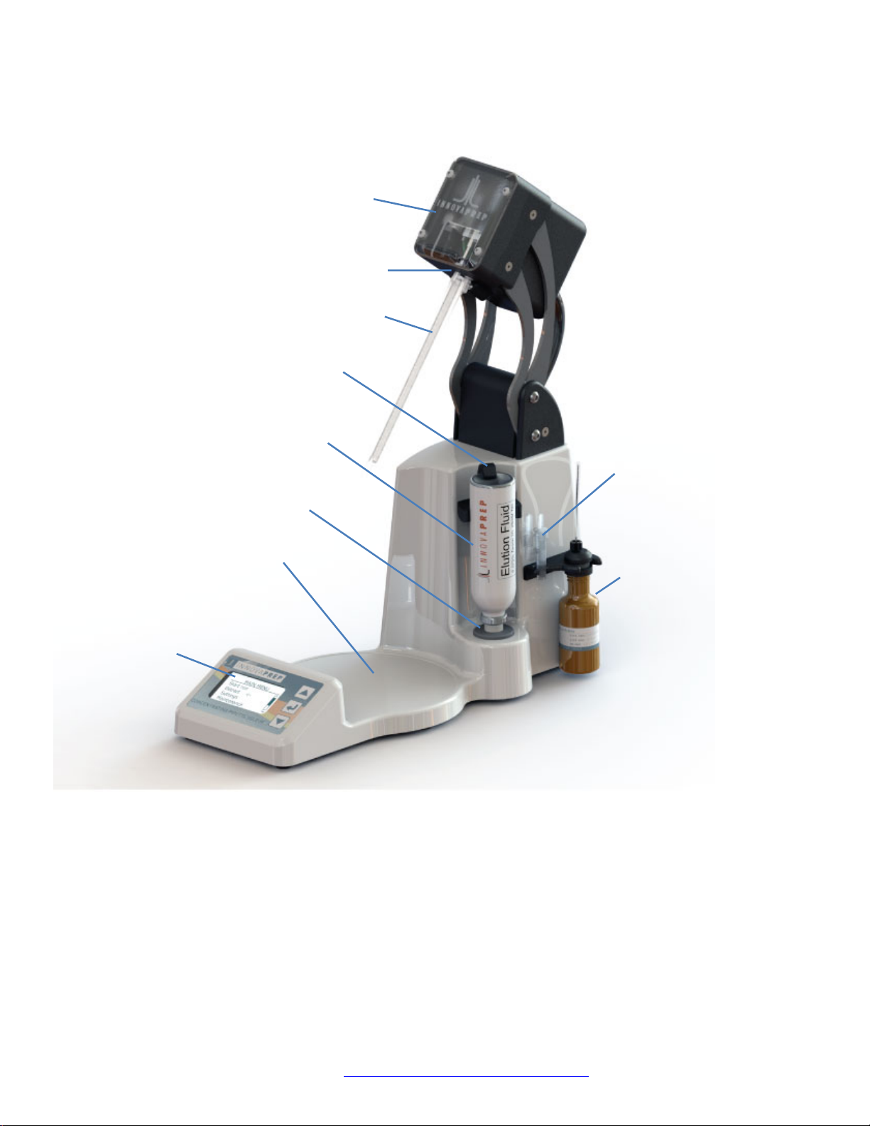
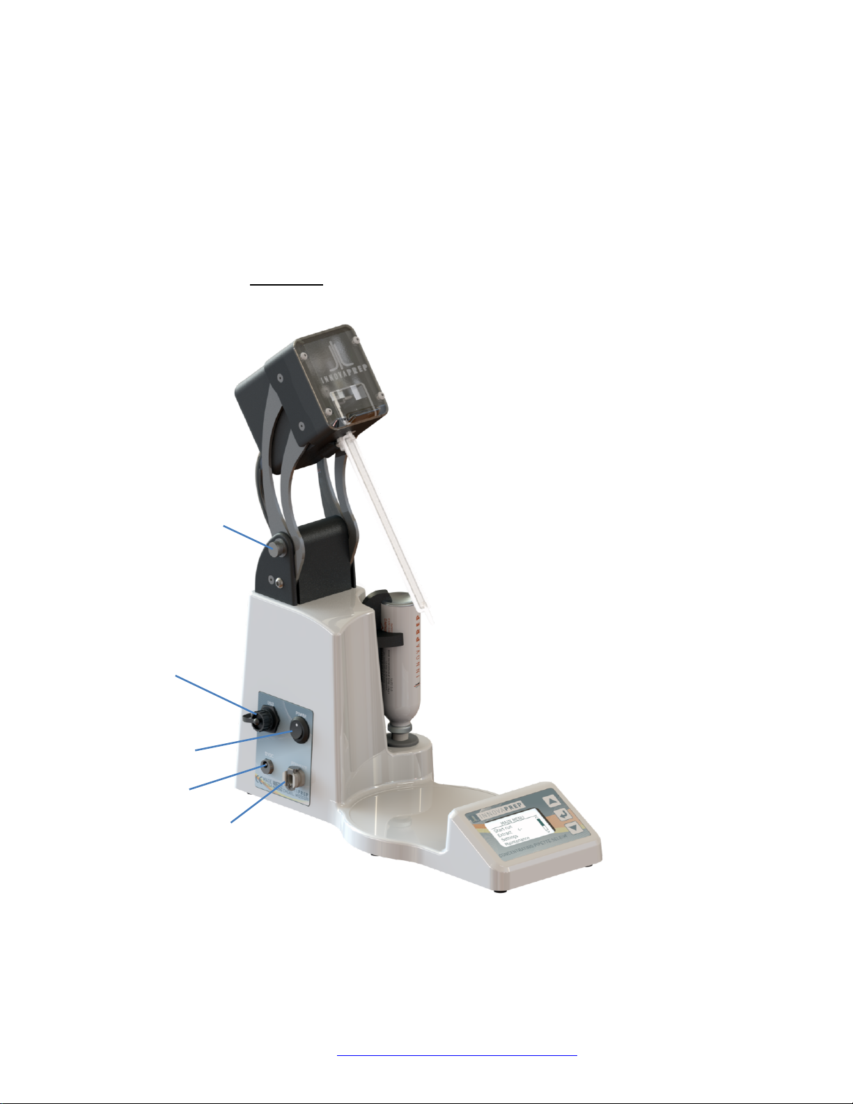
3 COMPONENTS OF THE CONCENTRATING PIPETTE ................................................................................................................. 10
4 INSTALLATION OF THE INSTRUMENT COMPONENTS ............................................................................................................. 13
4.1 INSTALLING THE POWER SUPPLY .................................................................................................................................................... 13
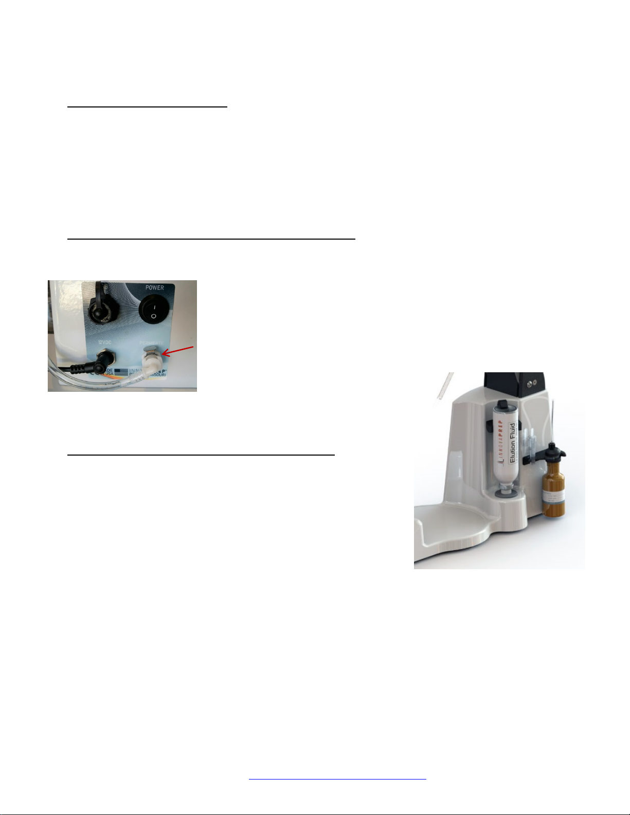
4.2 INSTALLING AND REMOVING THE PERMEATE LINE TUBING .................................................................................................................. 13
4.3 INSTALLING THE STORAGE FLUID AND FLUID ADAPTER ....................................................................................................................... 13
4.4 INSTALLING AND REMOVING AN ELUTION FLUID CANISTER ................................................................................................................. 14
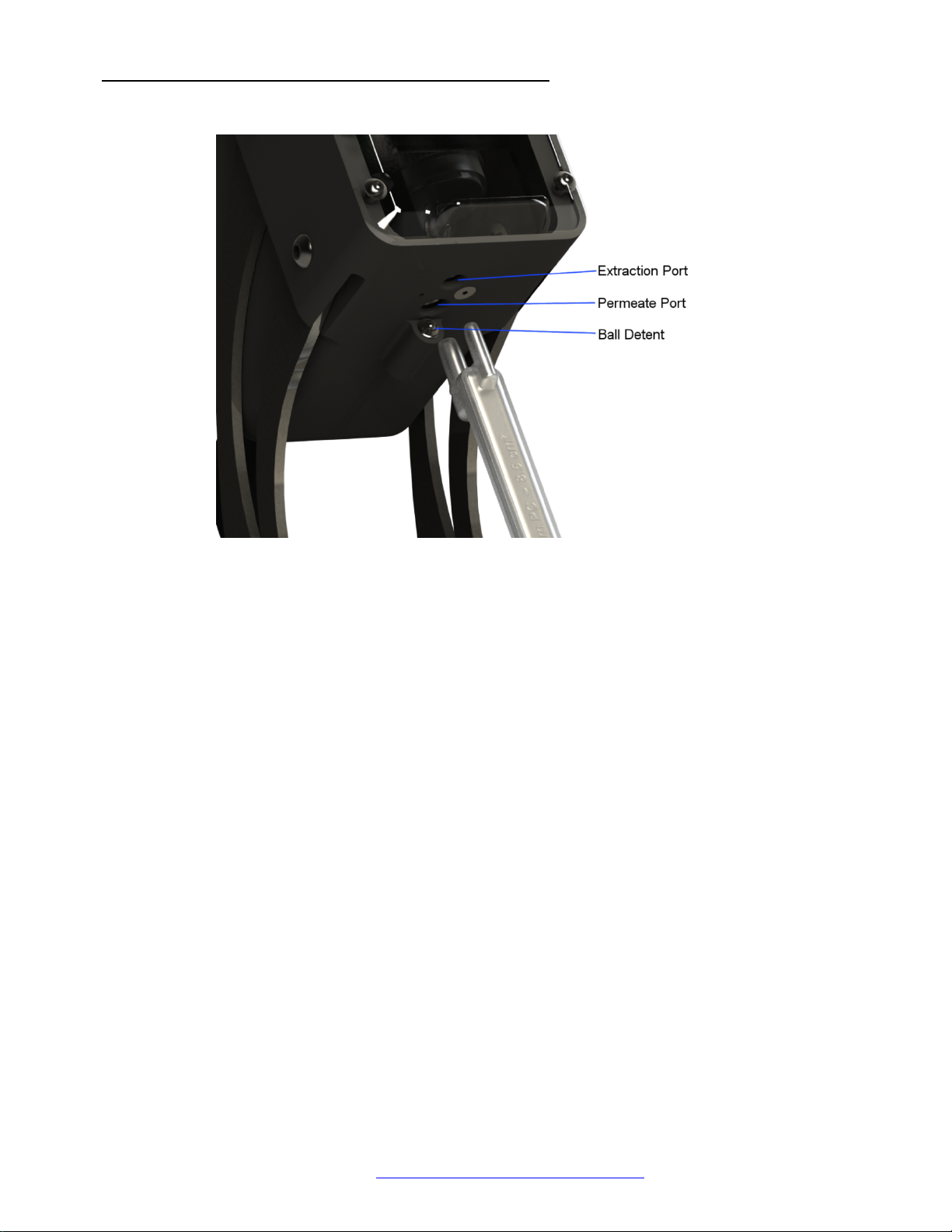
4.5 INSTALLING AND REMOVING CONCENTRATING PIPETTE TIPS ............................................................................................................... 15
5 NAVIGATING THE MENU ....................................................................................................................................................... 16
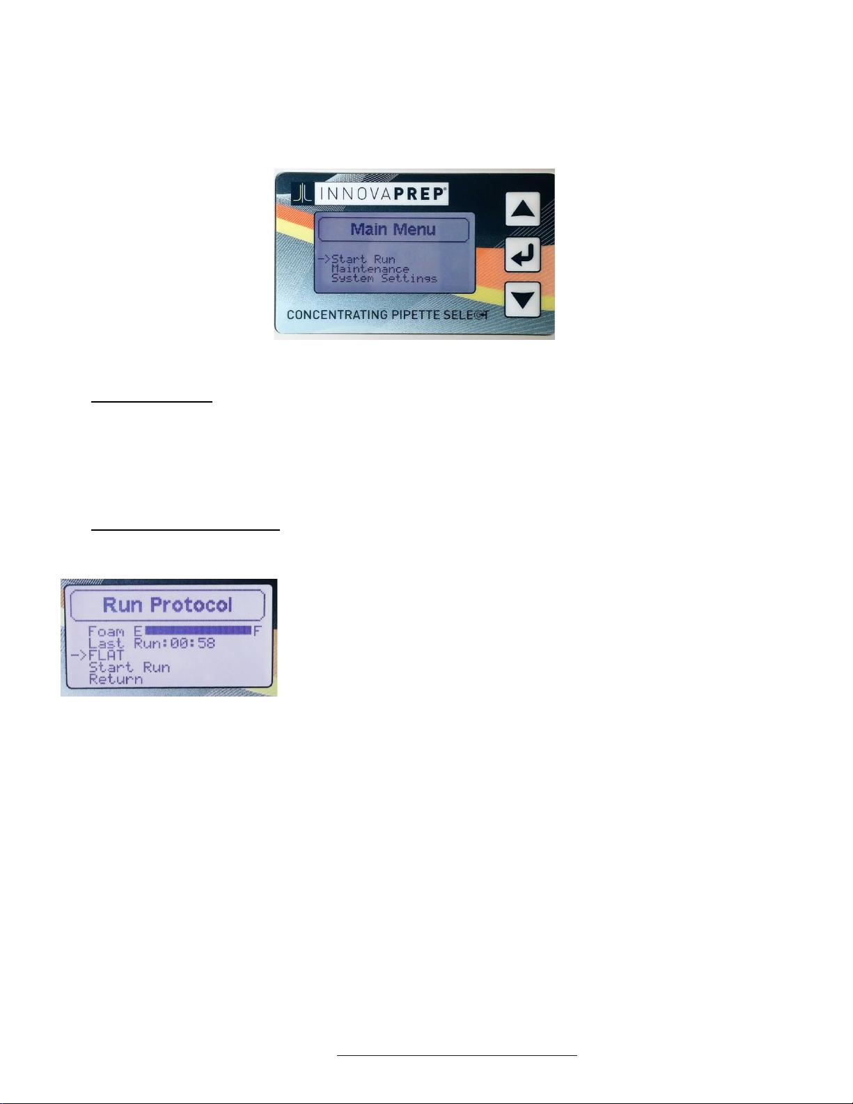
5.1 THE MAIN MENU ....................................................................................................................................................................... 16
5.2 THE RUN PROTOCOL MENU ......................................................................................................................................................... 16
5.3 THE MAINTENANCE MENU ........................................................................................................................................................... 17
5.4 THE INSTRUMENT SETTINGS MENU ................................................................................................................................................ 17
6 MAINTENANCE PROCEDURES ............................................................................................................................................... 18
6.1 STARTING UP THE INSTRUMENT FOR THE FIRST TIME ........................................................................................................................... 18
6.2 THE START UP PROCEDURE .......................................................................................................................................................... 19
6.3 THE SHUT DOWN PROCEDURE ...................................................................................................................................................... 19
6.4 PRIMING THE ELUTION FLUID ........................................................................................................................................................ 20
6.5 PREPARING THE INSTRUMENT FOR TRANSPORT OR SHIPMENT ............................................................................................................. 20
6.6 RECOMMENDED GENERAL MAINTENANCE FOR CP SELECT .................................................................................................................. 22
7 PERFORMING A SAMPLE CONCENTRATION RUN ................................................................................................................... 23
7.1 CONTROLLED COLLECTION OF PERMEATE ........................................................................................................................................ 23
8 CONCENTRATION RUN PROTOCOLS ...................................................................................................................................... 25
8.1 STD. OPTIONS ............................................................................................................................................................................ 25
8.2 ADV. OPTIONS ........................................................................................................................................................................... 25
8.3 DEFAULT CONCENTRATION RUN PROTOCOLS ................................................................................................................................... 26
8.4 SELECTING A PROTOCOL ............................................................................................................................................................... 27
8.5 CREATING A CUSTOM PROTOCOL ................................................................................................................................................... 27
8.6 EDITING A CUSTOM PROTOCOL ..................................................................................................................................................... 28
8.7 DELETING A PROTOCOL ................................................................................................................................................................ 28
8.8 PASSWORD PROTECTION .............................................................................................................................................................. 28
8.9 CONCENTRATING PIPETTE OPERATION CHECK LIST ............................................................................................................................ 29

Copyright 2018, InnovaPrep LLC Patented https://www.innovaprep.com/patents
3
9 TIPS AND SUGGESTIONS ....................................................................................................................................................... 30
10 SAFETY PRECAUTIONS ...................................................................................................................................................... 30
11 CONCENTRATING PIPETTE SUPPLIES ................................................................................................................................. 32
12 CHEMICAL COMPATIBILITY GUIDE .................................................................................................................................... 34
13 CUSTOM PROTOCOL RECORDS ......................................................................................................................................... 36
14 REVISION HISTORY ........................................................................................................................................................... 37

Copyright 2018, InnovaPrep LLC Patented https://www.innovaprep.com/patents
4
1 PRODUCT OVERVIEW
This Section contains a product description of the InnovaPrep Concentrating Pipette Select and a brief look at its
applications.
1.1 PRODUCT DESCRIPTION
The InnovaPrep Concentrating Pipette Select (CP Select), shown in Figure 1.1, quickly and efficiently concentrates particles
of interest from large liquid sample volumes into liquid volumes as small as 200 microliters (smaller volumes are attainable
in some applications). The CP Select uses a novel elution method to recover particles that have been captured onto a
disposable porous membrane filter with high recovery efficiencies.
FIGURE 1.1 INNOVAPREP CONCENTRATING PIPETTE SELECT
1.2 APPLICATIONS
The patented InnovaPrep concentration technology (US Patents 8,110,112; 8,584,535; 8,758,623; 9,593,359; 9,574,977;
9,738,918; D688,805; and other patents awarded and pending - see www.innovaprep.com/patents) has application
anywhere that enrichment of low concentrations of particles is needed. The primary area of application is for preparing
and concentrating particles of biological origin, including pathogens in liquid samples, for subsequent analysis by
traditional microbiological methods, such as plating, or with rapid molecular analytical devices.
1.3 DEVICE SPECIFICATIONS
Dimensions 13 in x 11 in x 7 in
Weight 8 lbs.
Input Power 100-240VAC 50/60 Hz, 1.5 Amps

Copyright 2018, InnovaPrep LLC Patented https://www.innovaprep.com/patents
5
Output 12VDC @ 3.0 Amps
1.4 ACCESSORIES INCLUDED WITH THE CP SELECT
An image and list, including part numbers, of the accessories that are provided with the CP Select is provided below.
FIGURE 1.2 ACCESSORIES
• AC Power Cord and Power Supply – North America and 12V Power Supply (HC03019, HC03093) - Power supply
for CP Select. See Section 4.1 (Power Cord available for North America (HC03019), EU (HC03208), and UK
(HC03209).
• Tubing Clip (HC08017) – Keeps permeate line secure to waste container.
• Permeate Line (HC08006) – Directs filtered fluid to waste container. See Section 4.2.
Alcohol Prep Pads
Maintenance Tip
11 µm Nylon Syringe
Filter 25mm
Power Cord
Permeate Line
Tubing Clip
Filterless Tip
Silicone Lubricant
Storage Fluid Adapter

Copyright 2018, InnovaPrep LLC Patented https://www.innovaprep.com/patents
6
• Silicone Lubricant (HC08535) – Used for required, periodic lubrication of O-rings in the Tip Interface Port. See
Section 4.5.
• Storage Fluid Adapter (HC08560) – Connects storage fluid bottle, required in daily Shut Down maintenance
procedure. See Section 4.3.
• Maintenance Tip (HC08005) – This reusable tip is inserted into the Tip Interface Port during the Start Up, Shut
Down and Prime maintenance procedures. DO NOT USE WITH THE ELUTE OR RUN PROTOCOL-DAMAGE CAN
OCCUR TO THE INSTRUMENT. See Section 6.
• Alcohol Prep Pads (HC08529) – Used for periodic cleaning of the tip and elution fluid ports.
• Filterless Tip (HC08524 - M) – Used for alternate cleaning and maintenance procedures. Also, for
troubleshooting and diagnostic procedures when consulting with InnovaPrep Technical Support Engineers.
Keep on hand.
• 11 µm Nylon Syringe Filter 25mm (HC08533) – Used for alternate cleaning and maintenance procedures.

Copyright 2018, InnovaPrep LLC Patented https://www.innovaprep.com/patents
7
2 CONCENTRATING PIPETTE METHOD OF OPERATION
The InnovaPrep concentration process uses dead-end filtration to capture particles onto the surface of a porous
membrane filter. A novel Wet Foam Elution™ process is then employed to wash the particles off of the membrane surface
into very small liquid volumes.
2.1 CONCENTRATION PROCESS
The concentration process of the CP Select requires single-use
Concentrating Pipette Tips (CPTs). The Pipette tips have internal filter(s)
made with either a flat membrane or a bundle of hollow fiber membranes.
The sample is drawn through the CPT, and once all the fluid has passed, it
elutes the concentrated particles through the sample port of the filter tip.
The sample is prevented from coming in contact with the instrument
fluidics, decreasing the need for between-sample decontamination and
eliminating cross-contamination or “carryover”.
The filters are hydrophilic, meaning that air is allowed to flow through only
when the membrane is dry. Once the filter has been wetted, the surface
tension of the liquid trapped in the pores of the membrane prevents air
(or any other gas) from passing through the membrane. Thus the CPTs
cannot be re-used since air trapped inside the housing cannot be pulled
through the filter prior to processing a second sample.
The concentration process is performed in the following steps:
1. The main pump draws a vacuum on the Permeate Port. The air inside
the filter housing is drawn out and the liquid sample is pulled up through
the Sample Port.
2. As the sample is drawn through the filter, particles larger than the
chosen membrane pore size are captured on the pores; while liquids,
dissolved solids and particles smaller than the chosen pore size pass
through the filter and into the permeate.
3. Once the sample container is empty, air is drawn up behind the
liquid and the membrane “locks up”; leaving only the target particles on
the membrane and ending the run.
4. When the user performs an elution, InnovaPrep’s patented Wet Foam Elution™ process is utilized. The Permeate
Port valve closes and the elution valve opens, allowing the foam to enter the Elution Port. The foam travels
tangentially down the surface of the membrane as it washes the particles from the surface. The concentrated
sample is then pushed out of the sample port into a cuvette or other container where the foam quickly breaks
back down into a small liquid volume.
Elution Port
Permeate Port
Flat
Membrane
Tip
Hollow
Fiber
Tip
FIGURE 2.1 FLAT AND HOLLOW FIBER
CONCENTRATING PIPETTE TIPS

Copyright 2018, InnovaPrep LLC Patented https://www.innovaprep.com/patents
8
2.2 WET FOAM ELUTION
The Wet Foam Elution process is much more efficient than liquid rinsing for the following reasons:
Volume Expansion
When rinsing a filter with liquid, most of the liquid volume is used to fill the dead space inside the filter housing; or
inner bore of the membrane for hollow fiber tips. Thus, only a small portion of the fluid is actually in contact with the
filter surface. This can be minimized to an extent by reducing the cross-sectional area of the fluid path across the filter,
but a large portion of the liquid is still underutilized. Foam, however, is 80-90% gas, which fills the empty space without
contributing to the final sample volume.
Increased Viscosity
Liquid has a tendency toward “channeling” when flowing across a surface; that is, there is an area of high flow in the
center of the fluid path while the portion of flow in contact with the filter surface is much slower. The higher viscosity
of foam prevents channeling and creates a more uniform flow across the filter surface.
Bubble Dynamics
The micro-bubbles in the foam behave as deformable solids. As they travel across the surface of the filter they move
as a rigid body with a narrow lubricating layer, effectively squeegeeing the particles off of the surface.
Exfoliating Action
As the micro-bubbles in the foam impact against each other and burst, the turbulence and energy produced helps to
lift particles that are adhering to the membrane.
2.3 FOAM GENERATION
The Wet Foam Elution™ process requires very specific high-quality foam in order to be effective. The elution fluid is
composed of water, a low concentration surfactant (usually less than 0.1%), and a pH buffer. This solution is carbonated
with carbon dioxide (CO2) gas. During the elution process, the fluid passes through a valve to a low pressure environment,
causing the dissolved CO2 to expand and come out of solution to form microbubbles. These micro-bubbles increase the
volume of the fluid sixfold or more.
An additional benefit of Wet Foam Elution is the clean buffer exchange. In many situations, the starting sample matrix is
not the most desirable for the chosen analysis method. Wet Foam Elution allows the user to select the fluid that the
particles will be suspended in after concentration, which reduces inhibition and maximizes the chances of detection.
2.4 CP FILTER TIPS
For selecting the proper CPT please refer to the filter selection matrix presented in Table 2.1.

Copyright 2018, InnovaPrep LLC Patented https://www.innovaprep.com/patents
9
TABLE 2.1 CONCENTRATING PIPETTE SELECTION GUIDE
Part Number
Filter Tip
Media Type
Pore Size
Membrane
Surface Area
cm2
Input Sample
Volume (Varies
by Matrix)
Final Concentrated
Sample Volume
(User Selectable)
Processing Rate
(Varies by Matrix)
mL/min
Notes
CC08000-10
Flat Membrane
Polycarbonate
Track Etch
0.4 μm
8.5
Up to 1 Liter*
200 - 1000 μL
Up to
100 mL /min.
Recommended for concentrating bacteria,
whole cells, spores, pollen, and parasites from
food and beverage matrices or samples
containing proteins and polysaccharides
CC08001-10
Flat Membrane
Polyethersulfone
0.1 μm
8.5
Up to 1 Liter*
200 - 1000 μL
Up to
100 mL /min.
Recommended for concentrating bacteria,
whole cells, spores, pollen, and parasites from
environmental samples
CC08018-10
Hollow Fiber
Polysulfone
0.45 μm
98
Up to 5 Liters*
150 - 1000 μL
Up to
150 mL/min
Recommended for concentrating bacteria,
whole cells, spores, pollen, and parasites from
high fouling matrices
CC08022-10
Hollow Fiber
Polysulfone
0.2 μm
98
Up to 5 Liters*
150 - 1000 μL
Up to
150 mL/min
Recommended for concentrating bacteria,
whole cells, spores, pollen, and parasites from
all sample types
CC08020-10
Hollow Fiber
Polysulfone
0.05 μm
98
Up to 3 Liters*
150 - 1000 μL
Up to
90 mL/min
Recommended for virus concentration. The
addition of Tween 20 to the sample is
recommended to aid recovery efficiency (add
10% solution of Tween 20 in a 1/100 ratio to
the sample)
CC08003-10
Hollow Fiber
Polysulfone
Ultra -
Filtration
98
Up to 500 mL*
150 - 1000 μL
50 mL/min with
Tween 20
* With regards to starting sample volume, it is recommended that the entire sample should be processed within 30 minutes. It has been observed that there is a reduction
in the recovery when processing times exceed 30 minutes. The recommended upper-end run volume as shown in the concentrating pipette tip selection guide and time of
30 minutes is a general recommendation and may be dependent on sample matrix and target organism. See Section 10 for full part number list.

Copyright 2018, InnovaPrep LLC Patented https://www.innovaprep.com/patents
10
3 COMPONENTS OF THE CONCENTRATING PIPETTE
The following Section describes the components of the InnovaPrep Concentrating Pipette Select.
FIGURE 3.1 CONCENTRATING PIPETTE COMPONENTS - RIGHT SIDE
Fluidics Head – This component contains the bulk of the fluidic components in the instrument. The Head can be raised
and lowered to position the Concentrating Pipette Tip in the sample container. LED lights in the head will glow blue
when the instrument is on, red when the instrument is concentrating and green when the instrument is eluting.
Tip Interface Ports – This is the point of installation for the consumable Concentrating Pipette Tips. The foam Elution
Port is in front where the foam is introduced into the tip at the time of elution. The sample fluid exits the rear Permeate
Port during a sample run.
Concentrating Pipette Tip (CPT) – This consumable component is the only part of the instrument that will come in
contact with the sample.
Canister Latch – This latch holds the Elution Fluid canister in place.
Fluidics Head
Tip Interface Ports
Single-use Pipette Tip
Sample Platform
Control Panel
Canister Latch
Elution Fluid (Foam) Canister
Canister Interface Port
Storage Fluid w/
Adapter Set
Maintenance Tip

Copyright 2018, InnovaPrep LLC Patented https://www.innovaprep.com/patents
11
Elution Fluid (Foam) Canister – Each canister contains enough elution fluid for up to 30 elutions.
Maintenance Tip – This reusable component is installed in the Tip Interface Port during the Start Up, Shut Down, and
Prime Maintenance Protocols. It is stowed on the bracket located on the right side of the instrument. DO NOT USE
WITH THE ELUTE OR RUN PROTOCOL - DAMAGE CAN OCCUR TO THE INSTRUMENT.
Storage Fluid with Adapter – This assembly is for use with the Shut-Down protocol. It conveniently stows on the
bracket located on the right side of the instrument.
Canister Interface Port – This spring-loaded port keeps the proper pressure on the valve of the fluid canister
(sometimes referred to as Can); it contains a check valve, which keeps the instrument pressurized when changing
canisters. The Storage Fluid Adapter also interfaces with this port during the Shut Down Maintenance Protocol.
Control Panel – The LCD display is navigated by the Up ( ▲ ), Down ( ▼ ), and Enter (
⏎
) keys. Certain menus may
also be entered by pressing and holding Enter (
⏎
) down for approximately 1 second.
Sample Platform – The sample container is placed here during sample processing.
Tension
Knob
USB Port
Power Switch
12V DC Power
Jack
Permeate Line Port
FIGURE 3.2 INSTRUMENT COMPONENTS – LEFT SIDE

Copyright 2018, InnovaPrep LLC Patented https://www.innovaprep.com/patents
12
Tension Knob – This knob is used to adjust the tension on the positioning arms for the Fluidics Head.
USB Port – A standard 'Micro-B' USB cable can be connected to the instrument from a computer to download periodic
software updates from the manufacturer.
12V DC Power Jack – Port for the included power supply.
Power Switch – The up position ( | ) turns the instrument on and the down position ( ¡ ) turns the instrument off.
Permeate Line Port – This quick connect fitting is where the filtered fluid (Permeate) exits the instrument. This port is
valved to prevent fluid from being pumped out without the permeate tubing attached.

Copyright 2018, InnovaPrep LLC Patented https://www.innovaprep.com/patents
13
4 INSTALLATION OF THE INSTRUMENT COMPONENTS
This Section will guide the user through setting up the instrument.
4.1 INSTALLING THE POWER SUPPLY
Plug the power cord and power supply together, plug the power supply into the 12VDC port on the side of the unit, then
plug the power cord into an available power outlet. It is not necessary to select the correct voltage; the sensor accepts
line voltage of 100 to 240 VAC, 50-60 Hz, single phase. The connection is self-regulating. WARNING: DO NOT USE ANY
POWER SUPPLY OTHER THAN THE ONE SUPPLIED WITH THE CP SELECT INSTRUMENT-DOING SO MAY CAUSE DAMAGE TO
THE INSTRUMENT AND VOID THE WARRANTY. (NOTE: THE POWER SUPPLY FOR THE PREVIOUSLY RELEASED CP - 150
CONCENTRATING PIPETTE INSTRUMENT IS NOT COMPATIBLE WITH THE CP SELECT)
4.2 INSTALLING AND REMOVING THE PERMEATE LINE TUBING
Included with the instrument is a Section of clear PVC tubing with a right angle quick connect fitting; this is the permeate
line tubing. To install the Permeate Line, first make sure that the metal button on the Permeate Port is pushed down on
the instrument. Then, insert the quick connect fitting on the Permeate Line into the
Permeate Port. When the fitting is fully seated the metal button will pop up, thus
locking it in place. Place the open end of the permeate line tubing into a waste
container of adequate volume relative to your sample volume.
To remove the Permeate Line, simply
press the metal button on the
Permeate Port and it will be released.
4.3 INSTALLING THE STORAGE FLUID AND FLUID ADAPTER
A daily Shut-down Maintenance Procedure is described in Section 6.3. The
procedure requires the use of the following items:
• Storage Fluid (HC08558)
• Reusable Storage Fluid Adapter (HC08560)
• Reusable Maintenance Tip (HC08005)
These items are conveniently stowed on a bracket on the right side of the
instrument as pictured at right in Figure 4.2. Figure 4.4, below, provides a
closer view of the Storage Fluid and Storage Fluid Adapter.
To install the Storage Fluid Adapter, remove the orange rubber cap (save for later use-used for transport and shipping)
from the Canister Interface Port and clean the port using an Alcohol Prep Pad. Remove the sealed cap from the Storage
Fluid bottle, and install the metal sipper tube portion of the Fluids Adapter into the bottle. The metal portion of the
assembly can be adjusted up or down in the bung to reach the bottom of the fluid bottle by loosening the fitting located
on the top of the bung. The Bung can now clip onto the bracket as shown, with the Fluids Adapter tubing clipped into the
bracket behind the bottle. The Maintenance Tip also stows on the bracket in the 1st position. See Section 6 for detailed
instructions for use.
FIGURE 4.2 STORAGE FLUID BRACKET
FIGURE 4.1 PERMEATE LINE
INSTALLATION

Copyright 2018, InnovaPrep LLC Patented https://www.innovaprep.com/patents
14
4.4 INSTALLING AND REMOVING AN ELUTION FLUID CANISTER
To install an elution fluid canister into the instrument, first hold the canister with the valve
pointing down. Then place the canister valve into the Canister Interface Port located on
the right side of the instrument. Now press the canister down and hook the edge under
the Canister Latch as shown in Figure 4.5.
REMOVING A FLUID CANISTER
To remove an Elution Fluid Canister, push down on the top of the canister pulling it away
from the instrument to unlatch.
When the instrument is new, the elution fluid canister valve will tend to stick in the Canister
Interface Port. Simply grab the canister with your hand and press your thumb against the
Canister Latch to leverage it up and out of the Canister Interface Port.
If a canister is removed before it is completely empty, a small amount of fluid (approximately 100 µL) may be expelled
from the can, this is normal.
The Canister Interface Port is the first place where contamination can enter the instrument's fluidics. Never let dust or dirt
enter the port and use good lab practices to prevent bacterial contamination. This would include not touching the stem
of the Elution Fluid Canister, the storage fluid interface fitting, or the Canister Interface Port with fingers or other non-
sterile objects. Protect the Canister Interface Port from contaminants by leaving the Storage Fluid Adapter connected to
the port when the instrument is not in use. Utilize the protective orange cap (HC03173) included with the unit for long
term storage. Clean the Canister Interface Port using an Alcohol Prep Pad prior to installing a new elution fluid canister.
FIGURE 4.4. STORAGE FLUID AND
STORAGE FLUID ADAPTER
FIGURE 4.3 STORAGE FLUID AND STORAGE FLUID
ADAPTER STOWED ON CP SELECT BRACKET
FIGURE 4.5 INSTALLING AND
REMOVING FLUID CANISTERS

Copyright 2018, InnovaPrep LLC Patented https://www.innovaprep.com/patents
15
4.5 INSTALLING AND REMOVING CONCENTRATING PIPETTE TIPS
Figure 4.6 shows how the CPT ports are aligned with the ports in the Fluidics Head.
FIGURE 4.6 TIP INTERFACE PORT DETAIL
To install a CPT, first raise the Fluidics Head all the way up. The two ports on the top of the CPT are different sizes; the
larger port is the permeate port facing the rear of the instrument. The CPT can only be installed one way and should slide
easily up into the ports on the underside of the Fluidics Head. When the CPT is fully seated, you should feel it "click” into
place. You can also verify that that the CPT is fully seated by looking through the clear fluidics manifold.
The rubber O-rings in these ports should be occasionally lubricated with the Silicone lubricant (item HC08535-20), provided
with the instrument, to maintain a tight seal. With a gloved finger, rub a very thin layer of lubricant on both ports of the
Maintenance Tip periodically (monthly) to ensure the O-rings remain flexible and leak free.
To remove the CPT, grasp it with your hand then use your thumb to press up on the underside of the Fluidics Head. The
"thumbs up" technique eliminates the need to hold the Fluidics Head with your free hand while you pull down on the CPT.

Copyright 2018, InnovaPrep LLC Patented https://www.innovaprep.com/patents
16
5 NAVIGATING THE MENU
This Section will guide you through the instrument's LCD menu instrument on the Control Panel. The three keys on the
right side of the Control Manual (symbols for Up ( ▲ ), Down ( ▼ ), and Enter (
⏎
), as shown in Figure 5.1) are used to
navigate the menu.
5.1 THE MAIN MENU
When the instrument is first turned on, a Welcome screen will be displayed as soon as the unit boots up (about 5 seconds).
Press Enter (
⏎
) to continue to the Main Menu screen.
The Main Menu consists of three selections: Start Run, Maintenance, and Instrument Settings.
5.2 THE RUN PROTOCOL MENU
Selecting Start Run from the Main Menu will display the Run Protocol screen. This screen displays:
Foam Volume Gauge (E = empty / F = full)
Last Run process time (mm:ss)
Name of the selected concentration run protocol (defaults to FLAT)
Start Run
Return
• Selecting the named protocol (FLAT) will navigate to the Protocol Setup screen where another protocol can be
selected, created (see Section 8.5 Creating and Saving a Concentration Run Protocol), or deleted. There are three
protocol options that have been preprogrammed by the factory named FLAT, HOLLOW, and ULTRA. These have
been named according to the three main types of CPTs available for use with the instrument: FLAT for use with
the flat CPTs (items CC08000 and CC08001), HOLLOW for use with the hollow fiber tips (items CC08018, CC08022,
CC08020), and ULTRA for use with the ultrafilter tips (item CC08003). See Table 2.1 CPT Selection Guide for a full
description.
• Selecting Start Run on the Run Protocols screen will immediately start the sampling process using the sample
protocol notated above.
• Return will lead back to the Main Menu.
Up ( ▲ )
Enter (
⏎
)
Down ( ▼ ),
FIGURE 5.1 MAIN MENU DISPLAY
FIGURE 5.2 RUN PROTOCOL
DISPLAY

Copyright 2018, InnovaPrep LLC Patented https://www.innovaprep.com/patents
17
5.3 THE MAINTENANCE MENU
Selecting Maintenance from the Main Menu will display instrument procedures (see Section 6 Maintenance
Procedures):
Start Up
Shut Down
Prime
Elute
Return
• Selecting Start Up will take the user through a series of prompts for the daily Start Up procedure (see Section
6.2 Start Up Procedure).
• Selecting Shut Down will take the user through a series of prompts for the daily Shut Down procedure (see
Section 6.3 Shut Down Procedure).
• Prime is for priming the elution fluid lines when a new elution fluid canister is installed in the unit. This
ensures that there is no air in the fluid path (see Section 6.4 Priming the Elution Fluid).
• Elute performs a foam elution according to the current instrument settings. This can be used at any time to
test the elution settings (see Section 8 The Elute Function).
• Return will lead back to the Main Menu.
5.4 THE INSTRUMENT SETTINGS MENU
There are seven instrument settings. A description of each are listed below:
• Beep volume changes the volume of the beeps that occur at the end of concentration cycles and elutions.
The four options are low, med., high, and off. Default = low
• Power LED turns the blue LED light in the Fluidics head on and off. Default = on
• Run LED turns the flashing red LED light in the Fluidics head on and off. Default = on
• Elute LED turns the flashing green LED light in the Fluidics head on and off. Default = on
• Set Password allows the user to set a password that must be entered before a custom protocol can be
created, modified, or deleted.
• Protocol allows the user to set the instrument to standard (Std) or advanced (Adv) options. If set to Std, the
user will have access to two standard set points - Valve Open and Pulse Count. If set to Adv, the user will
have access to 11 advanced settings during Protocol Creation. Once set, the options are accessed in the
Protocol Setup menu under Create Protocol. Default = Std
• Fluid Gauge turns the Elution Fluid Volume gauge on and off. Default = on
• Return will return you to the Options menu.
FIGURE 5.3 MAINTENANCE DISPLAY

Copyright 2018, InnovaPrep LLC Patented https://www.innovaprep.com/patents
18
6 MAINTENANCE PROCEDURES
This Section will guide the user through the daily maintenance procedures including how to perform the Start Up and Shut
Down routine and priming the elution fluid. Section 6.1, below, provides a Start Up procedure for the first time the
instrument is used. Sections 6.2 and 6.3 provide the standard Start Up and Shut Down procedures which should be
followed at the start and end of each day of use. Sections 6.4 and 6.5 describe the Prime and Elute functions. The
operation check list below, and also found in Section 8.9, should be performed before the first use and can be performed
any time if there is a question about the function of the instrument.
To ensure that the Concentrating Pipette was not damaged during shipping, the following procedure can be performed.
1. Check for pressure leak:
a. Insert Maintenance Tip, Elution Fluid Canister and Permeate Line. Insert the end of the Permeate Line in
water and Start Run.
b. Check that no bubbles are seen exiting the Permeate Line between 4 and 10 seconds.
2. Check Canister Interface Port and prime CP unit:
a. Insert an Elution Fluid Canister into the Canister Interface Port and check for leaks.
b. From the Main Menu select Maintenance>Prime and follow the menu prompts. Check for production
of foam.
c. Remove Elution Fluid Canister.
d. Ensure there is no leakage from the Canister Interface Port.
e. Re - install Elution Fluid Canister.
3. Check flow rate:
a. From the Run Protocols menu select FLAT.
b. Using the Filter-less Tip provided with the instrument, perform a 200 mL distilled water concentration
run. The run time should not exceed 1:30.
c. Perform an elution.
4. Look inside the head of the unit and check for any visible fluid leaks or moisture inside the head.
Failure in any of the above tests indicates a return of the Concentrating Pipette for repair may be necessary.
6.1 STARTING UP THE INSTRUMENT FOR THE FIRST TIME
Step 1 – Remove the instrument from the box and packaging. Place on a clean surface and
remove the orange rubber cap from the Canister Interface Port.
Step 2 – Follow instructions for installation of the instrument components as described in
Section 4: Install Power Supply (Section 4.1) and Permeate Line (Section 4.2), and stow the
Storage Fluid and Adapter in the bracket on the right side of the instrument (Section 4.3).
Step 3 – Power instrument on.
FIGURE 6.1
MAINTENANCE TIP

Copyright 2018, InnovaPrep LLC Patented https://www.innovaprep.com/patents
19
Step 4 – Advance to the Main Menu by pressing Enter (
⏎
) on the control panel.
Step 5 – Select Maintenance>Prime
Step 6 – Follow the menu prompts: Place the Maintenance Tip into the Tip Interface Port as
shown in Figure 6.1 using the same procedure described in Section 4.5 for installing a CPT.
Select Continue.
Step 7 – Follow the menu prompt: Place Foam Can (Elution Fluid Canister) Into Position. Use
the installation instructions described in Section 4.4. Make sure the open end of the
permeate line is secured in a waste container. Select Continue. The instrument will purge
elution fluid from the canister through to the permeate. The instrument is now ready for use.
6.2 THE START UP PROCEDURE
Biological contaminants or salts from evaporated elution fluid can be damaging to the instrument if they are allowed to
produce particles large enough to clog the fluid path. The daily Shut Down and Start Up Maintenance Protocol is used to
clean and flush contaminants from the fluid path of the instrument.
The Start Up Procedure is accessed by selecting Main Menu > Maintenance > Start Up. The selection will guide the user
through a series of prompts. The prompts assume the user followed the Shut Down procedure, following the last
instrument use, which instructs the user to leave the Storage Fluid Adapter installed in the Canister Interface Port.
Step 1 – Ensure the required instrument components have been installed: Power Supply (Section 4.1), Permeate
Line (Section 4.2), Storage Fluid and Adapter (Section 4.3).
Step 2 – Power instrument on. Advance to the Main Menu by pressing Enter (
⏎
) on the control panel.
Step 3 – Select Maintenance>Start Up
Step 4 – Follow the menu prompt: Place the Maintenance Tip into Tip Interface Port as shown in Figure 6.1 using
the same procedure described in Section 4.5 for installing a CPT. In practice, the Maintenance Tip should already
be in position in most cases, because it should be in place during periods of non - use. Select Continue.
Step 5 – Follow the menu prompt: Remove Storage Fluid Line from Can Interface Port. Cap the adapter fitting
and stow the tube set in the notch on the storage bracket as shown in Figure 4.3. Double check that the open
end of the permeate line is secured in a waste container. Select Continue. The instrument will purge the storage
fluid from the instrument’s fluidics. NOTE: DO NOT INSTALL AN ELUTION FLUID CANISTER UNTIL PROMPTED TO
DO SO IN STEP 6.
Step 6 – Follow the menu prompt: Place Foam Can into Position (see Section 4.4). Select Continue. The
instrument will prime the foam line with elution fluid. The instrument is now ready for use.
6.3 THE SHUT DOWN PROCEDURE
It is important to perform the Shut Down procedure at the end of each day of operation for the maintenance of the
instrument. The Shut Down procedure performs two important functions, instrument decontamination and the
prevention of salt crystals forming in the fluidics due to evaporation of the elution fluid.
Step 1 – From the Main Menu select Maintenance>Shut Down.

Copyright 2018, InnovaPrep LLC Patented https://www.innovaprep.com/patents
20
Step 2 – Follow the menu prompt: Remove Foam Can. Select Continue.
Step 3 – Follow the menu prompt: Place Maintenance Tip into Tip Port. Select Continue.
Step 4 – Follow the menu prompt: Insert Storage Fluid Line into Can Port. To do so, remove the orange cap from
the Storage Fluid Adapter and insert the tube fitting into the Canister Interface Port by pressing it firmly in place
(the fitting will only go in about 1/8th - inch). Select Continue. The fluid will rinse through the instrument to the
permeate.
Step 5 – Follow the menu prompt: Power Off Unit or Restart. Leave the Maintenance Tip and Storage Fluid
Adapter in place for the entire time that the instrument is not in use. For long term storage it is recommended
that the orange rubber port cap that arrives with the instrument be used in place of the storage fluid. Instructions
for preparing the instrument for transport or shipment are provided below in Section 6.5.
6.4 PRIMING THE ELUTION FLUID
A manual elution fluid prime is required when installing a new Elution Fluid Canister. Its function is to purge the foam line
of air or any fluid that may have lost carbonation.
Step 1 – From the Main Menu select Maintenance>Prime.
Step 2 – Follow the menu prompt: Place Maintenance Tip into Tip Port. Select Continue.
Step 3 – Follow the menu prompt: Place Foam Can (Elution Fluid Canister) Into Position. Select Continue. Fluid
from the Canister will rinse through to permeate. The Run Protocol menu will be displayed upon completion so
use can be resumed.
6.5 PREPARING THE INSTRUMENT FOR TRANSPORT OR SHIPMENT
It is important to prepare the instrument before transporting or shipping the instrument, or for returning the instrument
for repair or service. The Shut Down procedure should first be performed to decontaminate the instrument. A modified
second Shut Down procedure is then performed to flush the Storage Fluid from the system.
Step 1 – From the Main Menu select Maintenance>Shut Down.
Step 2 – Follow the menu prompt: Remove Foam Can. Select Continue.
Step 3 – Follow the menu prompt: Place Maintenance Tip into Tip Port. Select Continue.
Step 4 – Follow the menu prompt: Insert Storage Fluid Line into Can Port. To do so, remove the orange cap from
the Storage Fluid Adapter and insert the tube fitting into the Canister Interface Port by pressing it firmly in place
(the fitting will only go in about 1/8th - inch). Select Continue. The fluid will rinse through the instrument to the
permeate.
Step 5 – At the menu prompt: Power Off Unit or Restart. Leave the Maintenance Tip and Storage Fluid Adapter
in place and Power Off the unit.
Step 6 – Allow the instrument to sit for 30 minutes to ensure complete decontamination of the fluidics.
Other manuals for CP Select
1
This manual suits for next models
1
Table of contents
Other InnovaPrep Laboratory Equipment manuals
Popular Laboratory Equipment manuals by other brands

IKA
IKA RCT basic operating instructions

Sartorius
Sartorius WZG Series operating instructions

Diesse
Diesse cube 30 touch Service manual

Thermo Scientific
Thermo Scientific Heraeus Pico 21 Instructions for use

Thermo Scientific
Thermo Scientific DensityPRO+ installation guide

Sartorius Stedim Biotech
Sartorius Stedim Biotech BioWelder Total Containment operating manual