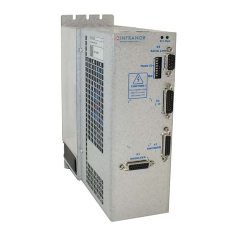
Infranor SMT-BD1 Series User manual

RGB ELEKTRONIKA AGACIAK CIACIEK
SPÓŁKA JAWNA
Jana Dlugosza 2-6 Street
51-162 Wrocław
Poland
biuro@rgbelektronika.pl
+48 71 325 15 05
www.rgbautomatyka.pl
www.rgbelektronika.pl
DATASHEET
www.rgbautomatyka.pl
www.rgbelektronika.pl
OTHER SYMBOLS:
SMT-BD1/1A 220-12-W-T-BS
INFRANOR

YOUR
PARTNER IN
MAINTENANCE
At our premises in Wrocław, we have a fully equipped servicing facility. Here we perform all the repair
works and test each later sold unit. Our trained employees, equipped with a wide variety of tools and
having several testing stands at their disposal, are a guarantee of the highest quality service.
OUR SERVICES
ENCODERS
SERVO
DRIVERS
LINEAR
ENCODERS
SERVO AMPLIFIERS
CNC
MACHINES
MOTORS
POWER
SUPPLIERS
OPERATOR
PANELS
CNC
CONTROLS
INDUSTRIAL
COMPUTERS
PLC
SYSTEMS
Repair this product with RGB ELEKTRONIKA ORDER A DIAGNOSIS ∠
Buy this product at RGB AUTOMATYKA BUY ∠

OPERATING MANUAL
SERIES SMTBD1
DIGITAL BRUSHLESS SERVO CONTROLLERS
(Version 3.1)
European version 3.1
..
..
..
This is a general manual describing a series of servo amplifiers having the capability for driving AC
Brushless servo motors. It concerns only the basic amplifier version SMT-BD1. The options and
other amplifier versions are described in the complementary manuals. This manual may be used in
conjunction with appropriate and referenced drawings pertaining to the various specific models.
Maintenance procedures should be attempted only by highly skilled technicians (EN 60204.1
standard) using proper test equipment. Read your warranty provision carefully before attempting to
adjust or service the unit.

2
RECEIVING AND HANDLING
Upon delivery of the equipment, inspect the shipping containers and contents for indications of
damages incurred in transit. If any of the items specified in the bill of lading are damaged, or the
quantity is incorrect, do not accept them until the freight or express agent makes an appropriate
notation on your freight bill or express receipt.
Claims for loss or damage in shipment must not be deducted from your invoice, nor should
payment be withheld pending adjustment of any such claims.
Store the equipment in a clean, dry area. It is advisable to leave the equipment in its shipping
container until ready for use. Each amplifier is checked carefully before shipment. However,
upon receipt, the user should make sure that the amplifier received corresponds to or is properly
rated in terms of rated voltage and current for the type of motor which is to be driven. The
descriptive label affixed to the amplifier specifies electrical ratings.
Infranor Inc. reserves the right to change any information contained in this manual without notice.
Infranor Inc. does not assume any responsibilities for any errors that may appear nor for any physical or
material damage due to improper handling.
1999 INFRANOR INC.

3
OPERATING MANUAL
INFRANOR
SERIES SMTBD1
“STANDARD”
(March 1999)
1.0.0 GENERAL ............................................................................................................................................ 5
1.1.0 Introduction ....................................................................................................................................... 5
1.2.0 General description............................................................................................................................. 5
2.0.0 SPECIFICATIONS................................................................................................................................ 7
2.1.0 Technical specifications...................................................................................................................... 7
2.1.1 Standard compatibility.......................................................................................................................10
2.1.2 "CE" Marking ...................................................................................................................................10
2.2.0 Block diagram...................................................................................................................................11
2.3.0 Main protections ...............................................................................................................................12
3.0.0 INPUTS / OUTPUTS...........................................................................................................................13
3.1.0 Connector locations...........................................................................................................................13
3.2.0 X1 resolver connector (Sub-D 9 points female) .................................................................................14
3.3.0 X2 position connector (Sub-D 25 points female) ..............................................................................14
3.4.0 X3 test connector..............................................................................................................................14
3.5.0 X4 input - output command connector (Sub-D 25 points male).........................................................15
3.6.0 X5 serial link (Sub-D 9 points male).................................................................................................16
4.0.0 CONNECTIONS..................................................................................................................................17
4.1.0 Connection diagrams.........................................................................................................................17
4.2.0 Wiring recommendation (according to IEC 801 and EN 55011 standards)........................................19
4.2.2 Motor and resolver cables..................................................................................................................19
5.0.0 ADJUSTABLE FUNCTIONS...............................................................................................................20
5.1.0 PC Graphical window (Infranor Digital Drive)...................................................................................20
5.2.0 Parameter file menu (Files)................................................................................................................23
5.3.0 Software configuration menu (Setup) ................................................................................................23
5.4.0 Advanced functions menu..................................................................................................................23
5.5.0 Utilities menu....................................................................................................................................25
5.6.0 Help Menu........................................................................................................................................25
6.0.0 COMMISSIONING..............................................................................................................................26
6.1.0 Checking the amplifier configuration..................................................................................................26
6.2.0 Putting into operation........................................................................................................................26
6.3.0 Amplifier commissioning and adjustment...........................................................................................27

4
7.0.0 FAULT FINDING................................................................................................................................31
7.1.0 System default...................................................................................................................................31
7.2.0 Stored defaults..................................................................................................................................31
7.3.0 Operating problems...........................................................................................................................33
7.4.0 Service and maintenance....................................................................................................................34
8.0.0 APPENDIX..........................................................................................................................................35
8.1.0 Hardware adjustments.......................................................................................................................35
8.2.0 Resolver connections.........................................................................................................................37
8.3.0 Motor connections ............................................................................................................................37
8.4.0 Logic control adjustment...................................................................................................................40
8.5.0 BPCW software installation...............................................................................................................42
8.6.0 360oshield on the connectors............................................................................................................44

5
1.0.0 GENERAL
1.1.0 Introduction
Series SMT-BD digital servo modules are PWM servo amplifiers that provide speed control for AC sinusoidal
motors (brushless) with transmitter resolver.
The pluggable SMT-BD1 system is available as a single-axis block version or as a multi-axis version that can
receive up to seven axes in a standard 19" rack including the power supply.
The basic amplifier module SMT-BD1 / Aor Bprovides speed control for AC synchronous motors.
•SMT- BD1 / C version with option card SMT - Ix allows the direct position control of the motor by means of
an incremental position input command (stepping motor emulation).
•SMT- BD1 / D version with option card SMT - Ix allows the direct position control of the motor by means of
an incremental encoder position input command for applications such as electronic gearing.
•SMT- BD1 / E version with option card SMT - Ix allows the tension control of a material (thread or film) by
means of an analog tension sensor for winding/unwinding applications master/slave drives.
•SMT- BD1 / F version with option card SMT - Ix allows the indexing of a spindle motor axis for tool changes,
according to four programmable positions over one revolution.
•SMT- BD1 / G version with option card SMT - Ix allows product registration function using master/slave
operation.
•SMT- BD1 / H version with option card SMT - Ix allows all communication with the CAN interface instead of
the +10V.
The parameter setting software BPCW, which is IBM-PC compatible with the WINDOWS®operating system,
allows the display of all amplifier parameters as well as their easy modifications.
1.2.0 General description
SMT-BD1 amplifiers have their own DC/DC converter to provide appropriate logic voltage. This power supply
provide the bus power voltage of 310 VDC as well as the auxiliary power supply which is necessary particularly
when the position output information needs to be saved.
Each module is packaged as a 6 U "double Eurocard":
•one power board with IGBT transistors
•one logic board with DSP (Digital Signal Processing).
SMT- BD1 amplifier controls directly the motor torque and speed by means of the information provided by a
transmitter resolver sensor.
The motor speed or torque input command is an analog command (± 10 V). The motor position is available as two
channels (A and B) and their complements, and one or several marker pulse(s) per revolution.
The number of pulses per revolution is programmable. Errors are displayed on the amplifier front panel.
All control parameters are programmable by means of a serial link and saved in a single EEPROM memory. The
auto-configuration and auto-tuning functions allows for easy and quick commissioning of the amplifier.

6
The basic software BPCW, which is IBM-PC compatible with the WINDOWS®operating system, allows the
display and modification of all amplifier parameters. The extended version of the BPCW software include the
digital oscilloscope, the simulation function as well as the cogging torque compensation.

7
2.0.0 SPECIFICATIONS
2.1.0 Technical specifications
Operating voltage DC bus 310 VDC (270 V < DC bus < 340 VDC)
Auxiliary supply voltage 310 VDC ( 200 V < Uaux < 340 VDC)
Motor phase-phase output voltage 200 Vrms for DC bus 310 V
Output currents for the Fusing mode of the I2t protection (see chapter 8.3.3)
AMPLIFIER U rated Imax (A rms) Amplifier max. rated current (Arms)
(Vrms) 1 s WITHOUT
FAN* FAN TYPE
1* FAN TYPE
2*
SMT-BD1 - 220/04 240 4,4 2
SMT-BD1 - 220/08 240 8,8 4
SMT-BD1 - 220/12 240 13,8 6
SMT-BD1 - 220/17 240 17,7 8,5
SMT-BD1 - 220/30 240 30,8 10 12 15
SMT-BD1 - 220/30r 240 30,8 10 15
SMT-BD1 - 220/45 240 48,6 10 15 20
SMT-BD1 - 220/45r 240 48,6 10 20 23
SMT-BD1 - 220/60 240 61 10 19 25
SMT-BD1 - 220/60r 240 61 12 26 30
SMT-BD1 - 220/70 240 70 25 30 35
SMT-BD1 - 220/100 240 100 25 30 35
Output currents for the Limiting mode of the I2t protection (see chapter 8.3.3)
AMPLIFIER U rated Imax (Arms) Amplifier continuous current (Arms)
(Vrms) 1 s WITHOUT
FAN* FAN TYPE
1* FAN TYPE
2*
SMT-BD1 - 220/04 240 4,4 2
SMT-BD1 - 220/08 240 8,8 4
SMT-BD1 - 220/12 240 13,8 6
SMT-BD1 - 220/17 240 17,7 8,5 8,5
SMT-BD1 - 220/30 240 30,8 8,5 12 15
SMT-BD1 - 220/30r 240 30,8 10 15
SMT-BD1 - 220/45 240 48,6 8,5 15 18
SMT-BD1 - 220/45r 240 48,6 10 20 23
SMT-BD1 - 220/60 240 61 8,5 17 20
SMT-BD1 - 220/60r 240 61 12 26 30
SMT-BD1 - 220/70 240 70 17 30 35
SMT-BD1 - 220/100 240 100 25 30 35
* Maximum ambient temperature = + 40° C, fan 1 = 56 l/s, fan 2 = 90 l/s.
Note: SMT-BD1-X/Xramplifiers are equipped with an additional heatsink in order to increase the rated current.
The width of these amplifiers is then 18 TE instead of 12 TE.

8
PWM Switching frequency 10 KHz
Minimum inductance between phases 1 mH
Current regulator (PI) adjusted to motor
Current loop bandwidth Cut-off frequency for 45° phase shift: > 1 KHz
Internal current limitation Imax: 20% to 100 % Irated: 20% to
100 % of Imax Imax duration = 1 second
External current limitation 0 to 10 V (resolution = 12 bits)
100 to 0 % of the internal Imax limitation
Analog speed input command ±10 V, standard resolution = 12 bits and
16 bits in option
Motor accel/decel ramp range From 0 to 30 s between zero speed and
max. speed
Speed regulator PI2Sampling period = 0,5 ms
Integrator anti-saturation system
Antiresonance filter
Adjustable numerical gains
Speed loop bandwidth Cut-off frequency for 45° phase shift
Programmable : 50 Hz, 75 Hz or 100 Hz
Max. motor speed Adjustable from 100 rpm to 14000 rpm
Speed range 2048 : 1 with 12 bits input command
32768 : 1 with 16 bits input command
Encoder position output * Quadrature output A and B channels with n marker
pulse(s) per revolution. Programmable
resolution: max. 8192 ppr up to 900 rpm
max. 4096 ppr up to 3600 rpm
max. 1024 ppr up to 14000 rpm
Accuracy: 8 arc minutes + ¼ point
(2 arc minutes + ¼ point on special request)
Analog outputs (test points) Speed input command (CV): ±10 V for ± max. speed
Speed monitor (GT) ±8 V for ±14000 rpm
Current input command (IDC): ±10V, DAC OUT 1
8 bits resolution.
Current monitor (Imon.): ± 10 V, DAC OUT 2: 8 bits
resolution
Logic inputs Enable / Disable: ENABLE
Limit switch +: FC+
Limit switch - : FC-
Current command: CI
Zero speed input command: CV0
Reset: RAZ

9
* The total position accuracy must take into account the accuracy of the resolver used

10
Logic outputs Relay contact Umax = 50 V,
Imax = 100 mA, Pmax = 10 W
• "Amp ready": closed if amplifier OK, open if default
• "Power ready": closed if power OK, open if default
• IDYN signal: open if I2t threshold is reached
Error display LED on front panel and diagnostic by serial link
Motor and application parameter setting Serial link RS232 (standard) or RS422 / 485 (option)
Automatic functions Amplifier adjustment to the motor
(AUTOPHASING)
Automatic regulator tuning (AUTOTUNING)
Offset compensation on analog input CV
Electromagnetic compatibility IEC standards 801- 2 - 3 - 4, level 4
Conducted and radiated disturbances EN 5011 Group 1, class A
Electrical standards for industrial machines N 60204.1: 1500 VAC - 1min insulation
Current leakage >3mA (EMI filters)
Temperature storage - 20° C to + 70° C
operation 5° C to +40° C
From 40°C on, the rated currents must be reduced
of 3 %/°C.
Max. temperature: 50°C
altitude: 1000 m (3300 feet)
moisture: < 50 % at 40°C and < 90 % at 20°C
(EN 60204.1 standard)
Cooling Natural convection or forced air, according to the
rated current (see current table)
2.1.1 Standard compatibility
SMT-BD1 amplifiers operating either in the RBF rack equipped with the mains filter BF-35/70, or the SMTBM-
20A single axis and BF-35, have been approved for their conformity with the Electromagnetic Compatibility
standards:
•EN 55011, Group 1, Class A (conducted and radiated radioelectric disturbances)
•IEC 801 - 2 - 3 - 4 (noise immunity).
Results and test conditions of the LCIE (Laboratories Central des Industries Electriques), which is approved by the
European Community, are referenced with n° 416040, 416041, 416042, and 416043.
Results of the tests made according to the Low Voltage directive is referenced in the LCIE report n° 413777.
Standard to be applied to the electrical equipment’s of industrial machines: EN 60204.1.
2.1.2 "CE"Marking
CE recognition marking has been affixed since 1995.

11
2.2.0 Block diagram

12
2.3.0 Main protections
2.3.1 Stored protections
PROTECTION ERROR DISPLAY LED*
Amplifier rated current overload #:I2t
•flashing display = Idyn signal (I2t threshold is reached)
•continuous display = amplifier inhibited (I2t default)
Resolver cable interruption Resolver
Power stage failure: Power stage
•power supply overvoltage
•internal switch protection
•short-circuit between phases
Resolver converter failure R. D. C
Amplifier overtemperature °C Amp
Power supply undervoltage Undervolt.
Motor overtemperature °C Motor
Default of the amplifier parameter storage EEPROM
Amplifier automatic procedure: Busy
•flashing display = procedure operating
•continuous display = operating error
#The operation mode of the I2t protection is described in chapter 8.3.3.
* = LED is unlit; = LED is lit.
Reset of a stored default can be made:
•by means of the RESET function in the BPCW software
•via the default RESET input (pin 13 of the X4 connector)
•by switching off the amplifier power supply.
2.3.2 Fuse protections
F1 : Control of average DC current of the power board supply.
F2 : Control of average DC current of the logic board supply.
AMPLIFIER TYPE F1 F2
Power Logic
SMTBD1-220/04 to 12 10 AT 1 A
SMTBD1-220/17 to 30 15 AT 1 A
SMTBD1-220/45 20 AT 1 A
SMTBD1-220/60
SMTBD1-220/70 20 AT
40 AT 1 A
5 AT
SMTBD1-220/100 40 AT 5 AT

13
3.0.0 INPUTS / OUTPUTS
3.1.0 Connector locations
3.1.1 Front connectors SMTBM-20A single axis block
For more detailed information regarding the power connection, please see the SMTBM-20A manual
3.1.2 RBF rack connectors
For more detailed information regarding the power connection, please see BF Rack manual

14
3.2.0 X1 resolver connector (Sub-D 9 points female)
PIN FUNCTION REMARKS
1TC (pin H sensor connector) If thermal switch connected to X1
6Shield connection If no "360°" connection on the connector
2TC (pin I sensor connector) If thermal switch connected to X1
7S1 (pin C sensor connector) MAVILOR motor with resolver
3S3 (pin D sensor connector) MAVILOR motor with resolver
8S4 (pin B sensor connector) MAVILOR motor with resolver
4S2 (pin A sensor connector) MAVILOR motor with resolver
9R2 (pin F sensor connector) MAVILOR motor with resolver
5R1 (pin E sensor connector) MAVILOR motor with resolver
For resolver connections other than the MAVILOR motors, see resolver wiring table in chapter 8.2.0.
3.3.0 X2 position connector (Sub-D 25 points female)
PIN FUNCTION I / O REMARKS
1Marker Z/ ODifferential output of the encoder marker pulse (5 V, 20 mA max.)
2Marker Z ODifferential output of the encoder marker pulse
3Channel A/ ODifferential output of the encoder channel A/ (5 V, 20 mA max.)
4Channel A ODifferential output of the encoder channel A
5Channel B/ ODifferential output of the encoder channel B/ (5 V, 20 mA max.)
6Channel B ODifferential output of the encoder channel B
70 V O
8 and 9 reserved A
10 and 11 0 V O
12,13,14 reserved B
15,16,17 reserved
18 and 19 0 V OZ
20,21,22 reserved
23,24 reserved
25 0 V O
3.4.0 X3 test connector
PIN FUNCTION REMARKS
1 - 6 0 Volt
2Current input command I DC ± 10 V; resolution: 8 bits, linearity 2% (DAC out 1)*
3Speed input command CV ± 10 V for ± max. speed
4Speed monitor GT ± 8 V for ± 14000 rpm
5Current monitor I mes ± 10 V; resolution: 8 bits, linearity 2% (DAC out 2)*
* See “BPCW Options” manual, section “Digital Oscilloscope”
Linearity = 10 % for logic board type 01612A, 01612B or 01612C.

15
3.5.0 X4 input - output command connector (Sub-D 25 points male)
Pin Function I / O REMARKS
1Limit switch + IPositive or negative logic (see chapter 8.4.1)
14 Limit switch - IPositive or negative logic (see chapter 8.4.1)
24 0 Volt of limit switch I
20 ENABLE IPositive or negative logic (see chapter 8.4.1)
23 0 Volt ENABLE I
4Current command CI IPositive or negative logic (see chapter 8.4.1)
7CV0 Zero speed input command IPositive or negative logic (see chapter 8.4.1)
25 0 Volt I
13 RESET IAmplifier reset (contact between 13 and 12)
12 0 Volt of RESET input I
17 Input command CV + I± 10 V speed input command for max. speed
16 Input command CV - Ior current ± 10 V input command for Imax with "CI"
input active
15 0 Volt speed input command CV I
3Current limitation I limit IExternal current limitation
0 to 10 V for 100 % to 0 % of Imax
10 Speed monitor output O± 8 V for ± 14000 rpm; linearity: 10% max. load: 10 mA
2Current monitor output O± 10 V; resolution: 8 bits; load: 10 mA; (DAC out 2)
11 0 Volt analog output O10 V for amplifier current size.
8, 9 I dyn signal ORelay contact: open if I dyn threshold is reached
Pmax = 10 W with Umax = 50 V or Imax = 100 mA
18, 19 Amplifier ready ORelay contact: closed if amplifier OK, open if fault.
Pmax = 10 W with Umax = 50 V or Imax = 100 mA
21 + 15 V O50 mA maximum output current
22 - 15 V O50 mA maximum output current
5, 6 not connected
For the use of “negative” command logic, see chapter 8.4.1.

16
3.5.1 Analog input specification
+
-
10K
10K
10K
10K
20K
20K
22 nF
10 nF 10 nF
X4/16
X4/17 CV+
CV-
+
-
10K 10K
20K
22 nF
10 nF
X4/15
X4/3 ILIM
Gnd
3.5.2 Logic inputs / outputs specification
47K
+5V
4,7K
47 nF
X4/7 CV0
X4/25 0V
4.7V
Log+ Log-
+15V
X4/18 AOK
X4/19 AOK/
same for FC+, FC-, CI, ENABLE
same for I DYN, Power OK
3.6.0 X5 serial link (Sub-D 9 points male)
PIN FUNCTION REMARKS
50 Volt GND (connection of the shield if no "360°" connection on the connector)
2TXD Transmit data RS 232
3RXD Receive data RS 232
6TXH Transmit data RS422/485
7TXL Transmit data RS422/485
8RXL Receive data RS422/485
9RXH Receive data RS422/485

17
4.0.0 CONNECTIONS
4.1.0 Connection diagrams
4.1.1 Power connection with the RBF rack or the SMTBM-20A single axis module
K
K.1
L1
L2
L3
N
380
220
F
Power
relay Aux.
relay
U
V
W
GND
X1
AMPLIFIER
ENABLE
relay
AMP. READY
*POWER
READY
MOTOR
RES
4 cables + shield
6 pair shielded cables
(+ thermal probe)
!Rack chassis grounding
(*): Only for BF rack
BF 35 70 90
F20 40 60
AUTO-TRANSFORMER
3AT
curve C
L1 L2 L3
Filter
BF 35/70
Aux
GND
!* POWER OK: Only available on X5 of the rack back
plane.
If not using the POWER OK signal, make the jumper
JK on the amplifier in order to have the AMP. READY
signal taking into account the power statement.
Aux.
“ON”
Aux.
“OFF”
K.1
ENABLE
Power
“ON”
Power
“OFF”
Aux. relay
Power relay
Disable
* POWER OK
ENABLE relay
24 V
0 V
Amp.
ready
Aux. relay Power
relay
Aux.
relay
Power relay
For more details about the power connection, see SMTBM 20 A single axis rack or RBF rack manual.

18
4.1.2 Logic connection
Other manuals for SMT-BD1 Series
1
This manual suits for next models
21
Table of contents
Other Infranor Controllers manuals
