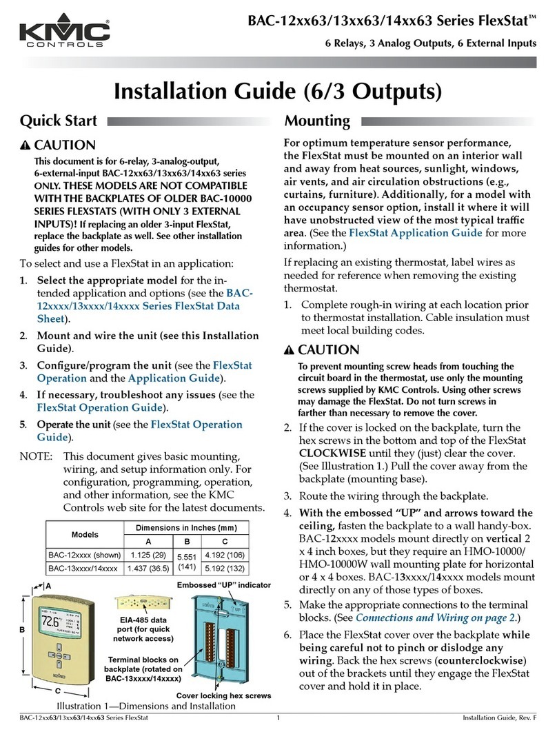
KMC Controls BAC-5900 Series User manual
Other KMC Controls Controllers manuals
KMC Controls
KMC Controls MEP-4201 User manual
KMC Controls
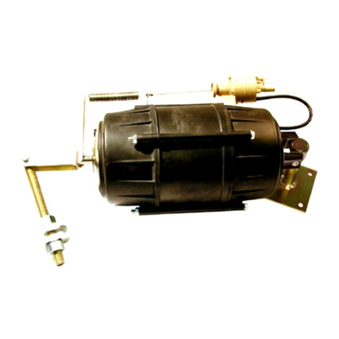
KMC Controls MCP-1160 Series User manual
KMC Controls
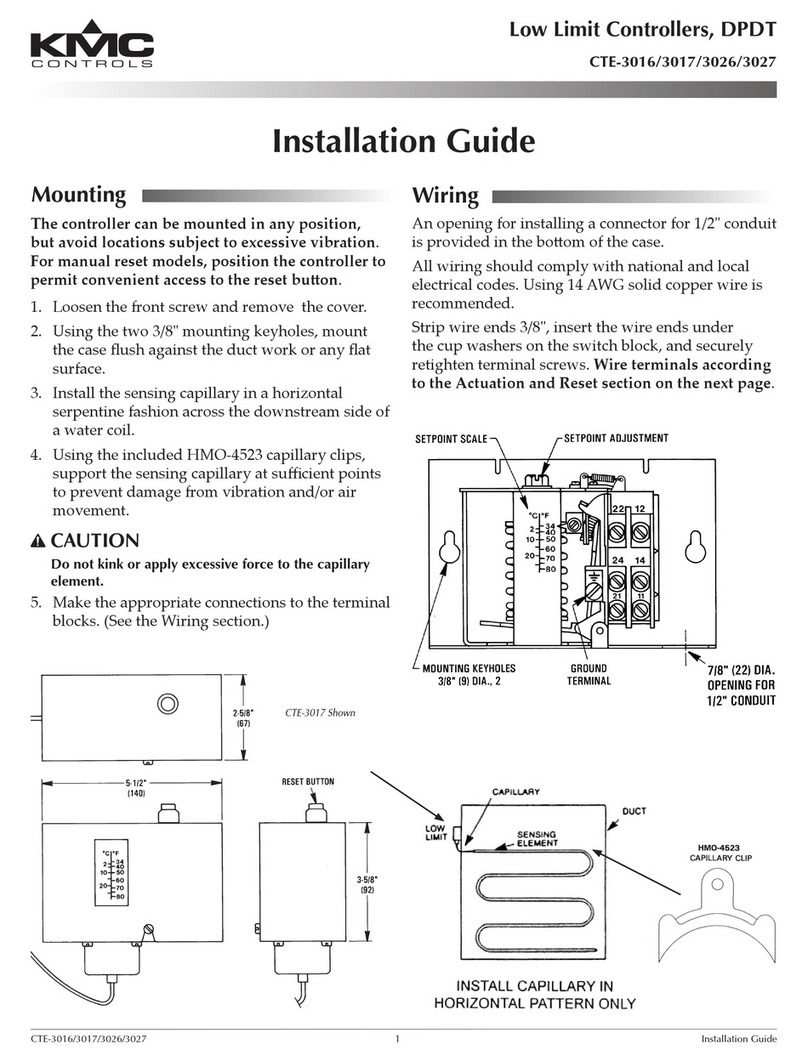
KMC Controls CTE-3017 User manual
KMC Controls
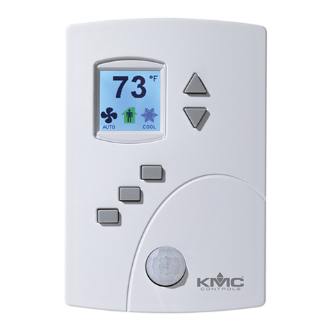
KMC Controls BAC-4000 series User guide
KMC Controls
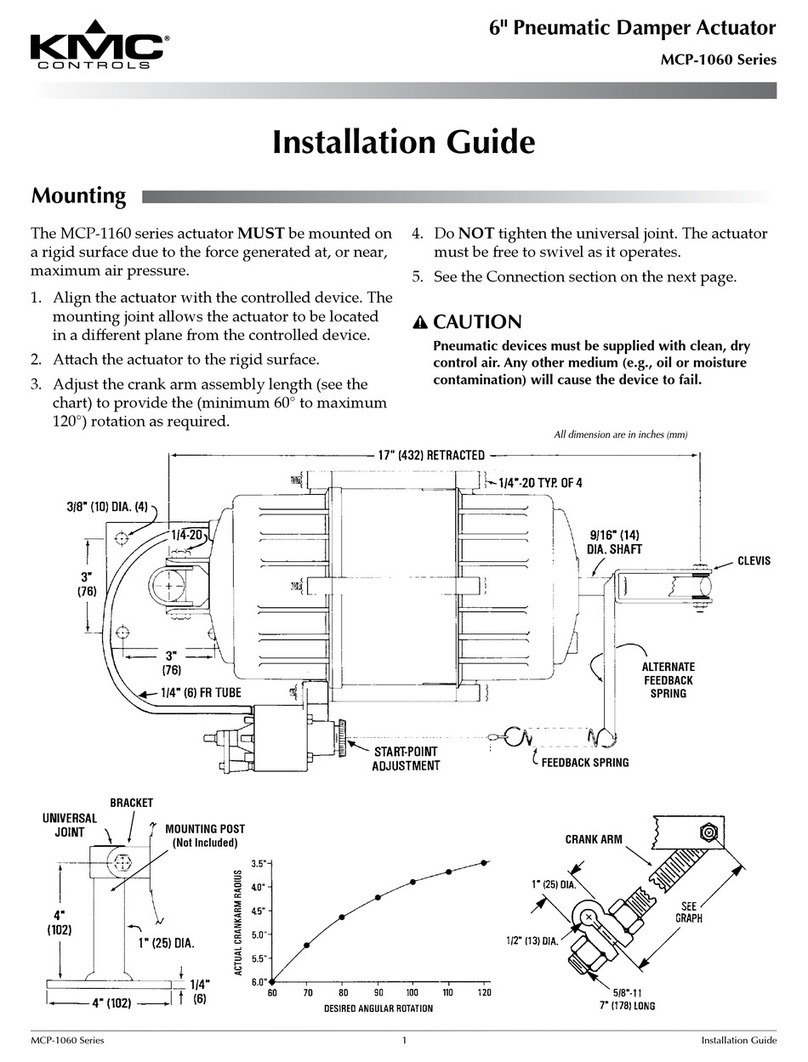
KMC Controls MCP-1060 Series User manual
KMC Controls
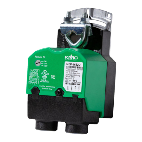
KMC Controls MEP-46 Q Series User manual
KMC Controls
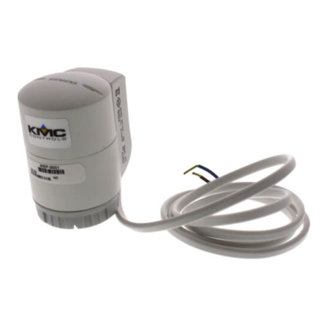
KMC Controls MEP-3001 Operating instructions
KMC Controls
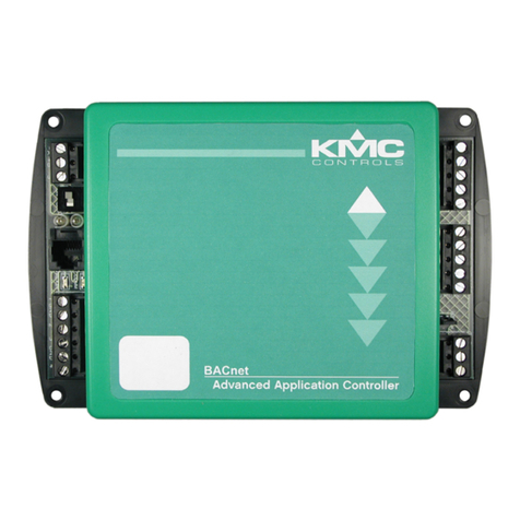
KMC Controls BAC-7302 Operating instructions
KMC Controls
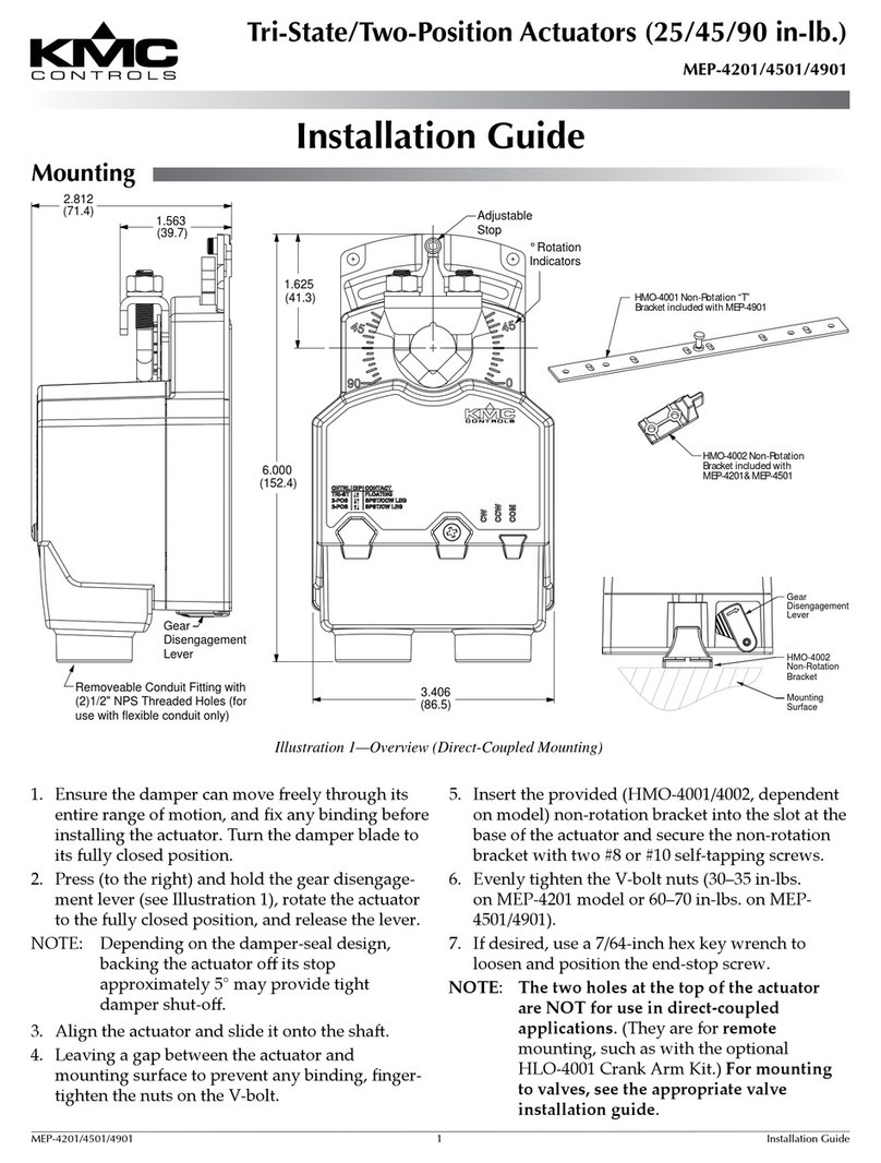
KMC Controls MEP-4201 User manual
KMC Controls
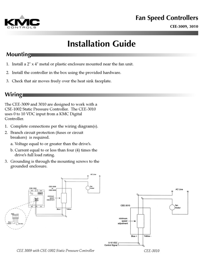
KMC Controls CEE-3009 User manual
KMC Controls
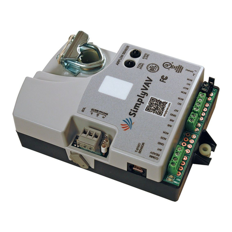
KMC Controls SimplyVAV BAC-8205 User manual
KMC Controls
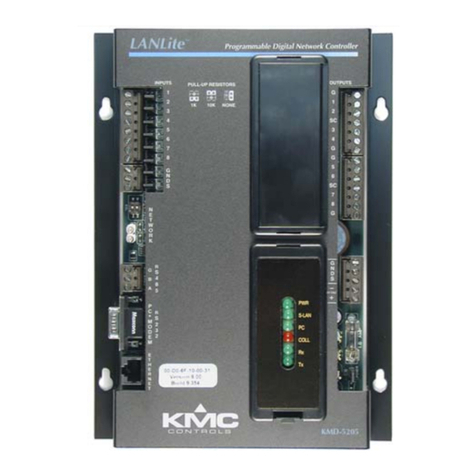
KMC Controls KMD-5205 Operating instructions
KMC Controls
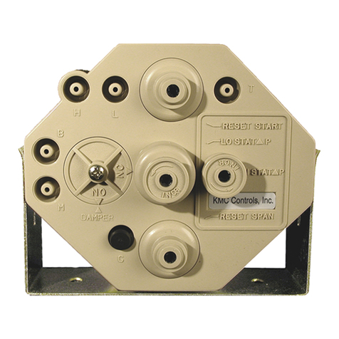
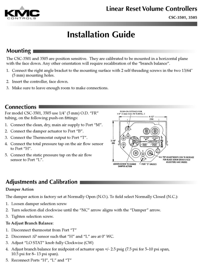
KMC Controls CSC 3000 Series User guide
KMC Controls
KMC Controls CSC-3501 User manual
KMC Controls
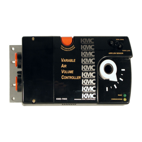
KMC Controls KMD-7001 Original operating instructions
KMC Controls
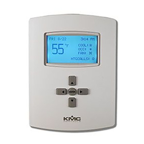
KMC Controls FlexStat BAC-120063CW-ZEC Operator's manual
KMC Controls
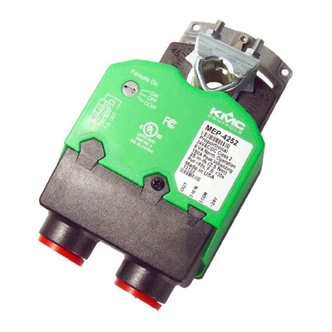
KMC Controls MEP-4 Series User guide
KMC Controls
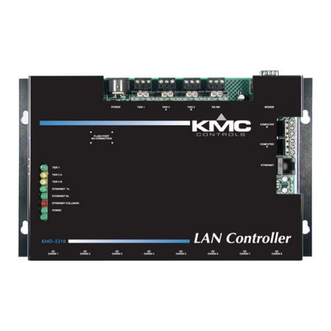
KMC Controls KMD-5210 Operating instructions
KMC Controls
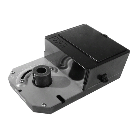
KMC Controls MEP-5062 User manual
KMC Controls
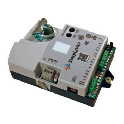
KMC Controls SimplyVAV BAC-8001 User guide
Popular Controllers manuals by other brands

Digiplex
Digiplex DGP-848 Programming guide

YASKAWA
YASKAWA SGM series user manual

Sinope
Sinope Calypso RM3500ZB installation guide

Isimet
Isimet DLA Series Style 2 Installation, Operations, Start-up and Maintenance Instructions

LSIS
LSIS sv-ip5a user manual

Airflow
Airflow Uno hab Installation and operating instructions
