VERDER CARBOLITE GERO EPC3000 Series Manual

Installation, Operation and Maintenance Instructions
Controller Manual
3016 Controller
3016 Controller
MEN-3016_CTRL (19-08-2020)

Contents
This manual is for guidance on the use of the Carbolite Gero product specified on the
front cover. This manual should be read thoroughly before unpacking and using the
furnace or oven. The model details and serial number are shown on the back of this
manual. Use the product for the purpose for which it is intended.
1.0 Introduction 4
1.1 Features 4
1.2 Technical Terms 5
2.0 Navigation 6
3.0 Start Up 7
4.0 Operator Levels 8
4.1 Changing Operator Level 8
4.1.1 Operator Level 2 8
4.1.2 Operator Level 3 9
4.1.3 Configuration Level 9
4.1.4 Logging Out of Operator Level 3 and Configuration Level 10
5.0 Simple Temperature Control 11
5.1 Sensorbreak 11
6.0 Programming 12
6.1 Run / Hold / Reset a Program 12
6.1.1 Run 12
6.1.1.1 Shortcut: Run Program 12
6.1.2 Hold 12
6.1.2.1 Shortcut: Hold Program 13
6.1.3 Reset 13
6.1.3.1 Shortcut: Reset Program 14
6.2 Programmer List 14
6.3 Create / Edit a Program 16
6.4 Event Outputs - Customer Notes 20
6.5 Program Example 21
7.0 Alarm Relays (optional) 23
7.0.1 Alarm State 23
7.0.2 Hysteresis 24
7.1 Alarm Outputs - Customer Notes 25
8.0 Controller Settings 26
2

9.0 Controller Configuration 29
9.0.1 Menu Lists 30
10.0 Offset Calibration 41
10.1 Single-Point Calibration 41
11.0 Using Autotune to Optimise Temperature Control 43
12.0 Communications Connections 45
12.1 Configuring iTools Communications Settings 45
12.1.1 Ethernet Connections 46
12.1.2 RS485 Connections (optional) 48
12.2 Establishing a Connection (Windows 10) 49
13.0 Navigation Diagrams 51
13.1 Operator Level 1 51
13.2 Operator Level 2 51
13.3 Operator Level 3 52
13.4 Configuration Level 53
13.5 Controller Replacement 53
3

1.0 Introduction
The 3016 programmable temperature controller is part of the EPC3000 range of
temperature controllers.
It uses PID (Proportional Integral Derivative) algorithms to adjust the heating power
and control the temperature within the product.
Users navigate through the controller by pressing the four buttons positioned below the
display.
1.1 Features
The 3016 features:
l1 program slot with up to 24 configurable segments
lRamp, Dwell, Step, Call and End segment types
l2 relay outputs that can be pre-configured as event outputs, or alarms (must be spe-
cified when ordered)
lEthernet connection
lCybersecurity communications robustness certification
4

1.2 Technical Terms
Due to the complex nature of temperature control, this manual uses technical terms.
Here is a list of some of the terms used within this manual, alongside their explanation:
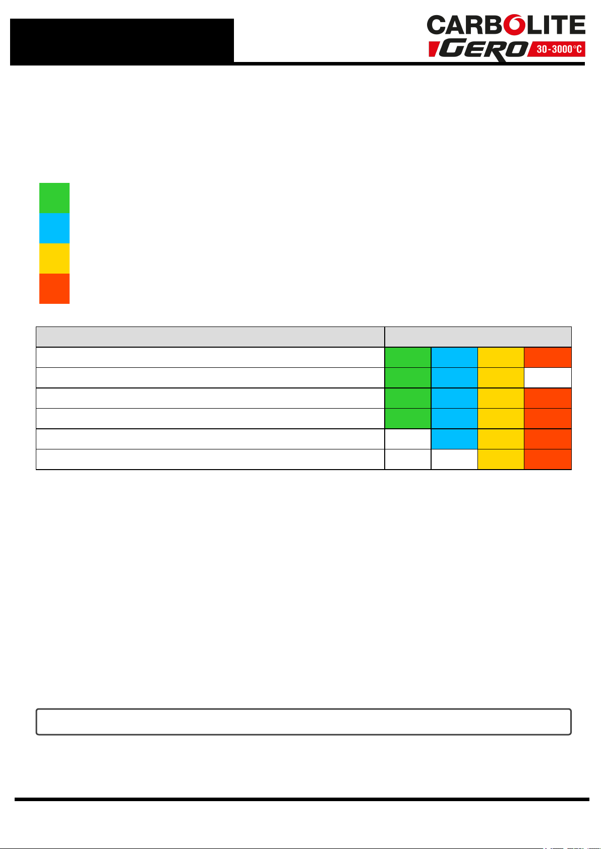
Term Description
Setpoint The target temperature the furnace or oven is trying to reach (°C)
Over-
Temperature
Protection
A system to prevent the product or process being damaged if the
temperature has increased above a temperature specified by the user
(over-temperature setpoint). Power to the heating elements is stopped
until either the temperature of the product drops below the over-
temperature setpoint, or the user manually increases the over-
temperature setpoint
Over-
Temperature
Setpoint
The temperature at which the over-temperature protection system
triggers
Heating
element
The electrically powered heating device used within the product
(furnace or oven)
Thermocouple A thermoelectric device for measuring temperature
PID Proportional Integral Derivative - the mathematical control system
used by the controller
Program A series of instructions that tell the controller how to behave. A
program is divided into sections called "segments"
Segment
A section of a program. A program can have 24 individual segments.
There are 6 different segment types that can be configured. The
segments define how the controller behaves when a program reaches
that segment.The last segment of a program must always be an "End"
type
Holdback
Used when running a program. Holdback is the amount (in °C /°F / K)
by which the programmed setpoint can run ahead of the actual
measured temperature before holdback operates and prevents the
program from progressing until the actual temperature catches up.
This can be applied to either heating, cooling or both, depending on the
"Holdback Type" set by the user
Ramp Rate The amount of degrees (°C /°F / K) the temperature should increase
per second, minute or hour (dependant on "Ramp Units")
Ramp Units Used to define whether the temperature should increase at X°C per
second, X°C per minute or X°C per hour
5

2.0 Navigation
Users navigate through the controller by pressing the four buttons positioned below the
display. For some functions, a combination of buttons must be pressed simultaneously.
1 Display
2 Alarm Indicator
3 Segment Indicator
4 Page Button
5 Scroll Button
6 Down Button
7 Up Button
8 Output Indicator
9 Setpoint Temperature
10 Actual Temperature
Note: The output indicator 1 icon will appear to
show that power is being directed to the product
heating elements. Output indicators 2 and 3 are
linked to other outputs within the controller.
6

3.0 Start Up
When powered on, the 3016 controller will cycle through a series of initial test screens.
After 7 seconds, it will default to the home display.
The home display shows an overview of the controller, including details such as the
actual temperature and setpoint.
Functionality permissions are set as Operator Level 1 by default.
Note: If the controller is power-cycled while being used at a higher permission level,
it will return to Operator Level 1 and the user must login again to access higher level
functionality.
7

4.0 Operator Levels
There are 4 operator levels available within the 3016. These user levels control access
to functionality within the controller via permissions.
The default operator level is Level 1.
Level 1
Level 2
Level 3
Config. Level
Functionality Permissions
Login / Change User Level
Access Home Display
Change Setpoint (including Over-Temperature Setpoint)
Run a Pre-configured Program
Edit / Create a Program
Edit Controller Settings
4.1 Changing Operator Level
4.1.1 Operator Level 2
To access Operator Level 2:
1. From the Home display, press and hold the page button for 3 seconds until the
GOTO display appears.
2. Use the up and down arrow buttons to select the operator level you wish to access.
3. Press the scroll button to confirm. The CODE display will appear. You now have to
input a passcode.
4. Use the up and down arrows to change the number input.
5. Press the scroll button to move to the next digit.
6. When you have finished inputting the passcode, wait for 2 seconds. If entered cor-
rectly, PASS will appear on the display and you will now have access to additional
functionality.
Note: The passcode to access Operator Level 2 is 0009
8

Changing Operator Level to Level 2
4.1.2 Operator Level 3
To access Operator Level 3:
1. Press and hold the page button until Lev3 GOTO appears.
2. Press the scroll button to confirm. The CODE display will appear. You now have to
input a passcode.
3. Use the up and down arrows to change the number input.
4. Press the scroll button to move to the next digit.
5. When you have finished inputting the passcode, wait for 2 seconds. If entered cor-
rectly, PASS will appear on the display and you will now have access to additional
functionality.
Note: The passcode to access Operator Level 3 is 0005
4.1.3 Configuration Level
To access Configuration Level (Config):
1. Press and hold the page button until Lev3 GOTO appears.
2. Press the up button until CONF appears.
3. Press the scroll button to confirm. The CODE display will appear. You now have to
input a passcode.
4. Use the up and down arrows to change the number input.
9

5. Press the scroll button to move to the next digit.
6. When you have finished inputting the passcode, wait for 2 seconds. If entered cor-
rectly, PASS will appear on the display and you will now have access to additional
functionality.
Note: The passcode to access Configuration Level is 0095
4.1.4 Logging Out of Operator Level 3 and Configuration Level
To log out of operator levels with higher permissions:
1. Press and hold the page button until the GOTO display appears.
2. Use the up and down buttons to select the next user level you want to log into.
Note: If logging out of Configuration Level, the user can only log out to Operator
Level 1. The controller will go through a short test cycle to accept any new
configuration applied.
Note: Passcodes are not required if changing from a higher operator level to a lower
operator level, e.g. from Operator Level 2 to Operator Level 1.
10

5.0 Simple Temperature Control
The 3016 can be used as a programmer or as a simple temperature controller.
The controller has been configured so that it cannot heat above the maximum stated
temperature for the product you have purchased.
To set a setpoint temperature:
1. Press the Up and Down buttons to increase or decrease the setpoint value. Holding
a button down will adjust the value at a faster rate.
2. Once the buttons are released the 3016 will begin to control the temperature
according to the new setpoint.
Changing the Setpoint
Note: The output indicator 1 icon will appear to show that power is being directed to
the product heating elements.
5.1 Sensorbreak
If a thermocouple becomes disconnected or fails, the controller display will flash
between the error messages S.brk and bAd, indicating that the thermocouple is unable
to read a temperature.
The controller will automatically switch to display a "high point" value i.e. the maximum
temperature the product is configured to achieve, and further heating will be
prevented.
Note: If any alarm relay outputs are configured, then the icons for these will also
appear on-screen
11

6.0 Programming
The 3016 is supplied with one program slot containing 24 configurable segments.
All users can run a pre-existing program, however to create or edit a program the user
must be logged in to Operator Level 2 (see section 4.0).
6.1 Run / Hold / Reset a Program
6.1.1 Run
To run an existing program:
1. From the home display, press the page button to access the PROGLIST (Program
List) display.
2. Press the scroll button until you reach the P.MODE (Program Mode) parameter.
3. Press the up and down buttons to change the program mode from rESET to RUN.
The program will start to run.
6.1.1.1 Shortcut: Run Program
lPress the up and down buttons
together. The program will start to
run.
lIf scrolling text is configured,
<PROGRAMRUNNING> will appear on the
display.
lThe segment indicator will appear to
show whether the program setpoint is
ramping up, dwelling, or ramping
down.
6.1.2 Hold
To hold a program that is currently running:
1. From the home display, press the page button to access the PROGLIST (Program
List) display.
2. Press the scroll button until you reach the P.MODE (Program Mode) parameter.
3. Press the up and down buttons to change the program mode from RUN to HOLd.
The program will hold until the operator either resumes or resets the program.
12

6.1.2.1 Shortcut: Hold Program
lPress the up and down buttons
together while the program is run-
ning. The program will hold until the
up and down buttons are pressed
again.
lIf scrolling text is configured,
<PROGRAMHOLD> will appear on the
display.
6.1.3 Reset
To reset a program that is currently running:
1. From the home display, press the page button to access the PROGLIST (Program
List) display.
2. Press the scroll button until you reach the P.MODE (Program Mode) parameter.
3. Press the up and down buttons to change the program mode from RUN to rESET.
The program will reset and stop running.
13

6.1.3.1 Shortcut: Reset Program
lPress and hold the up and down but-
tons for 3 seconds to reset the pro-
gram.
lThe program will stop running and
return to the home display.
Note: When a program is running a "Programmer List" becomes available within the
controller. (see section 6.2.)
6.2 Programmer List
When a program is running, additional parameters become available in the
Programmer List menu.
To access the programmer list when a program is running:
1. From the home display press the page button display "Prog List".
2. Press the scroll button to cycle through the available parameters.
PROG List (Program running)
Display Parameter Description/ Use
P.NUM Program
Number Displays the program number. This parameter is read only.
14

P.NAME Program
Name
Displays the name of the program. This parameter is read
only.
P.CUR
Current
Program
Number
Displays the number of the program currently running. This
parameter is read only.
C.NAME
Current
Program
Name
Displays the name of the program currently running. This
parameter is read only.
P.MODE Program
Mode
Displays the status of the current program. Can be
adjusted using the up and down buttons:
lRUN - The program is running.
lHOLd - The program is paused.
lReset - The program is stopped.
P.SP Program
Setpoint
Displays the setpoint of the current program. This
parameter is read only.
P.TIM.L Program
Time Left
Displays the amount of time left until the program
completes. This parameter is read only.
Note: The display will show a maximum time of 500
hours, however some programs may exceed this length
of time. The value displayed does not take into account
the effect of holdback within a program.
P.CYC.L Program
Cycles Left
Displays the amount of program cycles left to run. This
parameter is read only.
S.NUM Segment
Number
Displays the number of the current program segment. This
parameter is read only.
S.NAME Segment
Name
Displays the name of the current program segment.
This parameter is read only.
S.TYPE Segment
Type
Displays the segment type of the current program segment.
This parameter is read only.
S.TIM.L Segment
Time Left
Displays the amount of time left until the current segment
completes. This parameter is read only.
TSP Target
Setpoint
Displays the target setpoint of the current segment. This
parameter is read only.
Note: Only displayed if the current segment type is
RAtE,tImE, or StEP.
R.Rate Ramp Rate
Displays the current ramp rate of the segment.
Note: Only displayed if the current segment type is
RAtE,tImE, or StEP.
EVT.1 /
evt.2 Event 1 / Displays whether any event outputs or alarms are on or off.
15

Event 2 The number displayed is dependent on the amount of
outputs or alarms configured. This parameter is read only.
P.ADVN Program
Advance
Enables the operator to force the program to advance to
the next segment.
lYes
lNo
Note: This parameter can only be edited when logged in
at Operator Level 2.
6.3 Create / Edit a Program
Note: To create a new program, or edit an existing program, the user must first be
logged in at Operator Level 2(see section 4.0).
To access program setup:
1. From the home display, press the page button twice to reach the P.Set option.
2. Press the scroll button to access the list of parameters.
3. Continue to press the scroll button to navigate through the list of parameters.
4. Adjust parameter options using the up and down buttons.
5. When you have finished setting up the program, press the page button multiple
times to return to the top of the menu you are currently in (S.NUM >P.NUM >P.SEt
> Home display). Alternatively, the display will automatically return to the home dis-
play after 30 seconds of inactivity.
Note: The controller will initially scroll through the parameters that apply to the whole
of the program. Continue to press the scroll button to reach parameters specific to a
particular segment within the program.
16

Program Setup
Display Parameter Description/ Use
P.NUM Program
Number
Displays the program number. This parameter is 1by
default.
P.NAME Program
Name
Displays the name of the program. This parameter is P1 by
default.
HB.STY Holdback
Style
Used to define whether the same holdback settings should
apply for the entire program, or whether they can be
defined for each individual segment.
lIf PROG is selected, you will be able to set parameters
for “Holdback Type” and “Holdback Value”.
lIf the SEGm style is selected, the HB.TYP parameter will
only become available when editing an individual seg-
ment.
HB.TYP Holdback
Type
Used to define the Holdback Type for the entire program.
lOff – holdback does not operate
lLow – holdback operates only during heating
lHigh – holdback operates only during cooling
lBand – holdback operates during both heating and
cooling
HB.VAL Holdback
Value
Sets the number of degrees (°C) by which the program can
run ahead of the actual temperature before holdback
operates and prevents further heating or cooling (this
parameter is not visible when the Holdback Type is set as
Off)
RAMP.U Ramp Units Used to define whether the ramp units are °C per second
17

(P.seC), °C per minute (P.mIN), or °C per hour (P.HR).
DWEL.U Dwell Units Used to define whether the dwell units are seconds (SECS),
minutes (mINS), or hours (HRS).
P.CYC Program
Cycles
How many times the program is set to run. Setting the
value to "cont" will set the program to cycle continuously
until the operator manually intervenes.
P.END Program End
Type
lDweL - maintain the temperature achieved by the pre-
vious segment until the user manually intervenes to
reset the program
lRset - stop the program automatically and return to
basic controller mode
lTRaK - this parameter is not supported and should not
be used with any Carbolite Gero product.
Segment Setup
S.NUM Segment
Number
Displays the segment number. A program can have up to
24 segments. Use the up and down buttons to select the
segment number that you wish to view/edit.
S.NAME Segment
Name
Displays the name of the segment. The first segment is
named S1 by default.
S.TYPE Segment
Type
Used to set the segment type (see below for further details
on segment types).
lRAtE
ltImE
ldwEL
lStEP
lENd
Note: When first setting up a program the segment type
is set to "End" by default. Changing the segment type
will enable additional parameters and allow the operator
to access and edit further segments within the program.
Segment
Type Parameters Description / Use
RAtE
TSP
Used to define the Target Setpoint for that segment i.e.
the temperature (°C) that is to be reached at that point in
the program.
R.RATE
The amount of degrees (°C) the temperature should
increase per second/minute/hour (dependent on “Ramp
Units” parameter).
18

Note: The minimum possible rate value is 0.1°C per
ramp unit. It is possible to set a ramp rate that far
exceeds the achievable ramp rate of the product. Only
set ramp rates that can be reasonably achieved. Tube
furnaces with ceramic work tubes need slow heating
rates in order to protect the work tube. Please refer to
the "Operation" section of the product manual.
EV.OP
Note: The 3016 is available with 2 optional relay outputs
which may be configured as event outputs or alarms.
Any parameters above 3are not applicable to this
controller and should not be used. Do not use values
above the number of events configured. If the 3016 has
been ordered without the relay option, the EV.OP
parameter will not appear.
l0- All event outputs are OFF
l1- Only event output 1 is ON
l2- Only event output 2 in ON
l3- Both event output 1 and 2 are ON
tImE
TSP
Used to define the Target Setpoint for that segment i.e.
the temperature (°C) that is to be reached at that point in
the program.
R.TIME
The desired time (in hours, minutes or seconds) that the
user wants the controller to take to reach the desired
setpoint. Dependent on "Ramp Units" parameter.
Maximum time values if the "Ramp Units" are:
lSECS= 99:59
lMINS = 99:59
lHRS = 500.0
EV.OP
Note: The 3016 is available with 2 optional relay outputs
which may be configured as event outputs or alarms.
Any parameters above 3are not applicable to this
controller and should not be used. Do not use values
above the number of events configured. If the 3016 has
been ordered without the relay option, the EV.OP
parameter will not appear.
l0- All event outputs are OFF
l1- Only event output 1 is ON
l2- Only event output 2 in ON
l3- Both event output 1 and 2 are ON
dwEL DUR The length of time (in hours, minutes or seconds) that the
controller should maintain the temperature achieved by the
19

previous segment in the program. Dependent on "Dwell
Units" parameter.
Maximum values if the "Dwell Units" are:
lSECS= 99:59
lMINS = 99:59
lHRS = 500.0
EV.OP
Note: The 3016 is available with 2 optional relay outputs
which may be configured as event outputs or alarms.
Any parameters above 3are not applicable to this
controller and should not be used. Do not use values
above the number of events configured. If the 3016 has
been ordered without the relay option, the EV.OP
parameter will not appear.
l0- All event outputs are OFF
l1- Only event output 1 is ON
l2- Only event output 2 in ON
l3- Both event output 1 and 2 are ON
StEP
TSP
Used to define the Target Setpoint for that segment i.e.
the temperature (°C) that is to be reached at that point in
the program.
EV.OP
Note: The 3016 is available with 2 optional relay outputs
which may be configured as event outputs or alarms.
Any parameters above 3are not applicable to this
controller and should not be used. Do not use values
above the number of events configured. If the 3016 has
been ordered without the relay option, the EV.OP
parameter will not appear.
l0- All event outputs are OFF
l1- Only event output 1 is ON
l2- Only event output 2 in ON
l3- Both event output 1 and 2 are ON
ENd -
Used to trigger the end of the program. The behaviour of
the controller during at the end of a program is determined
by the "End Type" parameter.
6.4 Event Outputs - Customer Notes
The 3016 has eight available event outputs; connections must be specified at the time of
order.
20
This manual suits for next models
1
Table of contents
Other VERDER Controllers manuals