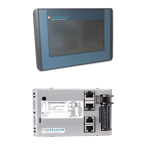
Infranor XtrapulsPac User manual

1
www.infranor.com
DI G I T A L D R I V E F O R S I N U S O I D A L S Y N C H R O N O U S AC M O T O R S
XtrapulsPac
I n s t a l l a t i o n G u i de

2
XtrapulsPac Installation Guide
WARNING
This is a general manual describing a series of servo drives having output capability suitable for driving AC
brushless sinusoidal servo motors.
Please see also:
oXtrapulsPac STO for the Safe Torque Off function
oXtrapulsPac User Guide for the operation of the drive (commissioning, configuration, ...)
oXtrapulsPac Templates for the templates of target applications.
oGem Drive Studio software Quick Start manual for the drive parameterization.
oEtherCAT® fieldbus interface manual for the XtrapulsPac-et version.
oGDPS manual, for the use of the GDPS power supply unit.
Instructions for storage, use after storage, commissioning as well as all technical details require the
MANDATORY reading of the manual before getting the drives operational.
Maintenance procedures should be attempted only by highly skilled technicians having good knowledge
of electronics and servo systems with variable speed (EN 60204-1 standard) and using proper test
equipment.
The conformity with the standards and the "CE" approval is only valid if the items are installed according to the
recommendations of the drive manuals. Connections are the user's responsibility if recommendations and
drawings requirements are not met.
INFRANOR does not assume any responsibility for any physical or material damage due to improper handling or
wrong descriptions of the ordered items.
Any service on the items, which is not specified in the manual, will immediately cancel the warranty.
INFRANOR reserves the right to change any information contained in this manual without notice.
© INFRANOR, July 2016. All rights reserved.
Issue: 2.16
!
Any contact with electrical parts, even after power down, may involve physical damage.
Wait for at least 10 minutes after power down before handling the drives (a residual voltage of several
hundreds of volts may remain during a few minutes).
ESD INFORMATION (ElectroStatic Discharge)
INFRANOR drives are designed for being best protected against electrostatic discharges. However,
some components are particularly sensitive and may be damaged if the drives are not properly stored
and handled.
STORAGE
- The drives must be stored in their original packaging.
- When taken out of their packaging, they must be stored positioned on one of their flat metal
surfaces and on a dissipating or electrostatically neutral support.
- Avoid any contact between the drive connectors and material with electrostatic potential
(plastic film, polyester, carpet…).
HANDLING
- If no protection equipment is available (dissipating shoes or bracelets), the drives must be
handled via their metal housing.
- Never get in contact with the connectors.
WASTE DISPOSAL
This symbol indicates that INFRANOR devices shall be eliminated by selective disposal and not
with household waste.

3
Content
XtrapulsPac Installation Guide
Content
PAGE
CONTENT............................................................................................................................................... 3
CHAPTER 1 –GENERAL ...................................................................................................................... 6
1.1 -INTRODUCTION.......................................................................................................................... 6
1.2 -DESCRIPTION / COMPLIANCE WITH THE STANDARDS......................................................... 7
1.2.1 - General description ............................................................................................................... 7
1.2.2 - Reference to the standards: CE............................................................................................ 7
1.2.3 - Reference to the standards: UL Listing................................................................................. 8
1.3 -OTHER DOCUMENTS................................................................................................................. 8
1.4 -ORDERING CODES..................................................................................................................... 9
1.4.1 - Drives..................................................................................................................................... 9
1.4.1.1 - Ordering code of the drives.............................................................................................................9
1.4.1.2 - Selection of the drive version..........................................................................................................9
1.4.2 - Connector sets..................................................................................................................... 10
1.4.2.1 - Ordering code of the connector sets.............................................................................................10
1.4.2.2 - Connector set description .............................................................................................................10
CHAPTER 2 –SPECIFICATIONS........................................................................................................ 11
2.1 -MAIN TECHNICAL DATA........................................................................................................... 11
2.1.1 - XtrapulsPac-230/I................................................................................................................ 11
2.1.2 - XtrapulsPac-400/08 and 20 A.............................................................................................. 12
2.1.3 - XtrapulsPac-400/45 A, 100 A and 200 A............................................................................. 13
2.1.4 - Technical specifications....................................................................................................... 14
2.1.5 - Cold Plate specifications ..................................................................................................... 16
2.2 -DIMENSIONS AND CONNECTOR LOCATION......................................................................... 18
2.2.1 - XtrapulsPac 230 V dimensions............................................................................................ 18
2.2.2 - XtrapulsPac 230 V: Panel layout dimensions...................................................................... 19
2.2.3 - XtrapulsPac 400 V / 08 to 45 A dimensions........................................................................ 20
2.2.4 - XtrapulsPac 400 V / 100 A dimensions............................................................................... 22
2.2.5 - XtrapulsPac 400 V / 200 A dimensions............................................................................... 24
2.2.6 - XtrapulsPac 400 V / 8 to 100 A Cold Plate dimensions...................................................... 25
2.2.7 - XtrapulsPac 400 V: Panel layout dimensions...................................................................... 26
CHAPTER 3 –INPUTS - OUTPUTS .................................................................................................... 27
3.1 -DISPLAY.................................................................................................................................... 27
3.1.1 - Leds..................................................................................................................................... 27
3.1.2 - XtrapulsPac-ak Version: CANopen® communication bus ................................................. 28
3.1.3 - XtrapulsPac-et version: EtherCAT® communication bus.................................................... 28
3.2 -DRIVE ADDRESSING: SELECTION OF THE TRANSMISSION SPEED.................................. 28
3.2.1 - Pac-ak version: CANopen® communication bus ............................................................... 28
3.2.2 - Pac-et version: EtherCAT® communication bus................................................................. 28
3.3 -X1 CONNECTOR....................................................................................................................... 29
3.3.1 - XtrapulsPac-ak and XtrapulsPac-et versions...................................................................... 29
3.3.1.1 - X1 connector for transmitter resolver input (Sub D 15 pins female)..............................................29
3.3.1.2 - X1 connector for SinCos tracks input (Sub D 15 pins female) ......................................................29
3.3.2 - XtrapulsPac-ed version ....................................................................................................... 30
3.3.2.1 - X1 connector for Hiperface DSL® encoder (Sub D 15 pin female) ...............................................30
3.4 -INPUTS-OUTPUTS CONNECTOR: X2 ..................................................................................... 31
3.4.1 - Specification of the logic inputs........................................................................................... 31
3.4.2 - Specification of the logic output "AOK+/-" (polarized opto-relay output)............................. 32
3.4.3 - Specification of the logic outputs OUT1 to OUT3................................................................ 33
3.4.4 - Specification of the analog inputs ANA1+/- and ANA2 ....................................................... 33
3.4.5 - Specification of the encoder output signals......................................................................... 34
3.4.6 - Specification of the analog output....................................................................................... 34

4
Content
XtrapulsPac Installation Guide
3.5 -ENCODER CONNECTORS: X3.................................................................................................35
3.5.1 - X3 connector for incremental TTL & HES encoder input (Sub D HD 26 pins female).......35
3.5.2 - X3 connector for incremental Sin/Cos & HES encoder input (SubD HD 26 pins female)..35
3.5.3 - X3 connector for "absolute Hiperface® encoder" input (Sub D HD 26 pins female)........... 36
3.5.4 - X3 connector for "single-turn absolute SinCos encoder" input (Sub-D HD 26 pins female)36
3.6 -FIELDBUS CONNECTORS: X6 AND X7....................................................................................37
3.6.1 - XtrapulsPac-ak version (CANopen® bus)........................................................................... 37
3.6.2 - XtrapulsPac-et and XtrapulsPac-ed versions (EtherCAT® bus)......................................... 38
3.7 -SERIAL LINK RS-232 CONNECTOR: X5...................................................................................38
3.7.1 - XtrapulsPac-ak version (CANopen® bus)........................................................................... 38
3.7.2 - XtrapulsPac-et and XtrapulsPac-ed versions (EtherCAT® bus)......................................... 38
3.8 -24 VDC AUXILIARY POWER SUPPLY &MOTOR BRAKE CONNECTOR: X8...........................38
3.8.1 - Motor brake output on XtrapulsPac 400 V drives................................................................ 39
3.8.2 - Motor brake output on XtrapulsPac 230 V drives................................................................ 39
3.9 -POWER CONNECTORS: X9 AND X10....................................................................................... 40
3.9.1 - XtrapulsPac 230 V: X9.........................................................................................................40
3.9.2 - XtrapulsPac 400 V / 45 A and 100 A: X9.............................................................................40
3.9.3 - XtrapulsPac 400 V / 200 A: X9 ............................................................................................41
3.9.4 - XtrapulsPac 400 V / 08 A and 20 A: X10.............................................................................41
3.9.5 - XtrapulsPac 400 V / 08 A and 20 A: X9...............................................................................41
3.10 -MAINS GROUND CONNECTION ............................................................................................42
CHAPTER 4 –CONNECTIONS............................................................................................................ 43
4.1 -EXAMPLES OF CONNECTION DIAGRAMS.............................................................................43
4.1.1 - XtrapulsPac 230 V...............................................................................................................43
4.1.2 - XtrapulsPac 400 V / 08 and 20 A......................................................................................... 46
4.1.3 - XtrapulsPac 400 V / 45 A, 100 A and 200 A........................................................................49
4.1.4 - UL standard requirements ...................................................................................................52
4.1.4.1 - 24 V supply....................................................................................................................................52
4.1.4.2 - Power supply and UL fuse ratings.................................................................................................52
4.2 -ANALOG INPUTS CONNECTION..............................................................................................52
4.2.1 - ANA1 input connection with a differential analog signal source..........................................52
4.2.2 - ANA1 input connection with a non-differential analog signal source...................................53
4.2.3 - ANA2 input connection ........................................................................................................53
4.3 -CONNECTION TO VARIOUS SENSOR TYPES........................................................................ 53
4.3.1 - Connection to a resolver: X1 - Sub D 15 pin female connector ..........................................53
4.3.2 - Connection to an incremental TTL encoder: X3 - 26 pin female HD connector..................54
4.3.3 - Connection to an incremental TTL encoder with Hall sensor: X3 - 26 pin female HD
connector.........................................................................................................................................54
4.3.4 - Connection to an incremental Sin/Cos encoder with Hall sensor: X3 - 26 pin female HD
connector.........................................................................................................................................55
4.3.5 - Connection to an absolute Hiperface® encoder: X3 - 26 pin female HD connector...........55
4.3.6 - Connection to an absolute Hiperface DSL® encoder: X1 - Sub D 15 pin female
connector.........................................................................................................................................56
4.3.7 - Configuration of the XtrapulsPac drive with "Software gearing" function............................58
4.4 -ACCESSORIES AND CONNECTIONS......................................................................................59
4.4.1 - Connection of the internal braking resistor..........................................................................59
4.4.2 - Connection of the external braking resistor.........................................................................60
4.4.3 - Connection of a backup battery........................................................................................... 61
4.5 -CONNECTION TO THE "GEM DRIVE STUDIO"SOFTWARE TOOL........................................61
4.5.1 - Connection of the serial link to the X5 connector................................................................61
4.5.2 - Multiaxis connection of the serial link ..................................................................................61
4.5.2.1 - XtrapulsPac drive in CANopen® configuration..............................................................................61
4.5.2.2 - XtrapulsPac drive in EtherCAT® configuration..............................................................................62
4.6 -WIRING INSTRUCTIONS ..........................................................................................................62
4.6.1 - Ground connection..............................................................................................................62
4.6.2 - Shield connection.................................................................................................................63
4.6.3 - Example of ground and shield connections.........................................................................63
4.6.4 - Motor, resolver and encoder cables ....................................................................................64
4.6.5 - Serial link and CAN communication cables.........................................................................65

5
Content
XtrapulsPac Installation Guide
4.7 -FIRST POWERING OF THE DRIVE.......................................................................................... 65
4.7.1 - Very important ..................................................................................................................... 65
4.7.2 - Connection of the 24 VDC supply........................................................................................ 65
4.7.3 - Connection of the mains power supply ............................................................................... 65
4.7.4 - Starting procedure............................................................................................................... 65
CHAPTER 5 –APPENDIX.................................................................................................................... 66
5.1-ADJUSTMENT TO VARIOUS RESOLVER TYPES................................................................... 66
5.2 -CABINET EXAMPLE.................................................................................................................. 67
5.3 -SOFT START SYSTEM.............................................................................................................. 67
5.3.1 - Introduction.......................................................................................................................... 67
5.3.2 - Integration recommendations.............................................................................................. 68
5.4 -SIZING OF THE BRAKING SYSTEM......................................................................................... 68
5.4.1 - Introduction.......................................................................................................................... 68
5.4.2 - Method for the design of the braking system ...................................................................... 68
5.5 -LOW OPERATING VOLTAGE................................................................................................... 70
5.6 -MAINTENANCE......................................................................................................................... 71
5.6.1 - Procedure after a long time storage.................................................................................... 71
5.6.2 - Warranty.............................................................................................................................. 71
5.7 -OPERATING ENVIRONMENT CONDITIONS........................................................................... 71

6
Chapter 1–General
XtrapulsPac Installation Guide
Chapter 1 –General
1.1 - INTRODUCTION
XtrapulsPac all-digital drives with sinusoidal PWM control are servo drives that provide the control of brushless
AC motors with a position sensor.
The standard control interface can be:
- CANopen®
1
,
- EtherCAT®
2
,
- analog,
- stepper motor emulation,
- logic I/Os.
But the XtrapulsPac range also offers more sophisticated functions such as:
- DS402 including position capture,
- Master/slave and electronic gearing functions,
- Positioner with motion sequencing.
All versions are delivered in standard with the integrated safety function Safe Torque Off (STO) SIL 2.
With its very small dimensions, the XtrapulsPac is available in various designs:
- stand-alone or multi-axis version,
- standard forced air, push-through or cold plate cooling versions.
Series XtrapulsPac drives are fully configurable in order to fit various applications. Both drive versions of the
XtrapulsPac range are described below.
The XtrapulsPac version with CANopen® interface can be used in the following application types:
Axes controlled by CANopen® fieldbus according to the DS402 protocol,
Stand-alone operation as a motion sequencer with control by means of logic I/Os,
Traditional analog speed drive with +/- 10 V command and position output by A, B, Z encoder signal
emulation,
Stepper motor emulation with PULSE and DIR command signals.
The XtrapulsPac version with EtherCAT® interface can be used in the following application types:
Axes controlled by EtherCAT® fieldbus according to the DS402 protocol,
Stand-alone operation as a motion sequencer with control by means of logic I/Os.
The configuration and parameterization software tool Gem Drive Studio allows a quick configuration of the
XtrapulsPac drives according to the target application (template).
1
CANopen®is a registered Community Trademark of CAN in Automation e.V., Germany
2
EtherCAT®is a registered trade mark and a patented technology of Company Beckhoff Automation GmbH,
Germany.

7
Chapter 1 –General
XtrapulsPac Installation Guide
1.2 - DESCRIPTION / COMPLIANCE WITH THE STANDARDS
1.2.1 - General description
The XtrapulsPac drive directly controls the motor torque and speed from of the information provided by a high
resolution position sensor (resolver or encoder). The sinusoidal current commutation generated from the
information of this high resolution position sensor ensures very smooth motor torque/force control.
The XtrapulsPac drive can be configured for the feedback of various position sensor types. The appropriate
position sensor configuration is selectable by software and saved in the drive.
With a resolver sensor feedback, the motor absolute position value over one revolution is available and the
servo motor can immediately be enabled after the drive power up.
With an incremental encoder only, a motor phasing procedure (Phasing) must be executed at each
drive power up before the motor enabling.
With an incremental encoder + Hall Effect Sensors (HES) feedback, the motor phasing procedure is no
more necessary and the servo motor can immediately be enabled after the drive power up.
With an absolute single-turn, multi-turn or linear encoder using the HIPERFACE® communication
protocol and fitted with incremental SinCos outputs, the servo-motor can also be immediately enabled after
the drive powering.
With an absolute single-turn or multi-turn digital encoder using the HIPERFACE DSL® communication
protocol, the servo-motor can also be immediately enabled after the drive powering.
Series XtrapulsPac drives have their own DC/DC converter to provide the voltages required for the drive
operation with a 24 VDC +/- 15 % supply source which is generally available on machines. The auxiliary supply
allows keeping the drive logic supplies after the power supply has been switched off. Thus, the position output
can be kept without new initializations of the machine. A 24 VDC battery supply with specific wiring allows keeping
the position even after switching off the auxiliary 24 VDC supply. This wiring can be used for getting an "absolute"
servo drive operation.
A soft start system limits the inrush current at the mains power on.
All control parameters are programmable via a serial link (e.g. RS-232) and saved in a memory. The auto-tuning
and auto-phasing functions allow a quick and easy commissioning of the drive.
Thanks to the Gem Drive Studio software tool, which is PC compatible with the WINDOWS® operating system, all
drive parameters can be displayed and easily modified.
Gem Drive Studio also allows the quick configuration of the XtrapulsPac drive according to the application type:
as an Analog drive, Stepper motor emulation, Positioner, etc.
The Digital Oscilloscope of this software tool ensures an easy and quick commissioning of the drive.
The Gem Drive Studio software also allows parameterization and diagnostic in a multi-axis configuration.
1.2.2 - Reference to the standards: CE
Electromagnetic compatibility
According to the Directive 2014/30/UE, the actuators are complying with the Electromagnetic Compatibility
standards regarding the power servos, referenced in the EN 61800-3 –Part 3 about "Electrical power servo
systems with variable speed":
EMISSION
EN 61800-3:2004 –Part 3: section 6, 4-2 (C3 category equipment –tables 17 and 18).
IMMUNITY
EN 61000.4-2-3-4.5-6 Expected use: Second environment including other areas than those
directly supplied with electricity by a public low-voltage mains network.

8
Chapter 1–General
XtrapulsPac Installation Guide
NOTE: Industrial areas and technical rooms are examples of second environment.
Security:
Directive 93/68/EEC: Low voltage directive
EN 61800-5-1: (Overvoltage category III, System Voltage = 300 V) Electrical, Thermal and Energetic security requirements
EN 60204-1: Safety of machinery: electrical equipment of machines
UL508C: Power Conversion Equipment
UL840: Insulation coordination for electrical equipment
EN 61800-5-2: Adjustable speed electrical power drive systems:
Safety requirements - Functional
1.2.3 - Reference to the standards: UL Listing
XtrapulsPac series have been “cULus” listed according to UL508C and UL840 regarding the insulation.
XtrapulsPac series were evaluated to:
- the Third Edition of UL508C, the UL Standard for Power Conversion Equipment for the UL Listing
(USL),
- the CSA Standard for Industrial Control Equipment, C22.2 N° 14-10 for the Canadian UL Listing
(CNL).
1.3 - OTHER DOCUMENTS
XtrapulsPac User guide.
XtrapulsPac "Safe Torque Off" specification.
XtrapulsPac Templates.
Gem Drive Studio software Quick Start manual.
EtherCAT® fieldbus interface.
GDPS Power Supply Unit manual.

9
Chapter 1 –General
XtrapulsPac Installation Guide
1.4 - ORDERING CODES
1.4.1 - Drives
1.4.1.1 - Ordering code of the drives
XtrapulsPac- xx –UUU / cc - xx - mm
Drive version
ak:
Analog interfaces and CANopen® fieldbus
et:
ed:
EtherCAT® fieldbus
EtherCAT® fieldbus + digital encoder interface
Voltage range
230:
400:
Voltage range 230 V
Voltage range 400 V
Current ratings for 230 V drives
05 = 5 Arms
11 = 11 Arms
17 = 17 Arms
Current rating for 400 V drives
08 = 08 Arms
20 = 20 Arms
45 = 45 Arms
100 = 100 Arms
200 = 200 Arms
Connector set
00:
Without connector set
FC:
With power + motor connector set
FL:
With command connector set
FCL:
With power + motor + command connector set
Mounting version (400 V range only, except for 200 A)
ST: Standard version
PT: Push-through version
CP: Cold plate version
1.4.1.2 - Selection of the drive version
Feedback sensor
Input command
Analog drive
Stepper emulation
CANopen®
EtherCAT®
Transmitter resolver
Pac-ak
Pac-et
SinCos tracks resolver
TTL encoder + HES
Pac-ak
Pac-et
Pac-ed
SinCos encoder + HES
Absolute single-turn SinCos encoder
Hiperface® with SinCos channels
Hiperface DSL® (single motor cable)
-
Pac-ed

10
Chapter 1–General
XtrapulsPac Installation Guide
1.4.2 - Connector sets
1.4.2.1 - Ordering code of the connector sets
If the connector kit is separately ordered from the drive, please use the following reference:
FXX - Pac - rrr
Connector set type
FL:
With command connector set
FC:
With power + motor connector set
FCL:
With power + motor + command connector set
Rating suffix (not required for FL set)
230
Connector kit for 230 V drives
402
Connector kit for 400 V / 08 A and 20 A drives
404
420
Connector kit for 400 V / 45 A and 100 A drives
Connector kit for 400 V / 200 A drives
1.4.2.2 - Connector set description
FC-Pac
X8: 5 pin plug connector for the auxiliary 24 VDC supply and for the motor brake.
X9: power plug connector for mains and motor.
X10: mains power plug connector for Pac 400 V / 08 to 20 A
FL-Pac
X1: male 15 pin Sub D connector for the resolver, with the appropriate conducting cover.
X2: female 26 pin Sub D HD connector for the logic I/Os, with the appropriate conducting cover.
X3: male 26 pin Sub D HD connector for the encoder, with the appropriate conducting cover.
X5: female 9 pin Sub D connector for the RS232 / CAN link, with the appropriate conducting cover.
FCL-Pac
X1: male 15 pin Sub D connector for the resolver, with the appropriate conducting cover.
X2: female 26 pin Sub D HD connector for the logic I/Os, with the appropriate conducting cover.
X3: male 26 pin Sub D HD connector for the encoder, with the appropriate conducting cover.
X5: female 9 pin Sub D connector for the RS232 / CAN link, with the appropriate conducting cover.
X8: 5 pin plug connector for the auxiliary 24 VDC supply and for the motor brake.
X9: power plug connector for mains and motor.
X10: mains power plug connector for Pac 400 V / 08 A to 20 A

11
Chapter 3 –Inputs-Outputs
XtrapulsPac Installation Guide
Chapter 2 –Specifications
2.1 - MAIN TECHNICAL DATA
2.1.1 - XtrapulsPac-230/I
Design
Stand-alone
Available cooling version
Forced air (standard)
Operating power supply voltage (1)
110 to 230 VAC +/- 10 % single-phase
50 - 60 Hz
Grounded neutral system with balanced phase to
ground voltage
Undervoltage threshold (1)
100 VDC
Braking threshold (1)
390 VDC
Overvoltage threshold (1)
430 VDC
EMC filter on the mains power supply
Fully integrated in the drive
Motor phase-to-phase output voltage
95 % of mains voltage
Integrated braking resistor
100 R / 35 W
External braking resistor (1)
Minimum external resistor: 50 Ω
Infranor ordering code: dp 50/200
Minimum phase-to-phase inductance (1)
1 mH
Galvanic isolated auxiliary supply voltage
24 VDC +/- 15 % - 400 mA (without motor brake)
EMC filter on auxiliary supply
Integrated in the drive
(1) These values correspond to the default configuration of the drive. For lower operating voltage, see Appendix
"Low operating voltage".
OUTPUT CURRENT RATINGS
TYPE
Max.
output
current
for 1 s
(Arms)
+/-5 %
(230 VAC)
Rated
output
current
(Arms)
(230 Vac)
Power
losses
at rated
current
(W)
Rated input
current
(Arms)
(230 Vac,
60 Hz)
Certified max.
protection line
circuit fuses
A60Q
Mains
short-
circuit
power
UL
listed
Pac-230/5
5
2.5
20
4.3
10 A
5 kA
yes
Pac-230/11
11
5.5
40
9.5
15 A
5 kA
yes
Pac-230/17
17
8.5
65
14.7
20 A
5 kA
yes
Maximum surrounding air temperature: 40°C.
Note:
OPERATING POWER RESTRICTION
Maximum continuous RMS power ensuring a capacitor lifetime of 20'000 hours:
- 650 W for ratings 230/05 and 230/11,
- 1000 W for rating 230/17.

12
Chapter 3 –Inputs-Outputs
XtrapulsPac Installation Guide
In applications with higher continuous power, external capacitors (ref. CAPABOX 230) must be added or the DC
buses must be paralleled (see “DC bus interfacing” application note).
The CAPABOX accessory is not UL listed.
2.1.2 - XtrapulsPac-400/08 and 20 A
Design
Stand-alone
Available cooling version
- Forced air (standard)
- Push-through
- Cold Plate
Operating power supply voltage
according to the drive parameters
230 to 480 VAC +/- 10 % three-phase
50 - 60 Hz
Grounded neutral system with balanced phase to
ground voltage.
Undervoltage threshold (1)
210 VDC
Braking threshold (1)
790 VDC
Overvoltage threshold (1)
910 VDC
EMC filter on the mains power supply
Fully integrated in the drive
Motor phase-to-phase output voltage
95 % of mains voltage
Integrated braking resistor
400 R / 35 W
External braking resistor
XtrapulsPac 400/08
Minimum external resistor: 100 Ω (1)
Infranor ordering code: dp 100/100
XtrapulsPac 400/20
Minimum external resistor: 50 Ω (1)
Infranor ordering code: dp 50/200
Minimum phase-to-phase inductance (1)
2 mH
Galvanic isolated auxiliary supply voltage
24 VDC +/- 15 % - 400 mA (without motor brake)
EMC filter on auxiliary supply
Integrated in the drive
(1) These values correspond to the default configuration of the drive. For lower operating voltage, see Appendix
"Low operating voltage".
OUTPUT CURRENT RATINGS
TYPE
Max. output
current for
1 s (Arms)
+/-5 %
(480 VAC)
Rated
output
current
(Arms)
(460 VAC)
Power
losses
at rated
current
(W)
Rated input
current
(Arms)
(480 VAC,
60 Hz)
Certified max.
protection line
circuit fuses
A60Q
Mains
short-
circuit
power
UL
listed
Pac-400/08
8
4
65
3.8
5 A
5 kA
yes
Pac-400/20
20
10
155
9.4
10 A
5 kA
yes
Maximum surrounding air temperature: 40°C.

13
Chapter 3 –Inputs-Outputs
XtrapulsPac Installation Guide
2.1.3 - XtrapulsPac-400/45 A, 100 A and 200 A
Design
Multi-axis
Available cooling versions
- Forced air (standard)
- Push-through (except for 200 A current rating)
- Cold Plate (except for 200 A current rating)
Operating power supply voltage
according to the drive parameters
100 to 800 VDC
Undervoltage threshold (1)
210 VDC
Overvoltage threshold (1)
910 VDC
EMC filter on the mains power supply
External
Motor phase-to-phase output voltage
95 % UDC/2 Vrms
Minimum phase-to-phase inductance (1)
2 mH
Galvanic isolated auxiliary supply voltage
24 VDC +/- 15 % - 500 mA (without motor brake)
EMC filter on auxiliary supply
Integrated in the drive
(1) These values correspond to the default configuration of the drive. For lower operating voltage, see Appendix
"Low operating voltage".
OUTPUT CURRENT RATINGS
TYPE
Max. output current
for 1 s (Arms) +/-5 %
(480 VAC)
Rated output
current (Arms)
(460 VAC)
Power losses
at rated current
(W)
Rated input
current (Arms)
(680 VDC)
UL
listed
Pac-400/45
45
22.5
345
26.3
yes
Pac-400/100
100
35
535
41
yes
Pac-400/200
200
75
1147
87.9
Complying
with the UL
standard
Maximum surrounding air temperature: 40°C.

14
Chapter 3 –Inputs-Outputs
XtrapulsPac Installation Guide
2.1.4 - Technical specifications
Servo loops: current, speed, position
Digital
Position sensor
Transmitter resolver (only Pac-ak and Pac-et versions)
Sin and Cos tracks
Incremental encoder (TTL or SinCos signals)
Incremental encoder + Hall Effect sensors
Absolute single-turn SinCos encoder
Absolute Hiperface® encoder
Absolute Hiperface DSL® encoder (Pac-ed version only)
Power protections
See section 3.1.1 - LEDs
Switching frequency
8 kHz
Analog input 1
+10 V (resolution: 12 bit)
Analog input 2
0 to +10 V (resolution: 12 bit)
Speed and position regulators
Sampling period = 0.5 ms
Anti-wind-up system of the integrator
Anti-resonance filter
Adjustable digital gains
Speed loop bandwidth
Selectable cut-off frequency for 45° phase shift:
50 Hz (low), 75 Hz (medium) or 100 Hz (high)
Current loop bandwidth
Cut-off frequency for 45° phase shift:
500 Hz (low) or 1000 Hz (high)
Max. motor speed
Adjustable from 100 to 25'000 rpm
Drive reaction time
(initialization delay before PWM on)
XtrapulsPac 230 V: 6.25 ms
XtrapulsPac 400 V: 20 ms
Encoder position output for CANopen®
version.
No encoder output available on
EtherCAT® version
Quadrature signals A & B with Z marker pulse.
RS 422 line transmitter: 20 mA per output
Programmable resolution: 64 ppr to 16384 ppr (according to
max. motor speed).
Max. pulses frequency: 437 kHz
Accuracy in arc minutes = (8 + 5400/resolution)
Note: the total position accuracy must take into account the
accuracy of the resolver used.
Resolver input
Software selectable:
Transmitter resolver:
Excitation frequency: 8 kHz
Max. output current = 30 mA
Transformation ratio: 0.3 to 0.5 (other values are factory set)
SinCos tracks:
1 Vcc to 4 Vcc Sin and Cos signals

15
Chapter 3 –Inputs-Outputs
XtrapulsPac Installation Guide
Encoder input
Software selectable:
Quadrature signals A & B + one Z marker pulse per revol.
Line receiver RS-422
Max. frequency of encoder pulses: 1 MHz
Resolution: 500 to 106 ppr
Incremental Sin/Cos encoder
Heidenhain 1 Vcc Sin/Cos type or compliant
Maximum signal frequency: 200 kHz
Resolution: 500 to 106 ppr
Interpolation factor: 256
Absolute single-turn Sin/Cos encoder
Heidenhain ERN 1085 or compliant
Maximum signal frequency: 200 kHz
Resolution: 512 to 2048 ppr
Interpolation factor: 256
Hiperface® standard with SinCos channels
Maximum signal frequency: 200 kHz
Resolution: 16 to 2048 ppr
Interpolation factor: 256
Hiperface DSL® standard
Pulse & Direction input
Software re-configuration of 2 logic inputs for stepper motor
emulation. 3 selectable channels:
- Optocoupled 24 V logic (max. pulse frequency = 10 kHz)
- Non optocoupled 5 V to 24 V
(max. pulse frequency = 50 kHz)
- RS422 differential receiver (max. pulse frequency = 1
MHz)
Resolution (steps per motor revolution): programmable.
Hall sensors input
5 V to 24 V positive logic voltage accepted
External HES supply voltage required if different from 5 V
HES sequence error detection
7 opto-isolated logic inputs
5 software configurable logic inputs
2 inputs dedicated to the STO (Safe Torque Off) function
"Amp OK" output
"OptoMos" relay: output open if fault
Umax = 50 V, Imax = 300 mA
Motor brake output
XtrapulsPac 230 V: not available / Use of the digital output
XtrapulsPac 400 V / 08 to 20 A: 24 VDC / 1.5 A
XtrapulsPac 400 V / 45 to 200 A: 24 VDC / 2.5 A
3 parameterizable logic outputs
Type PNP "high side" 24 VDC, max. 300 mA
Analog output
2.5 V +/-2.5 V, resolution: 8 bit, load: 10 mA
Low-pass filter: 160 Hz, programmable output signal: all
objects can be mapped.
Error display
Front panel LEDs + diagnostic via serial link or CAN bus
Motor and application parameterization
Serial link RS-232 or
bus interface with CANopen® communication protocol
CAN interface
CANopen® Protocol (DS301, DSP402)
EtherCAT® interface
See EtherCAT® Fieldbus Interface manual
Automatic functions
Drive adjustment to the motor (AUTO-PHASING)
Adjustment of the servo loops (AUTO-TUNING)

16
Chapter 3 –Inputs-Outputs
XtrapulsPac Installation Guide
MTBF (Mean Time Between Failures)
> 100'000 hours
Maximum surrounding air temperature
- Operation: +5°C to +50°C: from 40°C, the rated current
must be reduced by 3 % per additional Celsius degree
- Storage: -20°C to +70°C
Altitude
1000 m
Moisture
< 50 % at 40°C and < 90 % at 20°C: EN 60204-1 standard
Condensation prohibited (storage and operation)
Cooling
Natural air convection or forced air according to the current
rating.
Check for free air convection and for no obstruction of the
upper or lower air admissions.
Environment
Open chassis to be mounted inside a cabinet protecting the
drive from conducting dust and condensation (pollution
degree 2 environment) and according to the room
temperature requirements.
Mounting position
Vertical
Weight
Pac-230/05, 11 and 17: 1.5 kg.
Pac-400/08 and 20: 2.2 kg.
Pac-400/45: 2.4 kg.
Pac-400/100: 3.3 kg
Pac-400/200: 8.5 kg
2.1.5 - Cold Plate specifications
Heatsink requirements:
The heat transfer is ensured by an external heatsink that can work with various techniques (air, liquid, …).
For a proper running of the drive, the following specifications shall be fulfilled:
- The contact surface between the drive and the heatsink shall be at least as large as the drive plate.
- The planarity of the heatsink shall be better than 0.05 mm all over the rear of the drive.
- The temperature of the heatsink should never exceed 70°C.
- Maximum surrounding air temperature :
o50°C
oFrom 40°C, the rated current must be reduced by 3 % per Celsius degree.
- A short preview of the maximum values for the thermal resistor of the heatsink is given in the following table:
Continuous motor
current (A)
Losses (W)
at 400 VAC
RTH
(K/W)
4
56
0.55
10
140
0.22
22.5
314
0.10
35
489
0.06
The file "Infranor thermal utility" is available for free download on the Infranor website www.infranor.com for more
detailed estimations.

17
Chapter 3 –Inputs-Outputs
XtrapulsPac Installation Guide
Mounting instructions:
- Clean the contact surface of the heatsink with alcohol.
- Apply a thermal interface between the drive plate and the heatsink. Recommended thermal interfaces:
oA thin layer of thermal paste on the drive (recommended reference: RHODORSIL Paste 340).
oPhase change thermal interface (recommended reference: Bergquist, Hi-Flow 225F-AC,
15050 mm)
- Fasten the drive with 4 screws and tooth lock washers.

18
Chapter 3 –Inputs-Outputs
XtrapulsPac Installation Guide
2.2 - DIMENSIONS AND CONNECTOR LOCATION
2.2.1 - XtrapulsPac 230 V dimensions
Dimensions are given in mm.
BOTTOM VIEW
SIDE VIEW FRONT VIEW
TOP VIEW

19
Chapter 3 –Inputs-Outputs
XtrapulsPac Installation Guide
2.2.2 - XtrapulsPac 230 V: Panel layout dimensions
Dimensions are given in mm
Description
Symbol
XtrapulsPac
Minimum top and bottom clearance
A
50
Minimum side clearance
B
10
Recommended pitch
D
80
VERTICAL MOUNTING IS MANDATORY

20
Chapter 3 –Inputs-Outputs
XtrapulsPac Installation Guide
2.2.3 - XtrapulsPac 400 V / 08 to 45 A dimensions
Dimensions are given in mm.
Standard version
BOTTOM VIEW
SIDE VIEW FRONT VIEW
TOP VIEW
Note:
This bottom view is the one of the 400/45 drive
(without X10 connector).
The X10 connector is only available
on drives with 8 A and 20 A current ratings.
Other manuals for XtrapulsPac
1
Table of contents
Other Infranor Controllers manuals