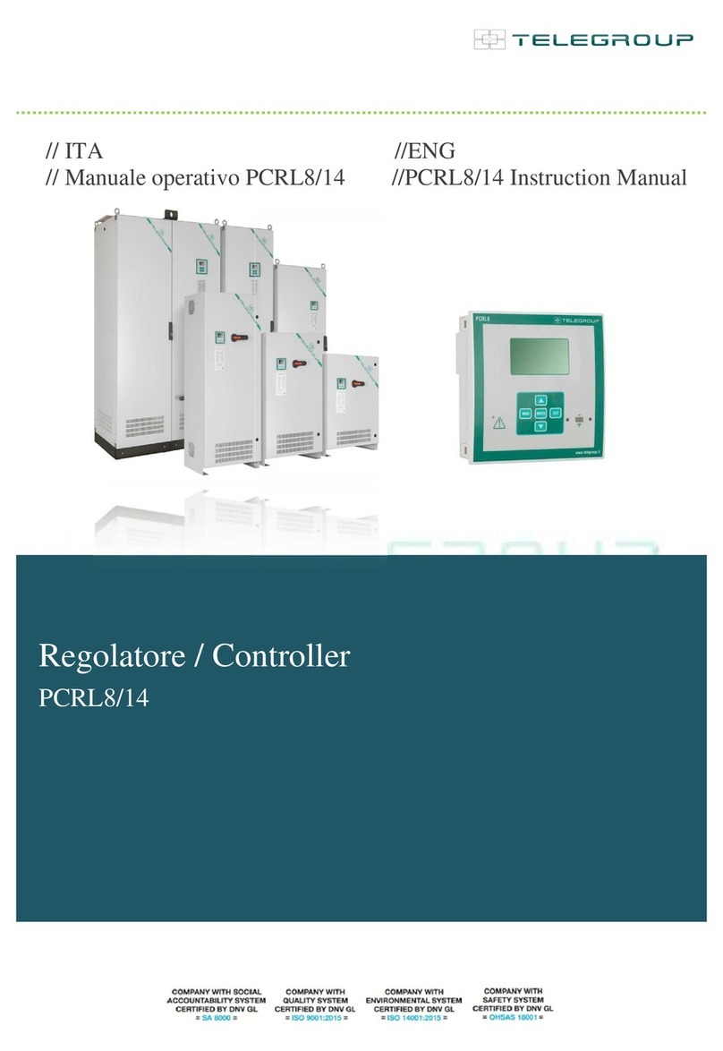
Telegroup PCRL8/14 User manual

// ENG
// User Manual
// PFC Controller
J
Automatic PFC systems
all Series
PC
PCRL8/14
Automatic PFC systems

p. 2 / 43
REVISION INDEX
REVISION DATE DESCRIPTION
01 01/07/207 REVISION UPDATE
02 17/09/2018 REVISION UPDATE
©2018 Telegroup S.r.l.
The contents of this manual are protected by copyright
owned by the publisher; reproduction is forbidden (also
partial) without authorization.
The information contained in this manual is accurate,
but we accept no responsibility for any errors or errors
omissions. The manufacturer also reserves the right to make
design changes
Identification Technical editing Verified by Approved by
MUM- TL TLF
Ing. Lorenzo Cassaresi
____________________
Ing. Massimo Cassaresi
___________________
Sig. Fabiano Bagnoli
________________

p. 3 / 43
INDEX
1. INTRODUCTION 5
1.1. Purpose of the Instruction Manual 5
1.2. Recipients 6
1.3. Storage of the Instruction Manual 6
1.4. Definitions and pictograms 6 ... 7
2. SAFETY INSTRUCTIONS 8
2.1. Transport and storage 9
2.2. Positioning 9
2.3. Installation 9
2.4. Operation and Maintenance 10
3. GENERAL INFORMATION 10
3.1. Manufacturer Identification 10
3.2. Product Identification 10
3.3. Statement 11
3.4. Safety Standards 12
3.5. Warranty 12
4. GENERAL DESCRIPTION OF THE PANEL 13
4.1. Environmental conditions 13
4.2. Electromagnetic environment 13
4.3. Technical data of the equipment 14
4.4. Sound emissions 14
5. INSTALLATION 14
5.1. Inspection of the unit 14
5.2. Connection 14 ... 14
6. ADJUSTMENTS 17
6.1. Operating instructions for the PCRJ8 controller 18 ... 59
7. DISPOSAL 60
8. USE OF THE DEVICE 61
8.1. Intended use 61
8.2. Contraindications for use 61
9. MAINTENANCE 62
9.1 Ordinary and extraordinary maintenance 62..64
9.2 Assistance 65
10. EMERGENCY SITUATIONS 65

p. 4 / 43
ANNEX
Wiring Diagram
Declarations of conformity
Test certificate
Warranty certificate

p. 5 / 43
1. INTRODUCTION
1.1. Purpose of the Instruction Manual
This instruction manual is an integral part of the entire range of automatic power factor correction panels
and is intended to provide all the information necessary for:
Know the product and its operation
Know the expected operating modes and limits of use
To sensitize operators correctly to security issues;
The correct installation;
Its correct and in safety conditions;
Perform scheduled maintenance operations correctly and safely;
To dismantle the product in safety conditions and in compliance with the regulations in force to protect
the health of workers and the environment
The managers of the company departments, where this machine will be installed, have
the obligation, according to current regulations, to read carefully the contents of this
document and to make it read to the conductors and maintenance workers, for the
parts that to them
compete. The time spent for this purpose will be largely rewarded by the correct
operation of the machine and its use in safety conditions
This document assumes that in the places, where the product has been destined, the current rules of safety and
hygiene of the work are observed.
The instructions, drawings and documentation contained in this Manual are of a reserved technical nature, strictly
owned by the manufacturer and can not be reproduced in any way, either fully or partially.
The Instruction Manual must accompany the product for its life time in all the passages of property that the same
may have therefore must be favored a good conservation handling it with care, avoiding contact with fats, dirt and
aggressive substances.
The manual must be kept intact, must not be removed, torn or arbitrarily modified any of its parts, must be stored in
an environment protected from moisture and heat, in the vicinity of the product to which it refers.
The first page shows the revision index of the instruction manual with the descriptions of the changes made in the
various revisions.
The sequence of the chapters responds to the temporal logic of the product life.
Telegroup S.r.l. having the responsibility to ensure that they are actually present in the points of use, only the
updated versions of the Manual make available the updated versions of the manual on the Site www.telegroup.it.

p. 6 / 43
1.2 Recipients
The manual in question is addressed to Installers, Operators, Maintenance Managers and to all personnel
who can intervene or interface with the machine at any level.
It is divided into autonomous chapters aimed at specific figures for which the skills have been defined,
necessary to operate on the machine in safe conditions.
The machine is an appliance intended for industrial use, and therefore professional and not generalized, so
its use can only be entrusted to qualified technical personnel who:
has reached the age of majority (18),
both physically and mentally fit to perform work of particular technical difficulty,
has been adequately instructed on the use and maintenance of the machine,
has been judged by the entrepreneur to perform the task assigned to him,
be able to understand and interpret the operator's manual and safety instructions,
know the emergency procedures and their implementation,
possess the ability to operate the specific type of equipment,
is familiar with the specific rules of the case,
understood the operating procedures outlined by the manufacturer.
1.3 Storage of the instruction manual
The Instruction Manual must be kept with care and must accompany the product in all the steps of
ownership.
Storage should be taken care of with dirty care.
They must be removed, torn or arbitrarily modified from the parts.
The Manual should be stored in an environment protected from humidity and heat and in the vicinity of the
product to which it refers.
1.4 Definitions and pictograms
To facilitate the immediacy of the comprehension of the text in this paragraph the meaning of terms, abbreviations
and pictograms used in the manual is clarified. Their use allows to quickly and univocally provide the information
necessary for the correct use of the machine in safety conditions.
INSTALLER: One who mounts and installs a machine and follows the entire process that goes from the arrival to
the destination of the components to the subsequent installation at the customer, to final testing and signing of
acceptance documents, possibly coordinating a team of men with specializations different.
The figure, in detail, has the task of:
assemble the machine following the drawing and using the components at its disposal;
provide, during installation at the customer's site, the setting up and adjustment of the machine or system;

p. 7 / 43
OPERATOR: The person in charge of installing, operating, regulating, cleaning, repairing and moving a machine
and carrying out its maintenance;
DANGER: A potential source of injury or damage to health;
HAZARDOUS AREA: Any area inside and / or near a machine where the presence of a person constitutes a risk to
the safety and health of that person;
EXPOSED PERSON: Any person who is completely or partially in a dangerous area;
RISK: Combination of the likelihood and severity of an injury or damage to health that may arise in a dangerous
situation;
PROTECTIVE DEVICE: Device (other than a guard) which reduces the risk, alone or associated with a guard;
INTENDED USE: Use of the machine according to the information provided in the instructions for use;
USE INCORRECTLY REASONABLE FORCE: Use of the machine in a manner different from that indicated in the
instructions for use, but which may derive from easily predictable human behavior.
RESIDUAL RISK: Risks that remain, despite the integrated protection measures adopted in the machine design
and in spite of the protections and protection measures
complementary measures adopted.
SAFETY COMPONENT: Component:
intended to perform a security function;
whose failure and / or malfunction jeopardizes the safety of persons. (eg lifting gear, fixed, movable, adjustable,
etc. protector, electrical, electronic, optical, pneumatic, hydraulic device, which asserts, ie interlock, a protector,
etc.).
PICTOGRAMS
The descriptions preceded by this symbol contain very important information /
requirements, particularly with regard to safety. Failure to comply may result in
dangers for the safety of the operators;
PICTOGRAMS RELATED TO SECURITY
• The pictograms in a triangle indicate DANGER.
• The pictograms contained in a circle impose a PROHIBITION / OBLIGATION.

p. 8 / 43
SYMBOL DESCRIPTION
Dangerous electrical voltage
Generic danger
Read the instructions first
2. SAFETY INSTRUCTIONS
Before installing and starting the unit, carefully read the following user manual and safety instructions
To reduce the risk of an electric shock, perform assembly in a controlled temperature and humidity
area free of conduction contaminants.
Disconnect all connections before maintenance or repair. Before maintenance, repair or transport,
completely unplug the unit and disconnect all plugs or connectors.
2.1 Transportation and storage
Telegroup S.r.l. assumes no responsibility if the equipment is moved without the appropriate packaging,
which however does not ensure impermeability to water, dust and aggressive chemical agents
Transport the machine with lifting equipment suitable for the dimensions and weight of the machine.
Always keep in vertical position.
The appliance must always be stored inside.
During transport and storage refers to the following temperature range: -20 to + 50 ° C and, for short
periods not exceeding 24 hours, up to + 70 ° C.

p. 9 / 43
2.2 Positioning
Transferring the panel directly from a cold to a warm environment can cause condensation. Before
being installed it must be absolutely dry. Please allow an acclimatization time of at least two hours.
Do not install near water or in damp environments.
Do not install in places near heat sources.
At least 40 cm must be left to promote heat dissipation. of free space around the walls of the
equipment, naturally excluding the rear one. It is also necessary to allow the natural
circulation of air inside the cabinets, avoiding carefully placing anything against the cooling
openings.
2.3 Installation
Do not operate the equipment in the presence of flammable gases or fumes. The activation of any
electrical equipment in such an environment constitutes a safety risk. Do not place the machine in an
unventilated area.
The power factor correction panel must be installed according to the instructions in this manual. Failure to
recognize the risks related to electricity could prove fatal. Please keep this instruction manual for future
reference.
User operations
The only operations allowed to the user are the following:
Activating and deactivating the unit
Use of user interfaces
Connecting the cables
These operations must be performed according to the instructions provided in this manual.
During any operation, the user must pay the utmost attention and perform only what is indicated in the
instructions. Any deviation from the instructions can be dangerous for the operator.
Position any cables so that no one can step on them or trip over them.
The machine must be operated by experienced personnel.
Never intervene on the live device,
if you also switch off without tension, use safety gloves.
Do not keep accumulated materials of any kind in the vicinity so as not to hinder the cooling of the
equipment.
In case of maintenance or failure, report with a special sign that prohibits the insertion into the network.

p. 10 / 43
2.4 Operation and Maintenance
For complete disconnection of the system: if there are batteries of capacitors inserted, proceed with
their disconnection, following the instructions of "MAN mode". Open the main switch and wait at least
3 minutes for a complete discharge of the capacitors
Ensure that no foreign objects or fluids can enter the equipment.
This equipment operates at dangerous voltages, repairs must only be performed by qualified service
personnel
Disconnect the mains power supply before carrying out any service or repair. Check that there is no
dangerous voltage inside.
3. GENERAL INFORMATION
3.1 Identification of the manufacturer
MANUFACTURER
Telegroup S.r.l.
Via L. Da Vinci, 100 - Loc. Sambuca
50028 TAVARNELLE VAL DI PESA (FI) - ITALIA
CONTACTS
Tel. 055-8071267 / 8071118
Fax 055-8071338
e-mail: telegroup@telegroup.it
www.telegroup.it
3.2 Product Identification
The panel is identified by a CE plate on which the reference data are indelibly marked.

p. 11 / 43
3.3 Statement
Telegroup S.r.l. has produced the product in compliance with the relevant Community Directives applicable at the
time of its placing on the market / first commissioning, has satisfied the relevant requirements from the applicable
directives and has provided the self-certification path for the affixing of the CE marking. Attached is a copy of the
Machine Declaration of Conformity.
Commissioning
The product can only be put into service if properly installed, maintained in efficiency and used in accordance with the
intended use. It is also forbidden to use it following constructive changes or additions
of other components that do not fall into ordinary or extraordinary maintenance without the product being declared again in
compliance with the requirements of the reference directives and the regulations in force.
3.4 Safety Standards
The panel was created taking into account the indications given in the safety technical standards listed below:
Directive 2014/35/UE Concerning the approximation of the laws of the Member States relating to electrical
equipment intended to be used within certain voltage limits
Directive 2014/30/UE Concerning the approximation of the laws of the Member States relating to electromagnetic
compatibility and repealing Directive 89/336 / EEC
CEI EN 61921 Power capacitors. Low voltage PFC batteries
3.5 Warranty
The product is covered by warranty, as provided for in the general sales conditions. If during the period of validity
malfunctions or faults of parts of the product occur, which fall within the cases indicated by the warranty, the
Manufacturer, after the appropriate checks, will repair or replace the defective parts.
In order to take advantage of repairs under warranty, the purchaser must in any case ship the appliance to the
manufacturer (Telegroup Srl Loc. Sambuca 50028 Tavarnelle Val di Pesa (FI)). The costs for shipping the product
to be repaired or replaced are the responsibility of the purchaser; these products are therefore supplied ex-works of
the seller.
The warranty right lapses if the faults claimed result from incorrect behavior and operations that do not comply with
the indications given in this manual, caused by the purchaser, by his employees, by third parties or by improper use
of the product:

p. 12 / 43
incorrect power supply
incorrect installation
natural events (Lightning etc. ..)
It is recalled that modifications to safety devices and systems and any intervention other than ordinary and
extraordinary maintenance, carried out without the express written authorization of the manufacturer, render the
warranty void and relieve the manufacturer from any liability for damage caused by the defective product.
For all these reasons we advise our customers to always contact our Customer Service.
For all components not manufactured by the Seller the warranty conditions of the manufacturers are valid.
With the repair or replacement of any defective parts, the seller's obligation must be deemed to have been
fulfilled, thus remaining exempt from any claim for damages.
4 GENERAL DESCRIPTION OF THE PANEL
Sheet metal cabinet FE P02 epoxy powder coated gray RAL7035 with smooth / textured finish, equipped with
slots for forced cooling of the air.
Front door for access to the internal parts interlocked to the main switch by means of a door-locking
handle; closing by locks.
Blind flange for cable passage located on the upper / lower part of the equipment.
Fixing of the equipment to the floor / wall.
General switch-disconnector with door lock and (pre-opening microswitch: switches the capacitors off, via
contactors, before the isolator contacts open - optional -).
Other features see (APPENDIX).
4.1 Environmental Conditions
The machine is suitable for operating in environments that are:
• altitude not exceeding 1000 m s.l.m .;
• temperature between 0 ° C and + 40 ° C with relative humidity not higher than 85%
It is forbidden to use the machine in environments that are:
• Excessively dusty;
• in corrosive atmosphere;
• at risk of fire;
• in an explosive atmosphere.
4.2 Electromagnetic environment
The machine is designed to operate correctly in an industrial-type electromagnetic environment, within the limits of
Emission and Immunity provided for by the following harmonized standards:
CEI EN 61000-6-2 Electromagnetic compatibility (EMC) Generic standards - Immunity for industrial environments
CEI EN 61000-6-4 Electromagnetic compatibility (EMC) Generic standards - Emission for industrial environments

p. 13 / 43
4.3 Technical data of the equipment
On the product identification plate, the essential technical data are shown (General characteristics, Characteristics
of capacitors Characteristics of power factor correction regulators),
4.4 Sound Emissions
The A-weighted equivalent continuous sound pressure level in the work stations does not exceed 45 db (A) during
the working phase;
5 INSTALLATION
5.1 Inspection of the unit
Upon receipt of the equipment it is advisable to remove the product from the packaging and check for any damage
caused by transport. If damage is found, inform the carrier responsible for the transport and your dealer. Keep the
packing carton in case the product has to be sent back to the factory for repairs.
5.2 Connection
Caution!!! The correct connection and commissioning of an automatic power factor correction device is relatively
simple, but must not in any way be entrusted to the case. As a result, the unit will not switch the capacitor banks on
or off or it will function abnormally. Since the panels are all tested and tested on site, any operating anomalies will
be due to incorrect connection and, in particular, to the incorrect positioning of the current transformer. Please
therefore follow the instructions in this manual to be followed strictly in the sequence indicated.
Thanks for your collaboration
Place the panel in a ventilated position away from sources of heat: good air circulation is one of the most important
characteristics for a correct and lasting operation. Leave a minimum space of 40 cm around the panel, so that the
air can penetrate and exit freely. Do not place the equipment in humid and dusty places unless it has been
requested with a particular degree of protection.
To assure the short-circuit withstand, it is necessary to install a three-phase fuse current regulators of the NH-aM
type, or other devices with similar characteristics, upstream of the power factor correction boards,
both with fixed current and breaking capacity higher than the supposed short-circuit current.
When Icc is not known at the installation point, the short-circuit current at the transformer secondary can be roughly taken.

p. 14 / 43
Power KVAR Icc max kA KVA Vcc% Icc kA
Da 7.5 a 40 1.5 50 4 1,8
Da 45 a 55 2.5 63 4 3,6
Da 65 a 75 8 100 4 5,77
Da 87.5 a 250 15 160 4 7,22
Da 275 a 400 20 200 4 9,02
Da 450 a 750 50 250 4 11,37
315 4 14,43
400 4 18,04
500 4 22,73
630 4 19,25
800 6 24,06
1000 6 30,07
1250 6 38,49
1600 6 48,11
2000 6 50,14
To connect an automatic PFC panel to the network, it is necessary to have a C.T. (current
transformer) having a secondary rated current of 5 or 1 A not supplied with the product but charged
to the customer.
The primary rated current of the C.T. must be chosen according to the rated current of the line
regardless of the power of the power factor correction bearing in mind that the measuring range of the
regulator current ranges from 8% to 110% of the current of the C.T. therefore, this condition must be met.
Eg: there is a circulating current of 200 / A. A T.A. will have to be chosen. whose current ranges from: 2500 A (8%
of 2500 = 200 / A) and 180A (110% of 180 A = 200 / A). It is a good rule to install a C.T. with a double primary
current that is actually circulating, therefore, in the case of the example, a C.T. will be selected. with
primary current of 400 A.
To connect the equipment to the network some simple operations are necessary that must be absolutely respected.
The sequence of the main operations necessary for this purpose can be summarized as follows:
1. Ground the secondary of C.T ..
2. Supply the equipment with cables of adequate cross-section according to the rated power.
3. Power supply: three-phase + Pe (unless otherwise requested)
4. Anchor the power cables to the main switch according to the phase sequence.
If you want to switch off the panel during operation, make sure, before opening the main switch, that you have
disconnected all the batteries, following the instructions (see MAN mode)
• The C.T. must be positioned on the phase (R - L1), upstream of the loads and the line that feeds the power
factor correction panel.

p. 15 / 43
• The phase sequence (R (L1) - S (L2) -T (L3)) must be respected when connecting the line to the power factor
correction panel.
• This condition can be easily checked with the aid of a voltmeter: by measuring, between the phase where the C.T.
(the R) and the phase anchored on the R terminal of the automatic power factor correction switch, the voltage
must be "0".
•The positioning of the C.T. It is essential for the correct functioning of the appliance. The relative diagram
is shown in the figure alongside
The following are some possible positions of the C.T.
wrong:
Position 2: despite being the C.T. installed upstream, and
installed on phase L3 (T) instead of L1 (R)
Position 3: the C.T is installed on the load line!
Position 4: the C.T. it is installed on the phases that feed
the pfc!

p. 16 / 43
The insertion of an automatic power factor correction device in the presence of MV transformers. If there are
batteries of capacitors of the fixed type, on the transformers, the C.T. necessary for the control of the automatic
rephasing device to be placed downstream of the fixed capacitors.
The figure shows the connection of a power factor correction equipment in the presence of MV connected
transformers in parallel
NOTE. It is necessary to use a C.T. adder with 2 or 3 inputs depending on whether there are 2 or 3
transformers, to which the cables coming from the C.T .. must be connected. The output of the C.T. adder must
be connected to the automatic rephasing.
Set the C.T. (the ways to set this parameter are described in Appendix B) as the sum of the two or three C.T
6 ADJUSTMENTS
6.1 INSTRUCTIONS FOR USE OF THE PCRL5/7 POWER FACTOR REGULATOR
The PCRL8/14 is an automatic rephasing controller based on a microprocessor control circuit, able to
perform the insertion or disconnection of the capacitor banks necessary to reach and maintain the
average power factor set. The instrument makes a measurement with RMS value that allows operation
and correct display even in the presence of distorted waveforms. The central microprocessor unit
manages all the regulation procedures

p. 17 / 43
• Automatic microprocessor power factor regulator.
• LED display, 3-digit 7 segments.
• 4-button membrane keyboard.
• TTL-RS232 serial interface for set-up and automatic test by PC.
• Internal temperature sensor.
• Advanced functions (capacitor overload current measurement, average weekly power factor,
maximum value storage).
The appliance is set up to recognize the current direction of the C.T .. In case of cogeneration plants it
is necessary to disable this function (see advanced menu chapter) and to ensure the correct connection
of the C.T ..
The secondary of C.T. it must be connected to the ground.
A. Attention: the parameters of the PCRL8controller are already preset and must not be
changed.
B. The only parameters to be set by the installer are the language and the value of the primary of
the amperometric transformer (C.T). Pay close attention to the setting before pressing the
confirmation button.

Via L. Da Vinci, 100, 50028, Tavarnelle V.P. – Loc. Sambuca (FI) – ITA, P.IVA 0438 634 0485
Ph +39 0558071267 Fax.+ 39 0558071338 telegroup@telegroup.it www.telegroup.it
PCRL8/14 PCRL8/14
Regolatore automatico Automatic Power Factor
del fattore di potenza Controller
MANUALE OPERATIVO INSTRUCTIONS MANUAL
● Prima di qualsiasi intervento sullo strumento, togliere tensione dagli ingressi di misura e di
alimentazione e cortocircuitare i trasformatori di corrente.
●Il costruttore non si assume responsabilità in merito alla sicurezza elettrica in caso di utilizzo
improprio del dispositivo.
●I prodotti descritti in questo documento sono suscettibili in qualsiasi momento di evoluzioni o di
modifiche. Le descrizioni ed i dati a catalogo non possono pertanto avere alcun valore
contrattuale.
● Un interruttore o disgiuntore va compreso nell’impianto elettrico dell’edificio. Esso deve
trovarsi in stretta vicinanza dell’apparecchio ed essere facilmente raggiungibile da parte
dell’operatore. Deve essere marchiato come il dispositivo di interruzione dell’apparecchio: IEC/
EN 61010-1 § 6.11.2.1.
● Pulire lo strumento con panno morbido, non usare prodotti abrasivi, detergenti liquidi o solventi.
● Before any maintenance operation on the device, remove all the voltages from measuring
and supply inputs and short-circuit the CT input terminals.
● Products illustrated herein are subject to alteration and changes without prior notice.
● Technical data and descriptions in the documentation are accurate, to the best of our
knowledge, but no liabilities for errors, omissions or contingencies arising there from are
accepted.
● A circuit breaker must be included in the electrical installation of the building. It must be
installed close by the equipment and within easy reach of the operator.
It must be marked as the disconnecting device of the equipment:
IEC /EN 61010-1 § 6.11.2.1.
●Clean the instrument with a soft dry cloth; do not use abrasives, liquid detergents or
solvents.
Indice
Pagina
Introduzione
1
Descrizione
2
Funzione dei tasti frontali
2
Indicazioni sul display
2
Modi operativi
3
Misure
4
Blocco tastiera
5
Espandibilità
5
Porta di programmazione IR
6
Impostazione parametri da PC, tablet o smartphone
7
Impostazione parametri da pannello frontale
7
Impostazione rapida TA
8
Tabella dei parametri
9
Allarmi
13
Descrizione degli allarmi
13
Proprietà di
default allarmi
14
Menu comandi
15
Utilizzo dongle CX02
16
Installazione
16
Schemi di collegamento
17
Disposizione morsetti
18
Dimensioni meccaniche e foratura pannello
19
Caratteristiche tecniche
19
Cronologia revisioni manuale
20
Index
Page
Introduction
1
Description
2
Keyboard functions
2
Display indications
2
Operating modes
3
Measures
4
Keypad lock
5
Expandability
5
IR programming port
6
Parameter setting
with PC, tablet or smartphone
7
Setting of parameters (setup) from front panel
7
Rapid CT setup
8
Parameter
table
9
Alarms
13
Alarm description
13
Default alarm properties
14
Command menu
15
CX02 dongle usage
16
Installation
16
Wiring diagrams
17
Terminal
position
18
Mechanical dimensions and
p
anel cutout
19
Technical carachteristics
19
Manual revision history
20
Introduzione
Il regolatore automatico del fattore di potenza PCRL8/14 è stato progettato
incorporando lo stato dell’arte delle funzioni richieste per le applicazioni di
rifasamento. Realizzato con un contenitore dedicato, di dimensioni
estremamente compatte, il PCRL8/14 unisce il moderno design del frontale
alla praticità di montaggio e alla possibilità di espansione sul retro, dove è
possibile alloggiare due moduli della serie EXP.... Il display LCD consente
una interfaccia utente chiara ed intuitiva.
Introduction
The PCRL8/14 automatic power factor control unit has been designed to
offer state-of-the-art functions for power factor compensation applications.
Built with dedicated components and extremely compact, the PCRL8/14
combines the modern design of the front panel with practical installation
and the possibility of expansion from the rear, where two EXP series
modules can be slotted. The LCD screen provides a clear and intuitive
user interface.
ATTENZIONE!
● Leggere attentamente il manuale prima dell’utilizzo e l’installazione.
●Questi apparecchi devono essere installati da personale qualificato, nel
rispetto delle vigenti normative impiantistiche, allo scopo di evitare danni a
persone o cose.
WARNING!
Carefully read the manual before the installation or use.
This equipment is to be installed by qualified personnel, complying to
current standards, to avoid damages or safety hazards.

Via L. Da Vinci, 100, 50028, Tavarnelle V.P. – Loc. Sambuca (FI) – ITA, P.IVA 0438 634 0485
Ph +39 0558071267 Fax.+ 39 0558071338 telegroup@telegroup.it www.telegroup.it
Descrizione
Controllore automatico del fattore di potenza.
Montaggio a pannello, contenitore standard 144x144mm.
Display LCD a icone retroilluminato.
Versioni:
o PCRL8/14 con 8 gradini, espandibile a 14 max.
5 tasti di navigazione per funzioni ed impostazioni.
Messaggi di allarme con testi in 6 lingue (italiano, inglese, francese,
spagnolo, portoghese, tedesco).
Bus di espansione con 2 slot per moduli di espansione serie EXP:
o Interfacce di comunicazione RS232, RS485, USB, Ethernet.
o Uscite a relè aggiuntive.
Elevata accuratezza delle misure in vero valore efficace (TRMS).
Vasta gamma di misure disponibili, inclusive di THD di tensione e di
corrente con analisi delle singole armoniche fino al 15.mo ordine.
Ingresso di misura tensione separato dalla alimentazione, utilizzabile
con TV in applicazioni di media tensione.
Alimentazione ausiliaria ad ampio range di tensione (100-440 VAC).
Interfaccia di programmazione ottica frontale, isolata galvanicamente,
alta velocità, impermeabile, compatibile con dongle USB e WiFi.
Programmazione dal fronte, da PC o da tablet/smartphone.
Protezione impostazioni via password a 2 livelli.
Copia di salvataggio delle impostazioni originali.
Sensore di temperatura incorporato.
Montaggio senza necessità di utensili.
Description
Automatic power factor controller.
Flush-mount, standard 144x144mm housing.
Backlit LCD icon screen.
Versions:
o PCRL8/14 with 8 relays, expandable to 14 max.
5 navigation keys for function and settings.
Alarm messages in 6 languages (English, Italian, French, Spanish,
Portuguese, German).
Expansion bus with 2 slot for EXP series expansion modules:
o RS232, RS485, USB, Ethernet communications interface.
o Additional relay outputs.
High accuracy TRMS measurements.
Wide selection of electrical measures, including voltage and current
THD with harmonic analysis up to 15th order.
Voltage input separated from power supply, suitable for VT connection
in medium voltage applications.
Wide-range power supply (100-440VAC).
Front optical programming interface: galvanically isolated, high speed,
waterproof, USB and WiFi dongle compatible.
Programming from front panel, from PC or from tablet/smartphone.
2-level password protection for settings.
Backup copy of original commissioning settings.
Built-in temperature sensor.
Tool-less panel mount.
Funzione dei tasti frontali
Tasto MODE – Selezione a rotazione fra le misure disponibili. Usato anche
per l’accesso ai menu di programmazione.
Tasti ▲e ▼– Servono per impostare valori e selezionare gradini.
Tasto MAN – Serve per selezionare la modalità manuale.
Tasto AUT – Serve per selezionare la modalità automatica.
Front keyboard
MODE Key – Used to select among available measurements. Used also
to access programming menus.
▲and ▼ keys – Used to set values and to select steps.
MAN key – Used to select operating manual mode.
AUT key – Used to select operating automatic mode.
Indicazioni sul display
Display indicatio
n
s
Output
status
Cooling fan
status
Secondary
display
Active alarm
Automatic
mode
Manual
mode
Main display
Inductive /
capacitive
Bar graph
Alphanumeric
display
Step status
Stato uscite
Stato ventola
di
raffreddam.
Display
secondario
Allarme
attivo
Modo
Automatiico
Modo
Manuale
Display
principale
Induttivo
/
capacitivo
Barra grafica
Display
alfanumerico
Stato step

Via L. Da Vinci, 100, 50028, Tavarnelle V.P. – Loc. Sambuca (FI) – ITA, P.IVA 0438 634 0485
Ph +39 0558071267 Fax.+ 39 0558071338 telegroup@telegroup.it www.telegroup.it
Modi operativi
Esistono tre possibili modi operativi, elencati di seguito:
Modo TEST
Quando l’apparecchio é nuovo di fabbrica e non è mai stato
programmato, entra automaticamente nel modo TEST che consente
all’installatore di attivare manualmente le singole uscite a relè, in modo
da poter verificare la correttezza del cablaggio del quadro.
Il modo TEST è evidenziato dalla presenza di tre trattini --- sul display
principale.
L’attivazione e la disattivazione delle uscite avviene direttamente
premendo i tasti ▲e ▼, ma senza considerare il tempo di
riconnessione.
La modalità TEST viene abbandonata automaticamente dopo aver
effettuato la programmazione dei parametri (vedere capitolo
Impostazione dei parametri).
Operating modes
There are three possible operating modes, listed below:
TEST Mode
When the unit is brand new and has never been programmed, it
automatically enters in TEST mode that allows the installer to
manually activate the individual relay outputs, so you can verify the
correct wiring of the panel.
The TEST mode is indicated by three dashes --- shown on the main
display.
The activation and deactivation of the outputs is done directly by
pushing ▲and ▼buttons, but without considering the reconnection
time.
The TEST mode is automatically left after the parameter programming
is done (see Parameter setting chapter).
Modi MAN e AUT
Le icone AUT e MAN indicano la modalità di funzionamento automatica
o manuale.
Per la modalità manuale, premere il tasto MAN per 1 s consecutivo.
Per la modalità automatica, premere il tasto AUT per 1 s consecutivo.
La modalità di funzionamento rimane memorizzata anche in assenza
della tensione di alimentazione.
Modo MAN
Quando l’apparecchio é in modalità manuale, é possibile selezionare
uno degli step ed inserirlo o disinserirlo manualmente.
Oltre alla apposita icona, il display alfanumerico visualizza MAN per
evidenziare la modalità manuale. Premendo MODE è possibile scorrere
le altre misure come di consueto.
Mentre il display alfanumerico à posizionato su MAN, è possibile
attivare/disattivare manualmente gli step. Per selezionare uno step
utilizzare i tasti ▲o ▼. Lo step selezionato lampeggia velocemente.
Premere MODE per inserire o disinserire lo step selezionato.
Se lo step selezionato non ha ancora esaurito il tempo di riconnessione,
l’icona MAN lampeggerà ad indicare che l’operazione é stata accettata
e che verrà eseguita non appena possibile.
La configurazione manuale degli step viene mantenuta anche in
assenza della tensione di alimentazione. Quando l’apparecchio viene
rialimentato, lo stato originario dei gradini viene ripristinato.
Seleziona step Commuta stato step
MAN and AUT Modes
The icons AUT and MAN indicate the operating mode automatic or
manual.
For manual mode, press the MAN button for 1 sec in a row.
For automatic mode, press the AUT button for 1 sec in a row.
The operating mode remains stored even after removing and
reapplying the power supply voltage.
MAN Mode
When the unit is in manual mode, you can select one of the steps and
manually connected or disconnect it.
In addition to the specific icon, the alphanumeric display shows MAN
in order to highlight the manual mode condition. Press MODE to view
the other measurements as usual.
While the display shows MAN, it is possible to select the step to be
switched on or off. To select a step, use the ▲ or ▼buttons. The
selected step will flash quickly.
Press MODE to activate or deactivate the selected step.
If the selected step has not yet exhausted the reconnection time, the
MAN icon will flash to indicate that the transaction has been accepted
and will be conducted as soon as possible.
Manual configuration of the steps is maintained even when the power
supply voltage is removed. When the power returns, the original state
of the steps is restored.
Select step Change step status
▼
MODE
▲
▼
MODE
▲
Indicazione
modo TEST
Numero di
gradinii totali
Revisione
del firmware
Variante del
modello
apparecchio
Indication of
TEST mode
Total
number
of steps
Firmware
revision
Model
variant
Icona modo
MAN
Step inseriti
Tot kvar
inseriti in
MAN
Indicazione
selezione
manuale
MAN mode
icon
Connected
steps
Tot kvar
inserited in
MAN
Manual step
selection
enabled
Table of contents
Other Telegroup Controllers manuals
Popular Controllers manuals by other brands
Cressi
Cressi T10 S.C. Directions for use

Fairford
Fairford XFE Series Basic Guide to the Installation and Operation
Danfoss
Danfoss VLT HVAC Basic Drive FC 101 quick guide
Martin
Martin P3-100 user guide

Lippert Components
Lippert Components OneControl HVAC Control 2.0 OEM INSTALLATION MANUAL

Mitsubishi Electric
Mitsubishi Electric FX3U-CAN installation manual
