infrasave SchwankAir 3000 Series User manual

Air 3000 Series Manual
RL: 01A
APR 2016
USA 2 Schwank Way
Waynesboro, GA 30830 Canada 5285 Bradco Blvd.
Mississauga, ON L4W 2A6
WARNING: TO REDUCE THE RISK OF FIRE, ELECTRIC SHOCK OR INJURY TO PERSONS,
OBSERVE THE FOLLOWING:
1. Read all instructions before installing or using this air curtain.
2. Use this unit only in the manner intended by the manufacturer and described in this manual. Any other
use not recommended by the manufacturer may cause fire, electric shock, or injury to persons. If you
have any questions, contact the manufacturer.
3. Before servicing or cleaning unit, switch power off at service panel and lock the service disconnect
means to prevent power from being switched on accidentally. When the service disconnect means can-
not be locked, securely fasten a prominent warning device, such as a tag, to the service panel.
4. Installation work and electrical wiring must be done by qualified person(s) in accordance with all applica-
ble local and national codes having jurisdiction, including fire-rated construction. See page 9 WIRING
DIAGRAMS (NEC Code ANSI/NFPA No. 70; CEC Part 1 CSA C22.1).
5. When cutting or drilling into wall or ceiling, do not damage electrical wiring and other hidden utilities.
6. The air curtain has hot and arcing or sparking parts inside. To reduce the risk of fire, do not store or use
gasoline or other flammable vapors and liquids in the vicinity of the air curtain.
7. Portions of this air curtain can be hot when in use. To avoid burns, do not let bare skin touch hot sur-
faces. Keep combustible materials, such as furniture, pillows, bedding, papers, clothes, etc. and curtains
at least 1 inch from the top, back, front, sides and at least 6 feet from the discharge of the air curtain.
8. Extreme caution is necessary when any air curtain is used by or near children or invalids, and whenever
the air curtain is left operating unattended.
9. Do not operate any air curtain after malfunction. Disconnect power at the service panel and have the air
curtain inspected and repaired by a qualified electrician before reusing.
10. To disconnect the air curtain, turn controls to "off", and turn off power to the air curtain circuit at main dis-
connect panel. Lock-out or tag the power service disconnect.
11. Do not insert or allow foreign objects to enter any ventilation or discharge opening as this may cause an
electric shock or fire, or damage the air curtain.
12. To prevent a possible fire, do not block the air intake or discharge of the air curtain in any manner.
SchwankAir
Tel: 1-877-446-3727
Fax: 1-866-361-0523
csr@schwankgroup.com
csr@infrasave.com
3000 Series Air Curtain
Installation Manual
For indoor use with door openings 7 ft to 10 ft height
2
Air 3000 Series Manual
RL: 01A
APR 2016
TABLE OF CONTENTS PAGE
INSPECTION UPON ARRIVAL & HANDLING 3
SAFETY NOTICES & CAUTIONS Front Cover & Page 3
SAVINGS & COMFORT 4
PROPER FUNCTION OF AIR CURTAIN 4
INSTALLER & END USER RESPONSIBILITIES 5
INSTALLATION GUIDE 6
PRE-INSTALLATION ASSEMBLY 6
GENERAL OVERVIEW OF INSTALLATION 7
INSTALLATION ON CONCRETE / BLOCK WALL 8
INSTALLATION OF WALL MOUNT BRACKETS 9-10
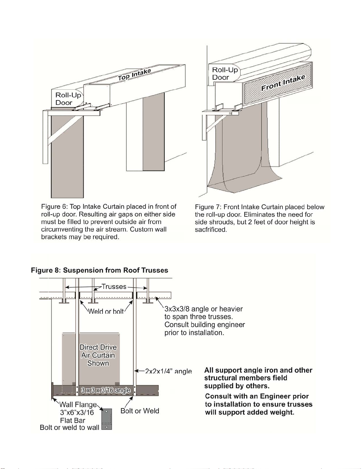
INSTALLATION AT ROLL-UP TYPE DOOR 11
SUSPENSION FROM ROOF TRUSSES 11
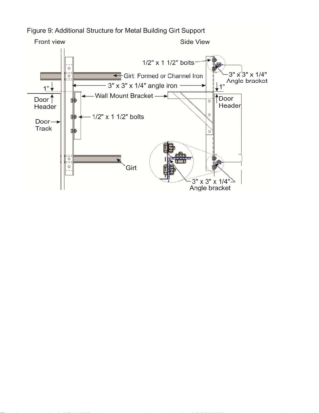
INSTALLATION ON METAL FRAME BUILDING GIRTS 12
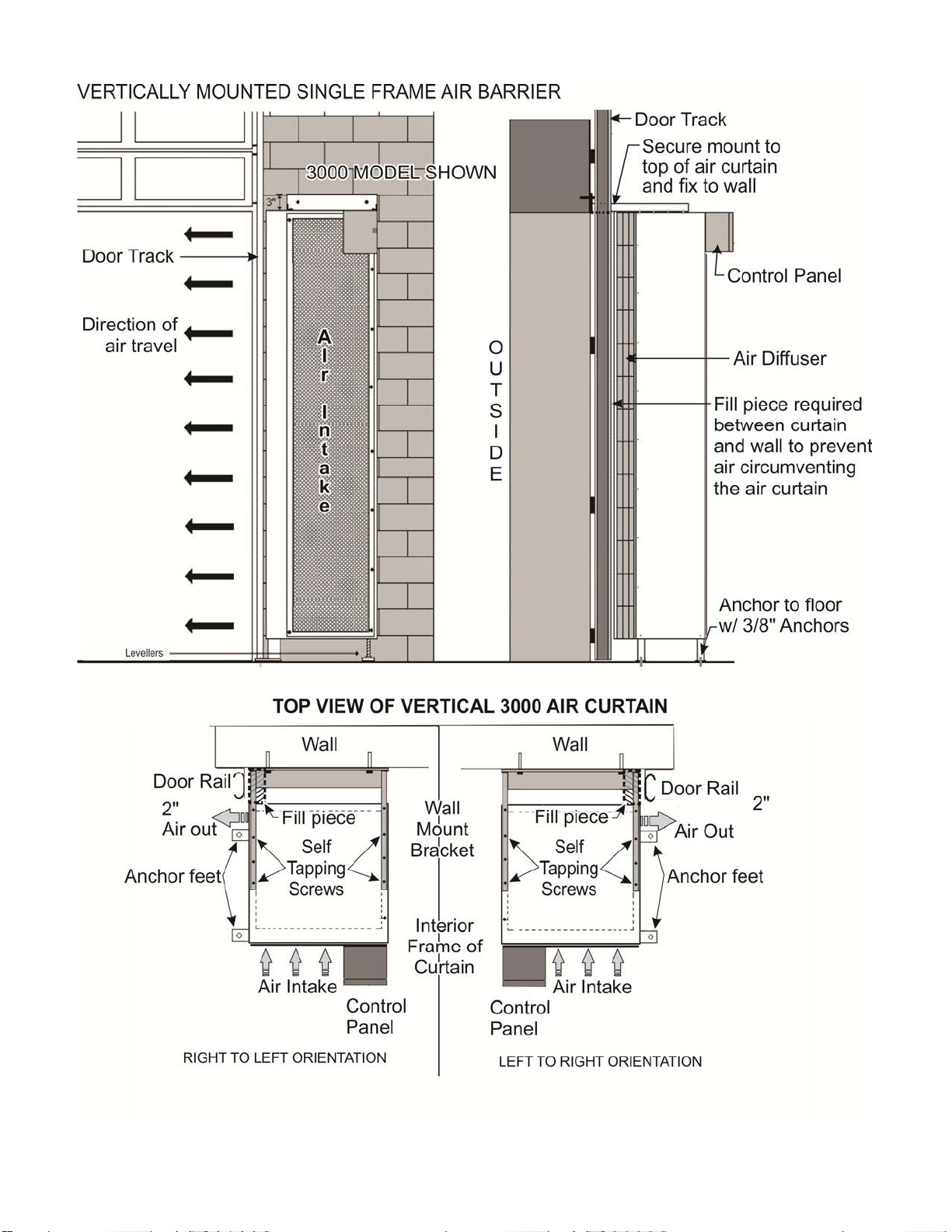
INSTALLATION OF VERTICAL MOUNT AIR CURTAIN 13
POSITIONING & SET UP OF PHOTO-ELECTRIC SENSOR 14
START UP PROCEDURE 15
DIFFUSER ADJUSTMENT / AIR SPLIT 15
MAINTENANCE 16
TROUBLESHOOTING GUIDE 16 - 17
MODEL 3000 SPECIFICATIONS 18 - 19
MAINTENANCE CHECKLIST 20
WARRANTY Back Page
IMPORTANT!!! Read and save these instructions.
Understand instructions thoroughly prior to beginning installation of your Air Curtain.
Placement of this equipment relative to the door is essential for proper function.
This product has no heat elements and uses waste heat of the facility to seal the opening.
INSTALLER TO PRESENT THIS MANUAL TO THE END USER, AND
AQUAINT END USER WITH REGULAR MAINTENANCE PROCEDURES

3
Air 3000 Series Manual
RL: 01A
APR 2016
SAFETY NOTICE!!! CAUTION!!!
Individual frames are very heavy and awkward. Use adequate means to handle.
Ensure all flange bolts are in place and tight prior to lifting Air Curtain.
Any and all lifting equipment should only be operated by qualified personnel.
Sliders and screens are in place prior to lifting.
Ensure Air Curtain is stable BEFORE beginning to lift. Secure it if necessary.
Do not walk under Air Curtain or allow others to do so while it is being lifting into position.
Overhead doors should be closed and power to them locked out during the installation.
Have at least two spotters on hand while lifting the Curtain to ensure a safe lift.
Remove or identify any and all obstructions/hazards prior to lifting the Curtain.
Lift on level ground only.
DO NOT install the Curtain on the outside of the building.
DO NOT install the Curtain on the dirty side of the environment.
DO NOT lift the Curtain into position from the opposite side of the door.
If the Air Curtain has been installed below the door header, have the door limited to open only to the
bottom of the Air Curtain.
Ensure structural integrity of wall/ceiling is adequate to support the weight of the Air Curtain.
SHOCK OR FIRE HAZARD: lock out power to Air Curtain and door before servicing.
Air Curtains are not designed or capable of replacing doors; they will only reduce the amount of air
infiltration while the door is open.
Ensure all protective guards and screens are in place prior to operating!
Rotating parts: keep hands and loose clothing clear while unit is operating.
INSPECTION UPON ARRIVAL
1. Inspect unit upon arrival. In the event damage has occurred: indicate on bill of lading; re-
port immediately to carrier; notify your supplier.
2. Confirm the unit(s) rating plate complies with the power supply at the site.
3. Confirm that the unit(s) supplied corresponds to the unit(s) ordered.
4. Confirm that controls supplied meet with unit ordered specifications and meet power supply
5. Report any deviations directly to your supplier.
HANDLING
1. To avoid damage prior to installation, leave the air Curtain packaged on its skid and/or in
its crate until the day of installation.
2. Store in a clean and DRY environment. Constructed with galvanized steel frames and gal-
vanized sheet metal covers, water stains may form if units are allowed to get wet.
3. Do not stack wrapped units!!!
4. Lift wrapped/crated units from the designated end only.
5. Fork extensions should be utilized on crates or pallets 8’ and longer.

4
Air 3000 Series Manual
RL: 01A
APR 2016
Savings and Comfort
Open doors account for a considerable amount of the energy loss in a building. A correctly in-
stalled Air Curtain can reduce the heat loss through a door as much as 90 %. An Air Curtain
greatly reduces exterior air infiltration and allows facilities to keep their doors open for extended
periods in winter time, creating a more comfortable work environment and saving a substantial
amount of energy. An Air Curtain can also prove to be beneficial to enhance manufacturing
processes where atmosphere and temperature are critical. In the summer time Air Curtains are
operated to keep out hot air/humidity, dust and insects, and retain conditioned air.
• A properly operated Air Curtain reduces energy cost by sealing door opening by up to 90%
• Maintain a more comfortable environment for employees (I.E. Service, Production & Ship-
ping/Receiving Areas).
• Keep out cold drafts, dust, fumes, insects & other contaminants.
• Reduce door cycles, wear & tear, and associated costs while providing clear unobstructed
doorways.
• Improve productivity by maintaining more consistent temperatures.
Proper Function of Air Curtain
The Air Curtain is activated by either a photo sensor switch (which immediately activates the
door curtain upon door opening) or an on/off switch. The Air Curtain should operate in conjunc-
tion with the opening of the door and should be in operation whenever there is a 10°F (6°C) dif-
ferential in external to internal temperature. For example in the spring/fall months the Air Cur-
tain is sometimes turned off due to indoor and outdoor temperatures being moderately similar.
In the event that the indoor and outdoor temperatures have a greater difference than 10°F (6°
C) the Air Curtain should operate to maximize the building efficiency. Air Curtain operation will
save energy costs for either heating or cooling.
• Air Curtain should be activated by either photo sensor switch or on/off switch.
• Air Curtain should be operated to seal off door opening from external temperatures, vehicle
fumes, insects and bugs, bird or dust infiltration.
• Air Curtain should be activated whenever the door is opened and the internal and external
temperatures vary by 10°F (6°C) .
• Never block the air intake to try to minimize the amount of air discharged.

5
Air 3000 Series Manual
RL: 01A
APR 2016
For the Model 3000, the Installer is responsible for the following:
• Direct Drive Units = SINGLE PHASE
• Confirm supply voltage in writing
• Install the Air Curtain in accordance with these installation instructions and any applicable
local / national codes
• Supply & Connect power line to Manufacturer supplied control panel on side of unit
• Affix and set up Manufacturer supplied photoelectric switch to door and connect wire from
control panel to switch (5’ of wire included)
• Confirm correct rotation of motor/s – Forward curved fans; rotation is from top intake down
to discharge nozzle
• Provide all necessary electrical requirements to meet local / national code
For this Air Curtain the end user is responsible for:
• Regular maintenance checks by a qualified maintenance technician
• Completion of Maintenance Checklist every 3 months
• See Checklist page 20
• Complete Air Curtain data at top of page (Date Installed; Model #; Serial #)
• Photocopy Checklist for maintenance file

6
Air 3000 Series Manual
RL: 01A
APR 2016
PRIOR TO INSTALLATION:
1. Confirm door dimensions
2. Determine style of overhead door; vertical lift, high lift, standard lift or low head room.
3. Confirm clearance. See manual for your appropriate door style and Air Curtain application.
4. Minimum clearance from top of door opening to underside of door hinge with the door com-
pletely open:
• Models 3000, 4000, 5000: 24” minimum clearance
• Models 6000, 7000: 28” minimum clearance
• See standard lift door with Air Curtain Figures 8 &10
5. If there is inadequate clearance, some of the door opening height will have to be sacrificed
or replace the standard lift door tracks with high or vertical lift tracks.
6. If the Air Curtain is installed 24” below door header, a dummy panel will have to be installed
to prevent short circuiting the Air Curtain system . See Standard Lift Door Installation
IMPORTANT!!!
TYPICAL FLANGING DETAIL FOR BOTH HORIZONTAL AND VERTICAL AIR CURTAINS
ENSURE ALL BOLTS ARE IN PLACE AND TIGHTENED BEFORE THE AIR CURTAIN IS
LIFTED INTO POSITION!!!
FLANGING DIAGRAM
Hardware supplied: Qty 8 x 1/2” x 1-1/2” bolts, nuts, washers, lock washers
Flange Spanner Plate: Qty 1 x 1/4” x 6” steel plate
Multiple frame DS Air Curtains are to be field wired while frames at floor level (Red to
Red / Black to Black).
Refer to electrical schematic located in the control panel.

7
Air 3000 Series Manual
RL: 01A
APR 2016

8
Air 3000 Series Manual
RL: 01A
APR 2016
INSTALLATION GUIDE
Horizontally Mounted Air Curtain: Mount to Solid Concrete Block or Precast Wall
1. Drill 3 x 5/8" diameter holes along centerline one side of each wall bracket. Measured from
top, the spacing of the holes should be approximately 2", 8" and 24" for the Model 3000,
4000, & 5000 wall mounts and 2", 8" and 30" for the Model 6000 & 7000 wall mounts. Hole
placement to align with wall component structural integrity. Figures 1 and 2 below illustrate
approximate locations for the holes.
2. To determine the mounting height of the wall brackets: Refer to Figure 3 (next page) for
standard lift door track, and Figure 4 for vertical / high-rise track. Note that for vertical / high
-rise track the mounting height of the wall bracket should be 1" above the door header.
3. Use the wall brackets to mark the hole spacing on the wall and proceed to drill 9/16" holes
through the wall. Locate bracket no more than 9" from the edge of the door (Figure 2).
4. Use 3" x 3/16" x sufficient length steel plates (field supplied by others) at the exterior of the
wall as backing to bolt the wall brackets in place (Figure 1).
5. Secure wall brackets with 1/2" threaded rod (Figure 1) with nuts and lock washers. Field
supplied by others.
6. Once both wall brackets are in place, place sliders in both ends of the air Curtain and set on
forklift.
7. Lift air Curtain up and above wall brackets. Center unit on door and lower onto brackets.
8. There should be 3" to 5" between wall and air Curtain for door clearance.
9. Confirm normal door operation before fixing sliders to wall brackets.
10.Through slider holes, drill 7/16" holes through the top of wall brackets and secure sliders in
place with the 3/8" hardware provided.
NOTE:
• Details for installation of wall mount brackets and air curtain sliders are on next pages
• Installation at roll-up doors is on page 9
• Overhead suspension from roof trusses is on page 9
• Installation to wall girts of metal frame building is on page 10

9
Air 3000 Series Manual
RL: 01A
APR 2016
Wall Mount Brackets

10
Air 3000 Series Manual
RL: 01A
APR 2016
• Air Curtain backwards
• Air Curtain too close to door
• Air Curtain too high above opening
Standard Lift Door: Bracket Mounting Height:
1. Raise door so a panel at turn in rail is at 45°
2. At end of door: measure 6.5” from wall to
interior surface of the angled door panel and
put a mark (see graphic below)
3. Measure height from floor to the mark
4. From the measured height:
- Deduct Air Curtain Height
- Deduct additional 2 inches
= Wall Bracket mounting height
11
Air 3000 Series Manual
RL: 01A
APR 2016
INSTALLATION AT ROLL-UP DOOR
12
Air 3000 Series Manual
RL: 01A
APR 2016
13
Air 3000 Series Manual
RL: 01A
APR 2016

14
Air 3000 Series Manual
RL: 01A
APR 2016
Positioning and Set-up of Photo-Electric Sensor Switch
Refer to detailed instruction sheet that accompanies the photo-electric sensor.
Ensure the sensor and the reflector are aligned and have a clear line of sight between .
A minimum separation of 3 inches is required between the sensor and the reflector.
15
Air 3000 Series Manual
RL: 01A
APR 2016
Model 3000 Startup Procedure
1. Keep by-standers clear of the Curtain for the initial start up
2. Confirm all covers and screens are in place
3. Keep the area free of loose articles
4. Turn power breakers and disconnect switches on
5. Turn power on to the Air Curtain
6. Open the door. Air Curtain activates
7. IMPORTANT: Adjust air diffuser and check air split at the floor (see below for procedure)
8. Secure air diffuser in its final position
9. Close door(s) ... Air Curtain deactivates
10.Check Troubleshooting Guide (next page) if any issues
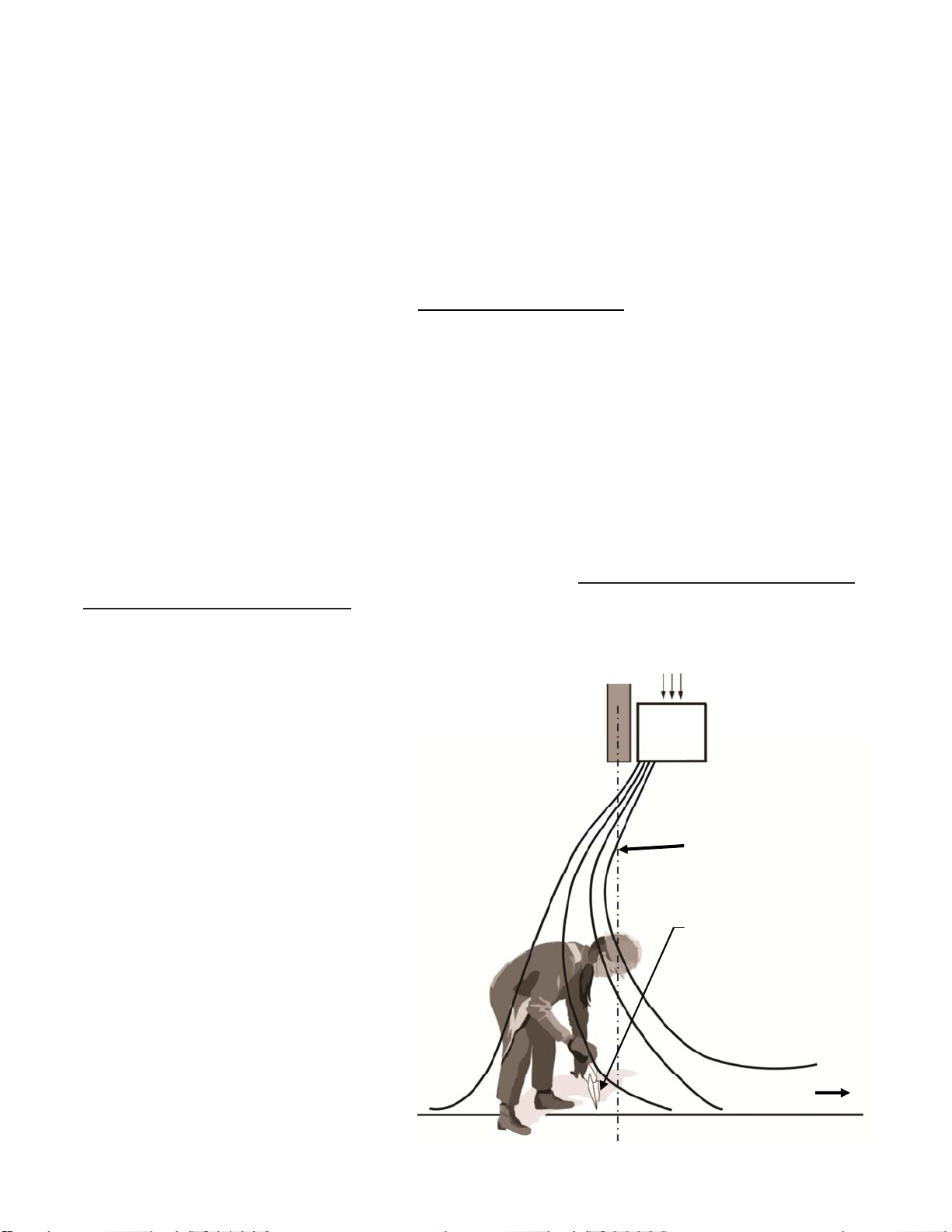
Initial Set Up: IMPORTANT
Set up of the Air Curtain is required after installation. In the event that conditions of the building
change or wind velocities differ from that of the initial air diffuser set-up, some future re-
adjustment may be required.
The Air Curtain should be set so that a small portion of the air stream is directed out of the door
opening, while the rest of the air blows back into the facility. Approximately 10-15 % of the air-
flow should be directed outdoors. This “loss” is necessary to prevent outdoor air infiltration near
the floor. This operation keeps outdoor air out, while the conditioned indoor air stays inside. Air
velocity by the floor should be approximately 800 ft/min (3-4 m/s).
Outdoors Indoors
Handerchief
/
tissue
straight down slightly
outside of doorway
centerline
800 ft/min
•Adjust air diffuser nozzle slightly
outwards approximately 10-15 degrees
•To find the airflow split location hold a
handkerchief, light cloth, or tissue by the
corner approximately 2-3 inches above the
floor and move it gently back and forth
across the doorway until it points straight
down
•The split location (cloth points straight
down) should be slightly outside the door-
way to overcome external wind conditions
trying to push the air stream inward
•Once split location has been determined
secure air diffuser nozzle adjustment bolts
to ensure stability of air flow
Centerline
of Doorway
16
Air 3000 Series Manual
RL: 01A
APR 2016
Maintenance Schedule - IMPORTANT
CAUTION! Shock and fire hazard. Lock out power before servicing. Maintenance
to be conducted only by qualified personnel working from a secure platform.
After the first month of operation, check the blower wheel for contamination, dirt build up, loose
motor mounting ring bolts, and blower set screws. Confirm that the blower wheel remains cen-
tered in the blower housing. Re-center if necessary.
Remove any foreign material that may be present, to prevent unbalancing and damaging the
blower wheel (this is particularly important with vertical Air Barriers). There are no grease fit-
tings for components in a Direct Drive Air Barrier.
Repeat the above check list after 6 months. Also visually inspect the rubber mounts on the mo-
tor mounting ring arms for wear. Replace rubber mounts if necessary.
Direct Drive Maintenance Checklist (every 3 months). If the environment is exceptionally
dirty inspect monthly. (see complete checklist page 20)
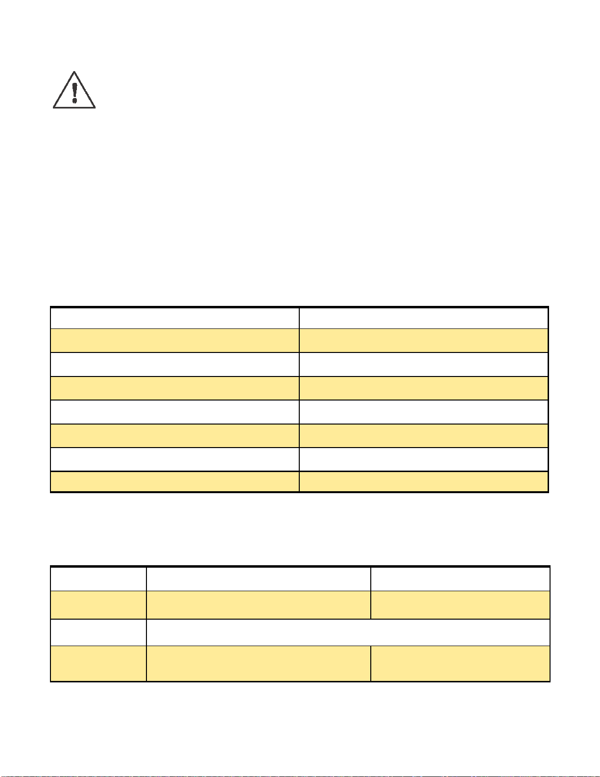
Trouble Shooting Guide
Symptom: Unit does not activate
INSPECTION REMEDY
Blower Wheel is Centered in its housing Re-center if necessary, tighten 204 lb⋅in
Foreign material in blower Remove foreign material
Excess buildup of dirt on blower wheel Blow the wheel clean with compressed air
Rubber pads on motor mounting ring arms Replace if excessively worn or missing
Motor Mounting bolts are tight & secure Tighten if necessary (snug tight only)
Correct Diffuser Position (see previous page) Air split should be slightly outside door frame
Intake Screen is free of debris Clear any debris
POSSIBLE CAUSE CHECK CORRECTIVE ACTION
No power to unit Breakers, control panel, switches Turn all appropriate switches on
No power to unit
Blown fuse Primary fuses in control panel or discon-
nect Replace as necessary
Confirm line voltage (by qualified electrician)

17
Air 3000 Series Manual
RL: 01A
APR 2016
Symptom: Power to unit, but will not start
Symptom: Little or no air flow
Symptom: Unit fails to deactivate
Symptom: Noisy Operation
POSSIBLE CAUSE CHECK CORRECTIVE ACTION
Transformer output Confirm transformer output voltage Check wiring; replace faulty
transformer
Photo Sensor Photo Sensor and wiring connections Replace if faulty
Incorrect voltage Line voltage Change motor
POSSIBLE CAUSE CHECK CORRECTIVE ACTION
Unit not turned On Switches, breaker, disconnect Turn switches to on position
Blowers plugged Blower fins Clean blowers
Filters plugged Filters Clean or replace
Air intake obstructed Intake screen, inside of cabinet Clear any obstruction
Air exhaust obstructed Air diffuser Clear any obstruction
POSSIBLE CAUSE CHECK CORRECTIVE ACTION
Photo sensor instal-
lation Photo sensor and reflector Realign photo sensor and reflector
Photo Sensor Photo sensor and reflector Remove obstruction, clean sensor &
reflector
Sensor sensitivity
set too low Open clear shield on sensor to
determine sensitivity level Turn dial under clear lid to a higher po-
sition until unit activates
Time delay set Photo Sensor Turn time delay dial to zero
POSSIBLE CAUSE CHECK CORRECTIVE ACTION
Scraping, grinding Sheared hub, bearings Replace defective component
Scraping, grinding Blower rubbing housing Reposition blower and tighten
Hum, vibration Motor, blower bolts, intake Tighten loose component
Hum, vibration Shaft straightness Replace bent section or complete shaft
High pitched whine Supply voltage vs. unit voltage Rewire or install correct motor
Rattle, scraping Foreign object blower, diffuser Remove foreign object
Chirping, squealing Belt tension, alignment Tension/align belts

18
Air 3000 Series Manual
RL: 01A
APR 2016
Torque Specs for all Direct Drive Air Barriers
Model 3000 Direct Drive Specifications
Component Bolt Size Torque Spec
Blower Set Screw 1/4" 204 lb⋅in
Motor Mount Bolts Grade 5* 1/4" Tighten to limiter
Frame Flange Grade 8* 1/2" 55 lb⋅ft
Slider Bolts Grade 5* 3/8" 20 lb⋅ft
Flange Spanner Plate Grade 8* 1/2" 55 lb⋅ft
* US Bolts
Head Marking Grade and
Material
Nominal Size
Range
(inches)
Mechanical Properties
Proof Load
(psi)
Min. Yield
Strength
(psi)
Min. Tensile
Strength
(psi)
3 Radial Lines
Grade 5
Medium Carbon Steel,
Quenched and Tempered 1/4 thru 1 85,000 92,000
6 Radial Lines
Grade 8
Medium Carbon Alloy Steel,
Quenched and Tempered 1/4 thru 1 120,000 130,000 150,000
120,000
Model Diffuser
Length
(in)
Weight
(Lbs ) HP
FLA
208/460/575
Volts Phase AVG dB CFM Maximum
Velocity
(FPM)
3006 72 300 3@1/2 10.5/4.0/3.6 1 70 8475 4500
3008 96 400 4@1/2 14/5.4/4.8 1 70 11300 4500
3010 120 500 5@1/2 17.5/6.75/6 1 70-71 14125 4500
3012 144 600 6@1/2 21/8.1/7.2 1 72-73 16950 4500
3014 168 700 7@1/2 24.5/9.45/8.4 1 73-74 19775 4500
3016 192 800 8@1/2 28/6.75/9.6 1 74-75 22600 4500

19
Air 3000 Series Manual
RL: 01A
APR 2016

20
Air 3000 Series Manual
RL: 01A
APR 2016
Maintenance Checklist: Every 3 months; Complete Curtain Data at top & Photocopy for file
Date Curtain Installed:
Curtain Model #: Serial #:
Maintenance P F
Check Control Panel
Center Blowers
Clean Blowers
Grease Bearings
Grease Motor(s)
Tension Belts
Confirm Alignment
Bearing Bolts Tight
Belt Guard in Place
Mounts Secure
Capacitors Tight and Work
Slider Bolts Secure
Clean Sensor Lenses
Clean Reflector
Reflector Secure
Intake Screen Clean /in Place
Check wall for Cracks
Insulation in Place
Noise/Vibration
Flange Bolts Tight
Filters Clean
Bollard Secure
Check Screws
Check Split (manual page 15)
Check Diffuser Louver Setting
Repair
Blower #
Bearing #
Motor #
Shaft
Mounts
Capacitor#
Bolts
Photo Reflector
Insulation
Control Panel
Belts
Pulleys
Belt Guard
Intake Screen
Diffuser
N
Y
Replace
Blower #
Motor(s) #
Capacitor #
Control Panel
Distribution Block
Photoelectric Sensor
Bearing #
Intake Screen
Motor Ring and Feet
Ground Lug
Contactor
Shaft
Pulleys
Bolts#
Diffuser
Diffuser Feet
Front Sheet Galv
Back Sheet Galv
Insulation
Wall Mount #
Slider #
Belts/Belt Guard
Bushing ‘Size’
End Cap L or R
Y
N
Door #:
Air Curtain #:
Checked by: Date:
Remarks:
P= Pass
F= Fail
Y= Yes
N= No
Table of contents
Other infrasave Heater manuals


Popular Heater manuals by other brands


EINHELL
EINHELL PS 12 operating instructions

EDM Product
EDM Product 07125 instruction manual

Heylo
Heylo KS 85 T Translation of the original instruction manual

iGenix
iGenix IG9509 user manual

cecotec
cecotec Ready Warm 9700 Dual Force instruction manual

Xvent
Xvent Breeze BR-15 Operating and installation instructions


