Nederlands
terugdrukken zodanig dat het pijpeinde gelijk ligt met de
omgezette rand van de montageplaat.
Plaats vanaf de buitenzijde het muurrooster met de daar-
aan gemonteerde trekstangen in de inlaatpijp. De trek-
stangen iets naar buiten buigen zodat deze licht klemmen
in de inlaatpijp waardoor het rooster op z’n plaats blijft.
Het merkteken “Top” boven houden bij het plaatsen van
het muurrooster. Schuif de twee bevestigingsbeugels (5)
over de trekstangen (6) en zorg er daarbij voor dat de
bevestigingsbeugels om de omgehaalde rand van de mon-
tageplaat haken. Moeren aanbrengen op de trekstangen
en handvast aandraaien. De bevestigingsbeugels op de
horizontale hartlijn van de inlaatpijp plaatsen. Zie ook de
merktekens in de montageplaat.
De geveldoorvoer met telescopische inlaatpijp
Deze is geschikt voor wanddiktes van 250 - 440 mm zon-
der inkorten van de inlaatpijpdelen. Door de pijpdelen in
te korten is deze geveldoorvoer geschikt te maken voor
wanddiktes van 70 tot 250 mm. De uitlaatpijp dient op
lengte te worden gemaakt volgens onder standaard gevel-
doorvoer tabel. De aan het muurrooster gemonteerde
trekstangen kunnen na montage van de geveldoorvoer
worden ingekort.
Indien voor wanddiktes van 70 tot 250 mm de telescopi-
sche inlaatpijp wordt toegepast dienen beide pijpdelen te
worden ingekort n.l.:
• het inlaatpijpdeel aan de muurroosterzijde gelijk aan de
wanddikte
• het pijpdeel aan de toestelzijde op een lengte = de wand-
dikte - 20 mm.
LET OP: de pijpdelen niet afknippen aan de zijde waar
de bevestigingsbeugeltjes zijn aangebracht.
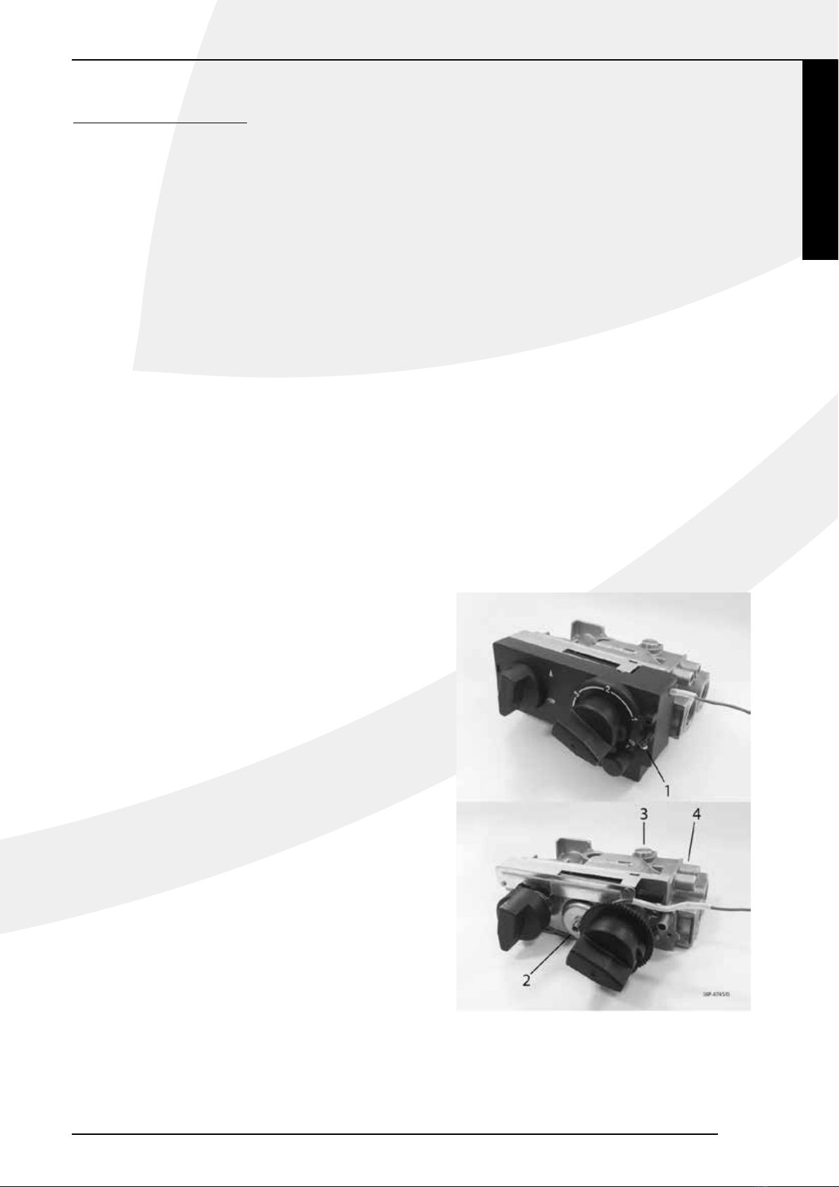
Installatie van de geveldoorvoer met telesco-
pische inlaatpijp (fig. 1, 3, blz. 57)
Breng het muurrooster met de daaraan gemonteerde
inlaatpijphelft van buitenaf in de gemaakte muuropening
met “Top” naar boven bij het plaatsen van het muur-
rooster. Schuif de andere helft van de inlaatpijp door de
montageplaat (2) en zorg daarbij dat de ingelaste beves-
tigingsbeugels (5) op de horizontale hartlijn liggen (zie
de merktekens in de montageplaat) en om de omgezette
montageplaatrand haken.
Breng de afdichtring (3) en de muurring (4) aan om de
inlaatpijp helft (Zie de figuur voor de juiste volgorde).
Neem het geheel en schuif de inlaatpijp helft van bin-
nenuit door de gemaakte muuropening in het reeds
aangebrachte inlaatpijp deel. Zorg daarbij dat de twee
trekstangen (6) door de bevestigingsbeugels (5) steken.
De montageplaat aandrukken tot tegen de wand. Breng
de moeren aan op de trekstangen (6) en zet deze tegen
de bevestigingsbeugels (5) handvast.
Bevestiging van de montageplaat
(fig. 1, 3, blz. 57)
Let op: stel de montageplaat (2) waterpas, zorg ervoor
dat de inlaatpijp naar buiten toe afloopt (1cm op 1 m)
en dat het muurrooster recht tegen de buitenmuur ligt.
Eventueel condenswater zal dan nooit in het toestel kun-
nen lopen.• Draai de moeren op de trekstangen vast.
• Zaag of knip de trekstangen af zodat deze niet buiten de
bevestigingsbeugels (5) uitsteken.
• Boor het gat voor de plug / keilmoer (7).
• Breng de plug / keilmoer aan in de muur.
• Bevestig de montageplaat m.b.v. de schroef / bout (8),
incl. sluitring (9).
Installatie aan een wand van brandbaar
materiaal (fig. 5, 7, blz. 58, 59)
Wanneer het toestel aan een wand van brandbaar
materiaal wordt geïnstalleerd dient de wanddoorvoer als
volgt te worden uitgevoerd.
• Maak ter plaatse van de doorvoering een vierkante open-
ing in de wand (maat M).
• Bij samendrukbare wanden de ruimte rondom goed
opvullen zodat de wand niet kan worden ingedrukt.
• De bout / schroef (8) vervangen door b.v. een hout-
draadbout.
• Plaats aan de kamerzijde tussen de montageplaat (2) en
de wand stralingsplaat 14.
• Bevestig aan de buitenzijde van de wand m.b.v.
4 schroeven (16) siluminplaat 15.
De stralingsplaat 14 en siluminplaat 15 zijn samen verpakt
en te bestellen bij uw leverancier. De montage van de
muurdoorvoer is verder zoals hiervoor beschreven.
N.B. Voor de berekening van de lengte van de in- en uit-
laatpijp dient ook de dikte van siluminplaat 15 te worden
meegeteld.
Installatie van het binnenwerk
(fig. 2, 4, blz. 57)
Neem het binnenwerk en zet deze met de onderrand op
de twee steunen van de montageplaat. Houd het binnen-
werk in evenwicht en schuif de uitlaatpijp een klein stukje
in de uitlaatopening van het binnenwerk ter ondersteu-
ning. Schuif nu het binnenwerk tegen de montageplaat en
zorg er daarbij voor dat de omgezette montageplaatrand
in de inlaatbus op de achterzijde van het binnenwerk valt
en de bouten (10) door de beugels (11) steken. Moeren
en sluitringen op de bouten (10) aanbrengen en vast
aandraaien tot tegen de aanslag. Daarna de draadstang
(12) in de beugel (13) schuiven. Moer met sluitring op de
draadstang (12) aanbrengen en aandraaien tot het binnen-
werk parallel met de wand staat.
N.B. Wanneer gemakkelijk toegankelijk, b.v. op de
begane grond, kan de uitlaatpijp ook van buitenaf worden
aangebracht nadat de roosterbinnenplaat en de korf zijn
gedemonteerd.
Bij de STYLE 4-01 en 5-01 moet na de montage van het
INSTALLATIE VOORSCHRIFT
3
STYLE