Ingco COS35568 User manual

EN
Cut Off Saw
COS35568 UCOS35568
COS35568-6 COS35568-8 COS35568-9
ingcoglobal
INGCO GLOBAL

2|English
Technical Specifications:
Model
COS35568
COS35568-6 COS35568-8 COS35568-9
UCOS35568
Input power:
2400W
2400W
Rated voltage:
220V-240V~50/60Hz
110V-120V~60Hz
Blade size:
355x25.4x3mm
14 x1 x1/8
No-load speed:
3900/min
3900/min
Max. cutting capacity:
in round pipe:
100mm
4
in square steel:
100X100mm
4 X4
in
:
120X100mm
4-3/4 X4
Max. cutting steel bar:
50mm
2
Specific Safety
Warnings
a)
Secure the workpiece. A workpiece clamped with clamping devices or in a vice is held more secure than by
hand.
b)
Do not work materials containing asbestos. Asbestos is consideredcarcinogenic.
c)
Take protective measures when dust can develop during working that is harmful to one’s health,
combustible or explosive.
Example: Some dusts are regarded as carcinogenic. Wear a dust mask and work with dust/chip extraction
when connectable.
d)
Keep your workplace clean. Blends of materials are particularly dangerous. Dust from light alloys can burn or
explode.
e)
Never leave the power tool before it has come to a complete stop. Cutting tools that are still running can
cause injuries.
f)
Do not use the power tool with a damaged cord. Do not touch the damaged cord and pull the plug from the
outlet when the cord is damaged
while working. Damaged cords increase the risk of an electric shock
g)
Connect power tools that are used in the open via a ground fault circuit interrupter.
h)
Never stand on the power tool. Serious injuries could occur when the power tool tips over or when
accidentally coming into contact with the cutting disc.
i)
Use the power tool only for dry cutting. Water penetrating into a power tool increases the risk of an electric
shock.
j)
Keep hands away from the cutting area while the machine is running. Danger of injury when coming into
contact with the cutting disc.
k)
Never remove cutting remainders, metal chips, etc. from the cutting area while the machine is running.
Always guide the tool arm back to the neutral position first and then switch the machine off.
l)
Guide the cutting disc against the workpiece only when the machine is switched on. Otherwise, there is
danger of kickback, when the cutting disc becomes wedged in theworkpiece.
m)
Operate the power tool only when the work area to the workpiece is clear of any adjusting tools, metal
chips, etc. Small pieces of metal or other objects that come in contact with the rotating cutting disc can strike the
operator with high speed.
n)
Always firmly clamp the workpiece. Do not cut workpieces that are too small to clamp. Otherwise, the
clearance of your hand to the rotating cutting disc is too small.
o)
Pay attention that persons are not put in danger by sparking. Remove any combustible materials in the
vicinity. Sparks develop when cutting metal.
p)
Use the cut off grinder only for cutting materials mentioned under “Intended Use”. Otherwise, the cut off
grinder can be subject to overload.

3|English
q)
Do not use damaged, out-of-center or vibrating cutting discs. Damaged cutting discs cause increased
friction, binding of the cutting disc and kickback.
r)
Always use cutting discs with correct size and shape (diamond versus round) of arbor holes. Cutting
discs that do not match the mounting hardware of the cut off grinder will run eccentrically, causing loss of
control.
s)
Do not touch the cutting disc after working before it has cooled. The cutting disc becomes very hot while
working.
Safety Warnings for Cut Off Saws with Retracting Blade Guard
Make sure that the blade guard operates properly and can move freely. Never clamp the blade guard in
place while retracted.
Specific safety rules
a)
Maintain labels and nameplates on the Cut-Off Saw. These carry important information. If unreadable or
missing, contact our company for a replacement.
b)
Keep hands and fingers away from cutting area and Grind Wheel. Keep one hand on the handle and
your second hand on the motor housing. If both hands are holding the saw, your hands and fingers cannot
be cut by the Grind Wheel.
c)
Do not reach under the Base of the Cut-Off Saw. The Upper Guard can not protect you from the Grind
Wheel below the base.
d)
Check Upper Guard for proper closing before each use. Do not operate the Saw if the Upper Guard
does not move freely and close instantly. Never clamp or tie the Upper Guard into the open position. If
the Saw is accidentally dropped, the Upper Guard may be bent. Raise the Upper Guard and make sure it
moves freely and does not touch the Grind Wheel or any other part, in all depths of cut.
e)
The Upper Guard should be retracted manually only for special cuts such as "Pocket Cuts" and
"Compound Cuts". Raise the Swing Guard only enough to begin the cut. As soon as the Grind Wheel
enters the material, the Upper Guard must be released. For all other sawing, the Upper Guard should
allowed to operate automatically.
f)
The Saw is not to be used for any cutting operation in the locked down position. The Saw should be in
the locked down position only for carrying and storage.
g)
Always use Grind Wheels with a 355mm Diameter,25.4mm round arbor hole, and rated at a minimum of
3900/min. Grind Wheels that do not match the mounting hardware of the Saw or that are rated at less than
the saw’s maximum RPM may fly off the Saw or may run eccentrically , causing loss of control.
h)
Never use damaged or incorrect Grind Wheel washers or bolts. The Grind Wheel’s washers and bolt were
specially designed for your Saw, for optimum performance and safety of operation.
i)
Do not use the included Grind Wheel to cut aluminum, copper, brass, or other non-ferrous metals. The
included Grind Wheel is designed to cut only ferrous (iron containing) metals such as steel alloys and cast
iron. If using other Grind Wheels, only use them on materials that the manufacturer recommends.
j)
To avoid accidental injury, always wear heavy duty work gloves and work bib when changing a Grind
Wheel.
k)
Before using the Cut-Off Saw, make sure the Grind Wheel is properly mounted on the Saw Spindle.
Make sure the Grind Wheel is balanced, and is not cracked or bent.
l)
The Grind Wheel will become hot while cutting. Allow the Grind Wheel to completely cool before touching.
m)
Allow the Grind Wheel to spin up to full speed before feeding it into the workpiece, When turning off the
Saw, allow the Grind Wheel to spin down and stop on its own. Do not press against the Grind Wheel to stop it.
n)
Do not force the Grind Wheel into the workpiece when cutting. Apply moderate pressure, allowing the
Grind Wheel to cut without being forced.
o)
Always turn off the Cut-Off Saw and unplug the Cord from its electrical outlet before changing
accessories or performing any inspection, maintenance, or cleaningprocedures.
p)
Use the right tool or attachment for the right job. Do not attempt to force a small tool or attachment to do
the work of a larger industrial tool or attachment. There are certain applications for which this product was

4|English
Upper Guard
Stopper Knob
Knurled Screw
designed. It will do the job better and more safely at the rate for which it was intended. Do not modity this
product, and do not use this product for a purpose for which it was not intended.
People with pacemakers should consult their physician(s) before using this product. Operation of
electrical equipment in close proximity to a heart pacemaker could cause interference or failure of the
pacemaker.
The warnings, precautions, and instructions discussed in this manual cannot cover all possible
conditions and situations that may occur. The operator must understand that common sense and caution are
factors which cannot be built into this product, but must be supplied by the operator.
For additional references to the parts listed in the following pages, refer to the
Prior to performing any assembly procedures, make sure the Cord of the Cut-Off Saw is unplugged
from its electrical outlet. Also, make sure the Cut-Off Wheel has completely cooled and wear work gloves
while replacing the Wheel.
Place the Cut-Off Saw in its fully raised position. To do so, turn the Stopper knob lock wise while pushing down
on the Handle.
Unscrew and remove the Knurled Screw.
Remove the Upper Guard. Then, set the Upper Guard aside, making sure not to allow it to be bent or damaged;
that can interfere with proper guard operation.
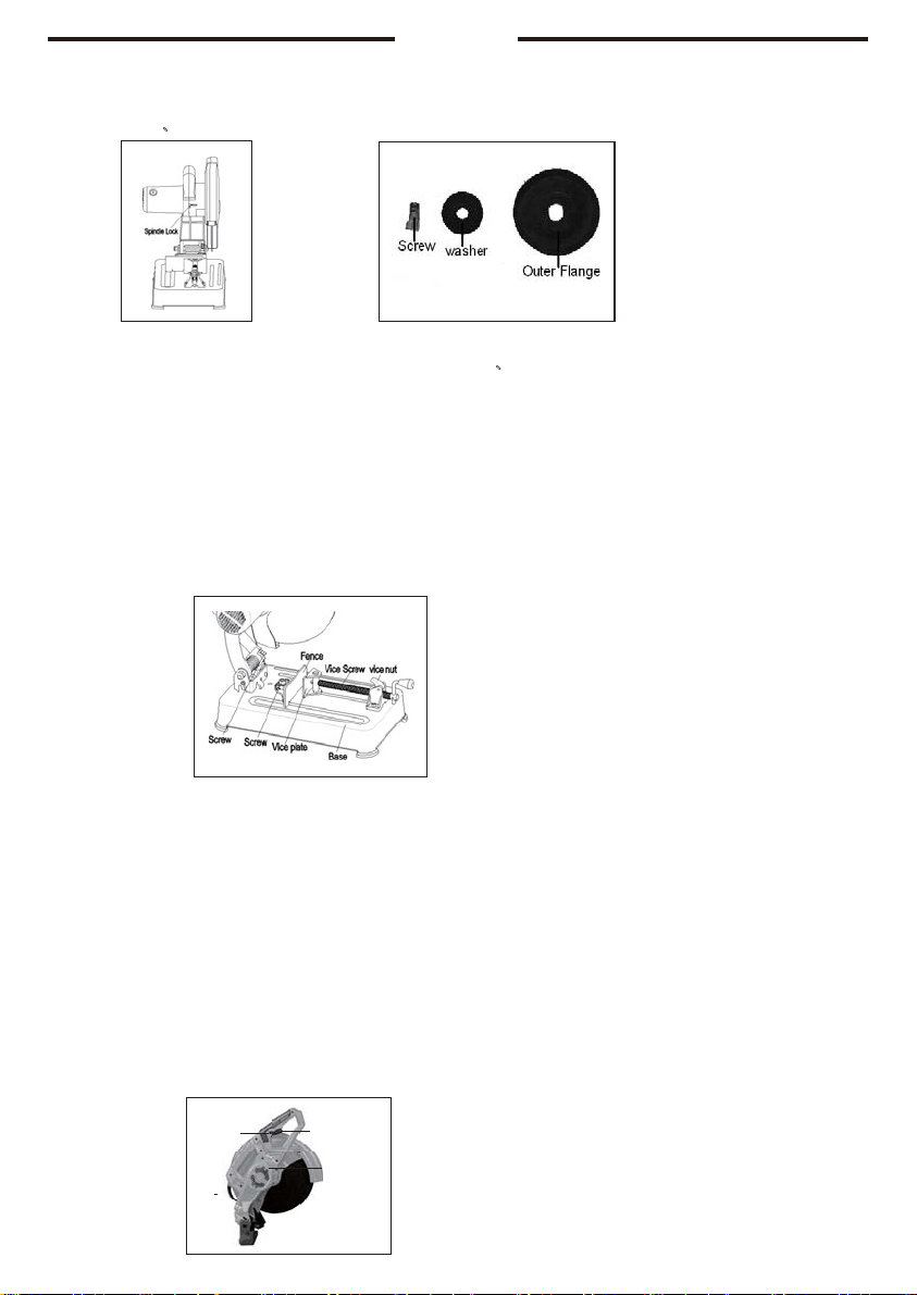
To keep the Grind Wheel from turning: Depress the Spindle Lock and turn the Grind Wheel until the Spindle
Lock clicks into place.
Use the Spanner to remove the Screw. NOTE: Make sure to turn the Screw counterclockwise to remove.
Remove the washer. Then, remove the Outer Flange.
Remove the old Grind Wheel, and replace it with a new Grind Wheel.
Grind Wheels that do not match the mounting hardware of the Saw
that are rated at less than the saw’s maximum RPM may fly off the Saw or may run eccentrically,
causing loss of control.
5|English
9.
Reinstall the Outer Flange (with the concave side facing the Wheel), washer, andScrew.
NOTE: Make sure to firmly tighten the Screw in al clockwise direction while depressing the Spindle Lock. (See
Figures G 、H)
Figure F Figure H
10.
Reinstall the Upper Guard, and secure it in place with the Knurled Screw. Make sure to tighten the Screw in
thescre w holereferredto inFigure D.(SeeFiguresD
The quick lock vise:
E、)
1.
The Quick Lock Vise allows for the angle of cut to be adjusted from 0 to 45 degrees to the left and 0 to 30
degrees to the right. To adjust the angle of cut, loosen the two Screws. Move the Fence to the desired angle as
indicated by the line on the Base of the Cut-Off Saw. Then, retighten the two Screws. ( See Figure I )
2.
The Quick Lock Vise features a vice nut which slows the operator to quickly release from the Vise the
workpiece being cut. To use the vice nut, pull the lever rearward to disengage the threads. Slide the clamp
forward until it contacts the workpiece. Lower the release lever, then tighten by turning the handle clockwise. To
remove the workpiece, loosen the Vice Screw slightly. Raise the vice nut and pull back on the Vice Screw. ( See
Figure I )
Figure I
To adjust the depth of cut:
The depth of cut may be adjusted, using the Screw. To cut shallower: Turn the Screw counterclockwise. Then,
tighten the Hex Nut. To cut deeper: Loosen the Hex Nut and turn the Screw clockwise. Then, tighten the Hex
Nut. (See FigureI)
To operate the Cut-Off Saw:
1.
To operate the Cut-Off Saw, first make sure the Cutting Arm is in it's the upright position with the Stopper knob
disengaged. (See Figure D)
2.
If necessary, adjust the angle of cut. Then, secure the workpiece in the vice nut. (See Figure I)
3.
Plug the Cord into the nearest 230 volt, grounded, electrical outlet .
Operation of Switch (see Figure J)
Start: press down the switch .
Keep running: press down the switch then depress the Switch button with your thumb. Stop: press down the
switch . Then, release the Switch..
Figure J
Brush Holder Cap
Carbon Brush
Brush holder
Cord
Switch
Switch button

6|English
4.
Allow the Grind Wheel to spin up to full speed. Then, slowly lower the Grind Wheel into the workpiece. (See
Figure D, and J )
5.
If the Grind Wheel does not pass completely through the workpiece, Raise the Saw Arm, turn off and unplug
the Saw, and wait until it comes to a complete stop. Remove stock being cut. Then, lower the Grind Wheel,
following the instructions on page10. (See Figure I)
6.
After adjusting the Screw (44), press down on the Cut-Off Saw and make sure the Grind Wheel does not
contact the bottom of the Base or any other part of the Base. (See Figure I)
7.
If the Grind Wheel touches the Base or any other part of the Base, raise the Grind Wheel until it clears,
following the instructions on page 7. (See Figure I)
8.
Plug the Cut-Off Saw back into its electrical outlet, and finish making the cut following Steps #3 and #4 above.
9.
Once the cut is completed, turn off the Cut-Off Saw by releasing the Switch. This allows the Switch button to
return to the “OFF” position. ( See Figure J )
10.
Unplug the Cut-Off Saw from its electrical outlet, and make sure to wait until the Saw has come to a complete
stop before removing the workpiece.
11.
Lock down the Saw with Stopper knob and store the Saw in a dry, safelocation.
Inspection, maintenance and cleaning
1. WARNING
!
Always
make
sure
the
Switch
is
in
its
“OFF”
position,
and
unplug
the
Cord
from
its
230
volt
electrical outlet before performing any inspection, adjustments, maintenance, or cleaning.
2.
Before each use, inspect the general condition of the Cut-Off Saw. Check for loose screws, misalignment or
binding of moving parts, cracked or broken parts, damaged electrical wiring, loose, cracked, or bent Grind
Wheel, and any other condition that may affect its safe operation. If abnormal noise or vibration occurs, have
the problem corrected before further use. Do not use damaged equipment.
3.
Daily: With a soft brush, cloth, or vacuum, remove all dust and debris from the Cut-Off Saw. Then, use a
premium quality, lightweight machine oil to lubricate all moving parts, except the Grind Wheel itself.
4.
To replace the Motor Carbon Brushes: It may become necessary at sometime to replace the two Carbon
Brushes when the Motor performance decreases, or stops working completely. The Carbon Brushes are
located on each side of the Housing. To do so, use a standard screwdriver (not included) to remove the two
Brush holder Caps. Then, remove the two Carbon Brushes from the Brush holders. If the Carbon Brushes are
worn down more than 1/2 of the original size, replace both Carbon Brushes. If however, the Carbon Brushes
are just dirty they may be cleaned by rubbing them with a pencil eraser. When installing the Carbon Brushes,
make sure the carbon portion of the Carbon Brushes contact the Motor Armature, and that the springs face
away from the Motor. Also, make sure the springs operate freely. After cleaning or replacement, replace the
Carbon Brush Caps with a screwdriver and tighten firmly.
NOTE: New Carbon Brushes tend to arc or spark when first used until
They wear and conform to the Motor's Armature. ( See Figure J )
Please read the following carefully
The manufacturer and/or distributor has provided the parts list and assembly diagram in this manual as a
reference tool only. Neither the manufacturer or distributor makes any representation or warranty of any kind to
the buyer that he or she is qualified to make any repairs to the product, or that he or she is qualified to replace any
parts of the product. In fact, the manufacturer and/or distributor expressly states that all repairs and parts
replacements should be undertaken by certified and licensed technicians, and not by the buyer. The buyer
assumes all risk and liability arising out of his or her repairs to the original product or replacement parts thereto, or
arising out of his or her installation of replacement parts thereto.
Symbols
he rating plate on your tool may show symbols. These represent important information about the product or
instructions on its use.

7|English
Wear hearing protection. Double insulated for
additional protection
Wear eye protection. Read the instruction manual
Danger area! Keep hands, fingers or arms
away from this area.
Environmental Protection and Guarantee
ENVIRONMENT PROTECTION
Waste electrical products should not be disposed of with household waste. Please recycle where
facilities exist. Check with your local Authority or retailer for recycling advice.

8|English
COS35568,UCOS35568,COS35568-6,COS35568-8,COS35568-9
83
82
84
85

9|English
COS35568,UCOS35568,COS35568-6,COS35568-8,COS35568-9
NO.
Part Description
Qty
NO.
Part Description
Qty
1
Brush cover
2
44
square key
1
2
Carbon brush
2
45
Bearing(6204-2z)
1
3
Brush hold
2
46
Hex nut
4
4
Pan head screw
4
47
Fixed guard
1
5
Spring washer
4
48
Cover
1
6
Flat washer
4
49
Gear
1
7
Motor housing
1
50
Bearing(6000-2z)
1
8
Stator
1
51
external criclips
1
9
plain washer
2
52
Hollow shaft
1
10 Spring washer
2
53
Hex nut
1
11 Screw
2
54
Screw
1
12 Bearing sleeve
1
55
Torsion spring
1
13 Bearing(6000-2z)
1
56
Dust cover
1
14 Washer
1
57
Flat washer
1
15 Armature
1
58
Spring washer
1
16 Bearing(6202-2RS)
1
59 Screw
1
17 Baffle
1
60 Screw
2
18 Pin
1
61 Spring washer
2
19 Rubber pin
1
62 Flat washer
2
20 Screw
8
63 Vice B
1
21 Right handle
1
64 Base
1
22 Screw
1
65 Flat washer
2
23 Switch
1
66 Pin
1
24 Cable 2*1.5 2m
1
67 Spring round pin
1
25 sheath
1
68 Vice nut
1
26 Screw
2
69 Pin
1
27 tension disc
1
70 Support bracke
1
28 Left handle
1
71 Screw rod
1
29 Hex nut
1
72 Screw rod handle
1
30 Screw
1
73 Handle sleeve
1
31 Cutting arm
1
74 Washer
1
32 Screw
1
75 Spring retainer
1
33 Lock pin
1
76 Screw
2
34 Spring
1
77 Spring washer
2
35 round-headed screw
2
78 Vice A
1
36
rubber rails
3
79 Flat washer
1
37
satfey guard
1
80 Hex nut
1
38 Hex nut
1
81 shock absorbing foot cover
4
39
Clamp sheet
1
82 six angle locknut
2
40
Outer flange
1
83 bracket O washer
1
41 Cutting wheel
1
84 wrench
1
42
Inner flange
1
85 non-slip mat
1
43
Spindle
1

This manual suits for next models
4
Table of contents
Other Ingco Saw manuals


