manuals.online logo
Brands
  1. Home
  2. •
  3. Brands
  4. •
  5. Ingersoll-Rand
  6. •
  7. Water Pump
  8. •
  9. Ingersoll-Rand ARA AF0475L Series User manual

Ingersoll-Rand ARA AF0475L Series User manual

Other Ingersoll-Rand Water Pump manuals

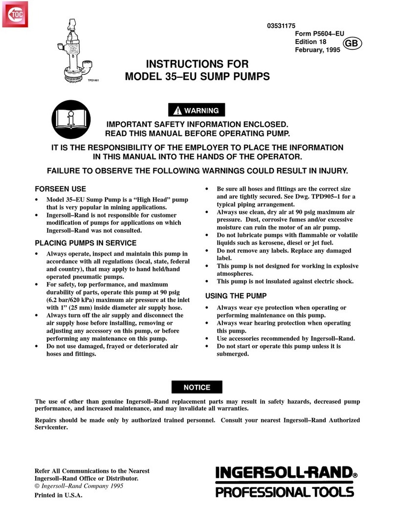
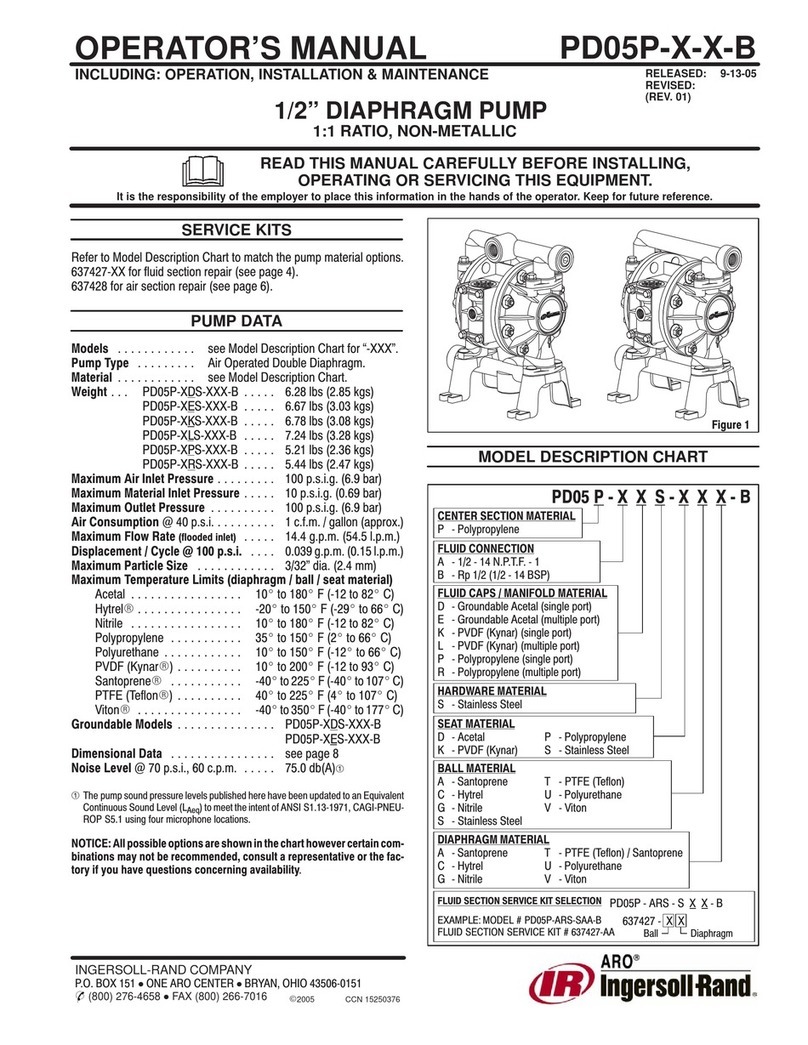
Ingersoll-Rand ARO PD07 Series User manual

Ingersoll-Rand

Ingersoll-Rand ARO PD07 Series User manual

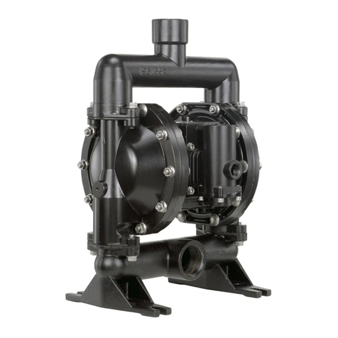
Ingersoll-Rand 6661HX-XXX-C User manual

Ingersoll-Rand

Ingersoll-Rand 6661HX-XXX-C User manual

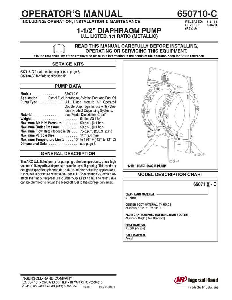
Ingersoll-Rand ARO PD30 C Series User manual

Ingersoll-Rand

Ingersoll-Rand ARO PD30 C Series User manual

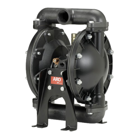
Ingersoll-Rand ARO 612729 User manual

Ingersoll-Rand

Ingersoll-Rand ARO 612729 User manual

Ingersoll-Rand 650883-XXX-B User manual

Ingersoll-Rand

Ingersoll-Rand 650883-XXX-B User manual

Ingersoll-Rand 251A1 User manual

Ingersoll-Rand

Ingersoll-Rand 251A1 User manual

Ingersoll-Rand 66243-X User manual

Ingersoll-Rand

Ingersoll-Rand 66243-X User manual

Ingersoll-Rand ARO PD20P Series User manual

Ingersoll-Rand

Ingersoll-Rand ARO PD20P Series User manual

Ingersoll-Rand ARO PD20 Series User manual

Ingersoll-Rand

Ingersoll-Rand ARO PD20 Series User manual

Ingersoll-Rand ARO PE03P A0S Series User manual

Ingersoll-Rand

Ingersoll-Rand ARO PE03P A0S Series User manual

Ingersoll-Rand ARO 670205-A User manual

Ingersoll-Rand

Ingersoll-Rand ARO 670205-A User manual

Ingersoll-Rand ARO PX01 Series User manual

Ingersoll-Rand

Ingersoll-Rand ARO PX01 Series User manual

Ingersoll-Rand ARO PD10E Series User manual

Ingersoll-Rand

Ingersoll-Rand ARO PD10E Series User manual

Ingersoll-Rand 67200 Series User manual

Ingersoll-Rand

Ingersoll-Rand 67200 Series User manual

Ingersoll-Rand ARO 66620 C Series User manual

Ingersoll-Rand

Ingersoll-Rand ARO 66620 C Series User manual

Ingersoll-Rand ARO 650239-X-B User manual

Ingersoll-Rand

Ingersoll-Rand ARO 650239-X-B User manual

Ingersoll-Rand ARO PW10A Series User manual

Ingersoll-Rand

Ingersoll-Rand ARO PW10A Series User manual

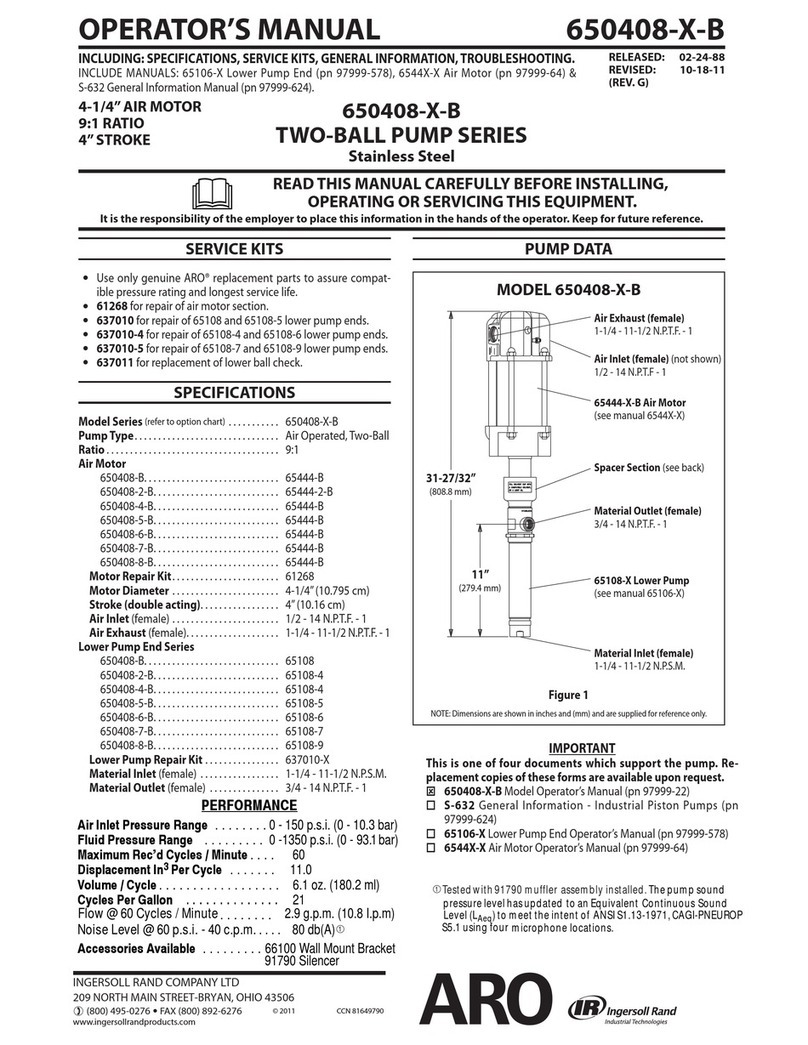
Ingersoll-Rand ARO 650408-X-B User manual

Ingersoll-Rand

Ingersoll-Rand ARO 650408-X-B User manual

Ingersoll-Rand ALBIN PUMP ALP User manual

Ingersoll-Rand

Ingersoll-Rand ALBIN PUMP ALP User manual

Ingersoll-Rand P237A1-EU Setup guide

Ingersoll-Rand

Ingersoll-Rand P237A1-EU Setup guide

Ingersoll-Rand ARO 612041 Series User manual

Ingersoll-Rand

Ingersoll-Rand ARO 612041 Series User manual

Ingersoll-Rand ARO PF20-B Series User manual

Ingersoll-Rand

Ingersoll-Rand ARO PF20-B Series User manual

Ingersoll-Rand ARO PM05R-B Series User manual

Ingersoll-Rand

Ingersoll-Rand ARO PM05R-B Series User manual

Ingersoll-Rand ARO 651729 User manual

Ingersoll-Rand

Ingersoll-Rand ARO 651729 User manual

Popular Water Pump manuals by other brands

Watershed Innovations HYDRAPUMP SMART FLEX Instructional manual

Watershed Innovations

Watershed Innovations HYDRAPUMP SMART FLEX Instructional manual

Graco Modu-Flo AL-5M instructions

Graco

Graco Modu-Flo AL-5M instructions

Messner MultiSystem MPF 3000 operating instructions

Messner

Messner MultiSystem MPF 3000 operating instructions

Xylem Bell & Gossett WEHT0311M Installation, operation and maintenance instructions

Xylem

Xylem Bell & Gossett WEHT0311M Installation, operation and maintenance instructions

WilTec 50739 Operation manual

WilTec

WilTec 50739 Operation manual

Franklin Electric Little Giant 555702 HRK-360S instruction sheet

Franklin Electric

Franklin Electric Little Giant 555702 HRK-360S instruction sheet

VS ZJ Series Operating	 instruction

VS

VS ZJ Series Operating instruction

Flotec FPZS50RP owner's manual

Flotec

Flotec FPZS50RP owner's manual

SKF Lincoln FlowMaster II User and maintenance instructions

SKF

SKF Lincoln FlowMaster II User and maintenance instructions

Xylem Lowara LSB Series Installation, operation and maintenance instructions

Xylem

Xylem Lowara LSB Series Installation, operation and maintenance instructions

Water Duro Pumps DCJ500 Operating & installation instructions

Water

Water Duro Pumps DCJ500 Operating & installation instructions

Action P490 Operating instructions & parts manual

Action

Action P490 Operating instructions & parts manual

Flo King Permacore Reusable Carbon Bag Disassembly. & Cleaning Instructions

Flo King

Flo King Permacore Reusable Carbon Bag Disassembly. & Cleaning Instructions

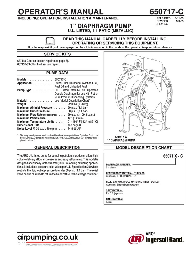
ARO ARO PD15P-X Operator's manual

ARO

ARO ARO PD15P-X Operator's manual

Pumptec 112V Series Operating instructions and parts manual

Pumptec

Pumptec 112V Series Operating instructions and parts manual

Virax 262070 user manual

Virax

Virax 262070 user manual

Neptun NPHW 5500 operating instructions

Neptun

Neptun NPHW 5500 operating instructions

Sensidyne Gilian BDX-II Operation & service manual

Sensidyne

Sensidyne Gilian BDX-II Operation & service manual

manuals.online logo
manuals.online logoBrands
  • About & Mission
  • Contact us
  • Privacy Policy
  • Terms and Conditions

Copyright 2025 Manuals.Online. All Rights Reserved.

INGERSOLL RAND COMPANY INC
209 NORTH MAIN STREET – BRYAN, OHIO 43506
(800) 495-0276 FAX (800) 892-6276 © 2020 CCN 47536825001
arozone.com
OPERATOR’S MANUAL & SALES AND ENGINEERING DATA
INCLUDING: OPERATION, INSTALLATION & MAINTENANCE
INCLUDE MANUAL: AF046X-XX AIR MOTOR (pn97999-1466) & S-632 GENERAL INFORMATION (pn97999-624)
RELEASED: 9-29-15
REVISED: 9-25-20
(REV: D)
AF0475LXXXXXX-XX-X
BASIC GREASE PUMP
READ THIS MANUAL CAREFULLY BEFORE INSTALLING,
OPERATING OR SERVICING THIS EQUIPMENT.
It is the responsibility of the employer to place this information in the hands of the operator. Keep for future reference.
4-1/4” AIR MOTOR
75:1 RATIO
0 - 7500 PSI RANGE
SERVICE KITS
yUse only genuine ARO® replacement parts to assure com-
patible pressure rating and longest service life.
y637512 for Lower Kit.
y637489 for air motor service only.
SPECIFICATIONS
Model Series ................... AF0475LXXXXXX-XX-X
Type ............................Air Operated Grease
Pump
Ratio .......................... 75:1
Air Motor Diameter ............. 4-1/4” (10.8 cm)
Stroke .................... 6” (15.2 cm)
Air lnlet ................... 1/2 - 14 NPTF
Material Outlet (female) .... 1/2 - 14 NPTF
Dimensional Data .............. see chart
PERFORMANCE
Air Inlet Pressure Range.........
30 - 100 psig (2 - 6.9 bar)
Fluid Pressure Range ........... 2250 - 7500 psig
(150 - 517 bar)
Max Rec’d Speed (Continuous). . . 75 cycles/min
Flowrate @ 75 cycles
per minute .....................
5.5 lbs/min (~0.73 gpm)
Displacement Per Cycle ......... 2.25 in
3
(36.87 cc)
Mount Accessories.............. 4148 Bung Adapter
AF0475LXXXXXX-XX-X
NOTE: Dimensions are shown in inches supplied for reference only.
MODELS
“A”
(for -1 model)
AF0475L4
42.894” 29.507” 16 Gallon (120 lbs)
“B” “Container Suitabilit
y”
AF0475L5
51.019” 37.632”
28.331”
“C”
36.456” 55 Gallon (400 lbs)
“A”
44.974” 29.507” 16 Gallon (120 lbs)
“B” “Container Suitability”
53.104” 37.632”
28.331”
“C”
36.456” 55 Gallon (400 lbs)
AF0475L4
AF0475L5
“B”
“C”
“A”
IMPORTANT
This is one of three documents which support the pump. Re-
placement copies of these forms are available upon request.
AF0475LXXXXXX-XX-X Model Operator’s Manual
(pn97999-1759).

AF046X-XX Air Motor Operator’s Manual (pn97999-1466).
S-632 General Information - Industrial Piston Pumps
(pn97999-624).
Air Inlet
1/2 - 14 NPT
Air Motor AF046X-XX
(see manual AF046X-XX)
Material Outlet
1/2 - 14 NPT
90142 Washer [C] 
90143 Spring [C] 
97459 Washer [C or SS]
91415 Packing (3x) [U]
Figure1
Page 2 of 4 AF0475LXXXXXX-XX-X
Item Description (size in inches) Qty Part No. [Mtl]
1 Connecting Rod
models AF0475L43PBL1-X (1) 97358-2 [C]
models AF0475L53PBL1-X (1) 97358-1 [C]
2Extension Tube
models AF0475L43PBL1-X (1) 97354-2 [C]
models AF0475L53PBL1-X (1) 97354-1 [C]
Piston & Tube Ass’y (includes 3-7) (1) 97365
3 Plunger (1) [C]
4Lower Tube (1) [C]
5 Ball Stop (1) [C]
6 Ball (9/32” dia.) (1) [C]
7 Primer Rod (1) [C]
8Primer Tube (1) 97357 [C]
9 Primer (1) 97373 [C]
10 Retaining Ring (1) 94397 [C]
11 Guide Washer (1) 97369 [Co]
12 Spacer Sleeve (1) 97372 [C]
13 Gasket (1) 97375 [Co]
14 Valve Seat (1) 97362 [C]
15 Truarc Ring (1) 76243-1 [C]
16 “U” Cup (1/8” x 13/16” o.d.) (1) Y186-54 [B]
17 Guide (1) 95132 [T]
18 Valve Body (1) 97363 [SH]
19 Gasket (1) 97460 [C]
Parts in Lower Repair Kit 637512
PARTS LIST / LOWER PUMP END
2
1
19
3
4
5
6
11
15
16
17
18
12
13
14
7
9
10
8
Torque Requirements
(1, 3 & 7) 50 - 60 ft lbs
(8) 340 - 360 ft lbs
Material Code
[B] =
Nitrile
[C]=
Carbon Steel
[Co] =
Copper
[SH]=
Hard Stainless Steel
[T]=
PTFE
[U] =
Polyurethane
[SS] =
Stainless Steel
Figure 2
TROUBLESHOOTING
No material at outlet. (Pump continuously cycles).
yEmpty material supply. Disconnect the air, replenish the
material supply.
yForeign matter is holding foot valve seats open in lower
pump tube assembly. Remove lower pump tube assem-
bly and clean valve seats.
Pump operates sluggishly, tends to stick when air is ap-
plied or control is opened.
yAir motor is dirty or lacks lubrication. Clean air motor.
yInsucient air pressure or volume of air. Check air sup-
ply.
Air bypasses through exhaust port.
yForeign matter is holding air valve open or lacks lubrica-
tion. Consult factory for nearest Service Center.
Motor stalls.
yForeign matter in pump, hose, control valve or spray tip
obstructing material ow. Check material supply hose
and control valve or tip.
yAir not getting to pump. Check air supply.
GENERAL DESCRIPTION
These ARO pumps are designed to handle heavy greases and
oils.
OPERATING AND SAFETY PRECAUTIONS
WARNING
EXCESSIVE INLET PRESSURE. Can cause
explosion resulting in severe injury or death. Do not
exceed maximum operating pressure of 7,500 psi (517
bar) at 100 psi (6.9 bar) inlet air pressure. Do not run
pump without using a regulator to limit air supply
pressure to the pump.
WARNING
EXCESSIVE MATERIAL PRESSURE. Can cause
equipment failure resulting in severe injury or prop-
erty damage. Do not exceed the maximum material
pressure of any component in the system.
PUMP RATIO X =MAXIMUM PUMP
INLET PRESSURE TO PUMP MOTOR FLUID PRESSURE
Pump ratio is an expression of the relationship between the pump
motor area and the lower pump end area. When 150 psi (10 bar) inlet
pressure is supplied to the motor of a 4:1 ratio pump it will develop a
maximum of 600 psi (41.4bar) uid pressure (at no ow) - as the uid
control is opened, the ow rate will increase as the motor cycle rate
increases to keep up with the demand.
NOTICE
Thermal expansion can occur when the uid in the ma-
terial lines is exposed to elevated temperatures. Example: Material lines
located in a non-insulated roof area can warm due to sunlight. Install a
pressure relief valve in the pumping system.
AF0475LXXXXXX-XX-X Page 3 of 4
PUMP DISASSEMBLY
NOTE: All threads are right hand. Disconnect air supply
and relieve all system pressure prior to servicing. Carefully
remove the parts, inspect for damage, nicks or excessive wear
and determine if any parts will need replacement.
1. Clamp (2) extension tube horizontally in a vise. Unthread
from air motor base. Take care to support motor weight
until the connecting rod is also disconnected.
2. Pull (1) connecting rod up until ats for 5/8” wrench are
exposed.
3. Use 5/8” wrench flats on each rod to unthread (1) con-
necting rod from the air motor rod.
4. Clamp (4) lower tube horizontally in a vise. Use a rod
or pipe to unthread and remove (8) primer tube. Allow
primer (9) to pull (12) spacer sleeve, (13) gasket and (14)
valve seat out of the (8) primer tube as it is being re-
moved.
5. Remove (10) retainer ring and unthread (9) primer from
(7) primer rod.
6. Remove (11-18) from (6) primer rod.
7. Remove (15) truarc ring, releasing (16) “U” cup. NOTE: Do
not remove (17) guide unless replacement is necessary.
8. With (4) lower tube still clamped horizontally in a vise,
unthread and remove (2) extension tube and (19) gasket.
9. Using a the 5/8” wrench ats on the (1) connecting rod
and the 3/4” wrench flats on the plunger (3), unthread
and remove the (1) connecting rod from the (3) plunger.
NOTE: Do not damage the o.d. of (3) plunger in any way.
10. Using a 5/32” diameter rod in the cross hole of (9) primer
rod and the 3/4” wrench ats on the plunger, unthread
and remove (9) primer rod, releasing (6) ball and (5) ball
stop.
PUMP REASSEMBLY
NOTE: Replace all soft parts with new ones included in
the repair kit. Refer to the illustration (Figure 2, page 2) for
“U” cup seal direction.
1. Assemble (5) ball stop and (6) ball into (3) plunger,
securing with (7) primer rod. NOTE 1: Torque (7) primer
rod to 50-60 ft lbs (67.8-81.3 Nm). NOTE 2: Items 3-7 are
not individually serviceable but must be replaced as an
assembly (97365).
2. Thread (1) connecting rod to (3) plunger, using 5/8” and
3/4” wrench ats respectively. NOTE: Tighten (1) con-
necting rod to 50-60 ft lbs (67.8-81.3 Nm).
3. Assemble (17) guide and (16) “U” cup into (18) valve
body, securing with (15) truarc ring. NOTE: Assemble
chamfered corner of (17) guide into (18) valve body rst.
4. Assemble (11) guide washer and (15-18) foot valve as-
sembly onto (7) primer rod.
5. Assemble (12) spacer sleeve, (13) gasket, and (14) valve
seat into (8) primer tube.
6. Thread (8) primer tube to (4) lower tube and hand
tighten.
7. Push piston assembly down as far as possible and thread
(9) primer onto (7) primer rod, securing with (10) retainer
ring.
8. Assemble (19) gasket and (2) extension tube to (4) lower
tube and hand tighten.
9. Ensure (91415) packings (3x), (90142) washer, (90143)
spring, and (90140) washer are secure inside of (AF0465)
air motor base.
10. Pull (1) connecting rod up until ats for 5/8” wrench are
exposed.
11. Using the 5/8” wrench ats on (1) connecting rod and
the air motor rod, thread and tighten. NOTE: Torque (1)
connecting rod to 50-60 ft lbs (67.8-81.3 Nm).
12. Assemble (2) extension tube to air motor base. Clamp
base horizontally in vise and tighten (8) primer tube to
340-360 ft lbs (461.0-488.1 Nm) in order to tighten tub-
ing components simultaneously.
DIMENSIONS
TOP VIEW
1/2 -14 NTPF-1
AIR INLET
61°
CENTERLINE OF
MATERIAL OUTLET
Page 4 of 4 AF0475LXXXXXX-XX-X
PN 97999-1759
PERFORMANCE CURVES
0153045607590105
0
10
20
30
40
50
60
70
80
0
1000
2000
3000
4000
5000
6000
7000
8000
012345678
Cycles Per Minute
AIR CONSUMPTION (SCFM)
BACK PRESSURE (PSI)
Pounds per Minute (Grease)
NLGI #1 Grease at Room Temperature
70 PSI
100 PSI
100 PSI
70 PSI
40 PSI
40 PSI
NOTE:NON SHADED AREA OF THE GRAPH REPRESENTS RECOMMENDED OPERATING RANGE FOR CONTINUOUS DUTY