manuals.online logo
Brands
  1. Home
  2. •
  3. Brands
  4. •
  5. Ingersoll-Rand
  6. •
  7. Water Pump
  8. •
  9. Ingersoll-Rand P237A1-EU Setup guide

Ingersoll-Rand P237A1-EU Setup guide

Form 16575458
Edition 1
July 2005
Sump Pumps
Model P237A1-EU and P237A3-EU
Maintenance Information
Save These Instructions
2Form 16575458-Edition 1
WARNING
Always wear eye protection when operating or performing maintenance on this pump.
Always turn off the air supply and disconnect the air supply hose before installing, removing or adjusting any accessory on this pump or before
performing any maintenance on this pump.
Lubrication
Each time a P237 Sump Pump is disassembled for maintenance and
repair or replacement of parts, lubricate the Pump as follows:
1. Remove the Oil Chamber Plug (8) and fill the oil chamber in the
Backhead (1) with Ingersoll-Rand No. 50 Oil.
2. Before attaching the air hose, inject about 3 cc of oil into the air inlet.
3. After each four hours of operation, unless an air line lubricator is
used, fill the oil chamber in the Backhead with oil.
4. After each forty hours of operation, or as experience indicates, pump
10 or 15 strokes of Ingersoll-Rand Water Pump Grease No. 80 into
the Grease Fitting (15) on the Motor Housing (14). Use the
No. P25-228 Grease Gun.
5. We recommend the use of Ingersoll-Rand No. 8LUB12 Lubricator
located in the air supply line as close to the Pump as practical. Keep
the Lubricator filled with Ingersoll-Rand No. 50 Oil.
Air Strainer
Periodically, clean the Air Strainer Screen (9) as follows:
1. Shut off the air supply to the Pump.
2. Unscrew the Air Strainer Plug (11).
3. If the Screen still appears clogged, unscrew the Air Strainer Cap (10)
and withdraw the Screen. Clean the Screen in a suitable cleaning
solution in a well ventilated area.
Disassembly
General Instructions
1. Do no disassembly the Pump any further than necessary to replace
or repair damaged parts.
2. Whenever grasping a part in a vise, always use leather-covered or
copper-covered vise jaws to protect the surface of the part and help
prevent distortion. This is particularly true of threaded members and
housings.
3. Do not remove any part which is a press fit it or on a subassembly
unless the removal of that part is necessary for repairs or replacement.
Disassemble a P237 Pump as follows:
1. If the Air Strainer Screen (9) is to be cleaned or replaced, unscrew
the Air Strainer Cap (10) and withdraw the Screen.
2. Unscrew and remove the Backhead Cap Screws (13). Lift off the
Backhead.
3. If the oiler is to be disassembled, remove the Oiler Body Retainer (7)
and withdraw the Oiler Body Assembly (2) from the Backhead.
4. Unscrew the Impeller Cover Cap Screws (48) and remove the Inlet
(46) and Impeller Cover (45).
5. Sprag the Impeller (41) against rotation by inserting a long
screwdriver through one of the suction ports and into the discharge
port in the Housing (14).
6. Unscrew the Impeller Retaining Screw (43) and remove the Impeller.
7. While grasping the Controller (18) in one hand, gently tap on the
impeller end of the Rotor Shaft (32) with a plastic hammer and
withdraw the motor from the Housing.
8. The upper Rotor Shaft Bearing (33) and Bearing Spacer (34) usually
come out with the motor. Slide them off the Rotor Shaft.
NOTICE
The Controller Retaining Nut (20) has a right-hand thread.
9. Grasp the Rotor Shaft vertically in copper-covered vise jaws, and
unscrew the Controller Retaining Nut.
NOTICE
The Controller Assembly has a left-hand thread.
10. Using the No. 99V60-950 Controller Wrench, unscrew the Controller
Assembly.
NOTICE
Do not attempt to disassemble the Controller. It is available only
as a unit.
11. Lift off the Rear End Plate Gasket (22).
12. Set the Bearing Cage (21) on blocks on an arbor press. Using a
metal sleeve that contacts only the outer race of the Rear Rotor
Bearing (19), press off the Bearing Cage.
13. If it is necessary to removethe Rear Rotor Bearing, insert the Rear Rotor
Bearing into the No. 99V60-A952 Bearing Clamp and tighten the nut on
the fixture. Insert the No. 99V60-951 Seal Pressing Tool in the center.
14. Lift off the Rotor Bearing Seal (19) and Rear End Plate (23).
15. Lift off the Cylinder (24).
16. Remove the Vanes (29).
17. Withdraw the Rotor (27) and lift out the Rotor Key (28).
18. Lift off the Front End Plate (30).
19. Remove the Motor Clamp Washers (31).
NOTICE
The Water Seal Cap Assembly (37) has a left-hand thread.
Do not remove the Water Seals (38) from within the Water Seal
Cap unless you have two new Seals on hand for installation.
The Water Seals are always damaged during the removal
process. Always check the Water Seals for wear or leakage.
20. Using a water seal cap spanner wrench, unscrew and remove the
Water Seal Cap Assembly.
21. Withdraw the Seal Spacer (35).
22. The Lower Shaft Bearing (33) can usually be pushed from the
Housing with a wooden dowel. However, if the Water Seals were
badly worn so that water got into and around the Bearing, it may be
necessary to forcibly drive the Bearing from the Housing. If this is the
case, make certain you have a new Bearing on hand for installation.
Assembly
General Instructions
1. Always press on the inner ring of a ball-type bearing when installing
the bearing on a shaft.
2. Always press on the outer ring of a ball-type bearing when pressing
the bearing in a bearing recess.
3. Whenever grasping a part in a vise, always use leather-covered or
copper-covered vise jaws. This is particularly true of threaded
members and housings.
4. Except for bearings, always clean every part, and wipe every part
with a thin film of oil before installation.
5. Check every bearing for roughness. If an open bearing must be
cleaned, wash it thoroughly in a clean solution and dry with a clean
cloth. Sealed or shielded bearings should not be cleaned.
6. Apply a film of O-ring lubricant to all O-rings before installation.
Assemble a P237 Pump as follows:
1. If the Water Seals (38) were removed from the Water Seal Cap (37),
install new Seals as follows:
a. Press the first Seal, lip side first, into the Water Seal Cap until it
bottoms against the shoulder.
b. Press the second Seal, lip side trailing, into the Water Seal Cap
until the trailing edge of the Seal is flush with the face of the Water
Seal Cap.
c. Insert the Impeller Spacer (39), beveled end first, through both
Seals until its beveled end is flush with the threaded end of the
Water Seal Cap.
2. Install the lower Shaft Bearing (33) followed by the Seal Spacer (35)
in the bottom of the Housing (14) until the Bearing seats against the
Housing Snap Ring (36).
CALL 1-800-577-8111 FOR SALES AND SUPPORT
CLICK HERE TO RETURN TO WEBSITE
Form 16575458-Edition 1 3
3. Using a water seal cap spanner wrench, install the Water Seal Cap
Assembly (37). Tighten the Water Seal Cap 20 to 25 ft-lb
(27 to 34 Nm) torque.
4. Grasp the large diameter end of the Rotor Shaft (32) in leather-covered
or copper-covered vise jaws so that the small diameter end is upward.
5. Slide the Front End Plate (30), bearing recess first, down over the
Rotor Shaft.
6. Place the Rotor Key (28) in the keyslot in the Rotor Shaft.
7. Slide the Rotor (27) down over the Rotor Shaft, engaging the Rotor Key.
8. Place a Vane (29) in each vane slot.
9. Place the Cylinder (24), small dowel first, down over the Rotor so that
the small dowel engages the alignment hole in the Front End Plate.
10. Place the Rear End Plate (23) over the Rotor Shaft and against the
Cylinder, so that it engages the Cylinder Dowel (26).
11. Check the outside diameter and large inside diameter of the Rotor
Bearing Seal (19) for wear. If the outside diameter of the hub is worn to
1.76" (29.881 mm) or smaller, and/or the large inside diameter is worn
to 0.910" (23.122 mm) or larger, install a new Rotor Bearing Seal.
NOTICE
Take all measurements 90° to the left of the dowel hole when
facing the hub side of the Seal.
Install the Rotor Bearing Seal (19), flat side first, so that the Cylinder
Dowel engages the alignment hole in Bearing Seal.
12. Press the Rear Rotor Bearing (19) onto the hub of the Controller (18).
13. Press the Controller Assembly into the hub side of the Rotor Bearing
Cage (21) until it is within 1/8" (3 mm) of seating.
NOTICE
The Rotor Shaft has a left-hand thread; turn counterclockwise to
install.
14. Using the No. 99V60-950 Controller Wrench, install the assembled
Controller, Bearing and Cage on the Rotor Shaft.
NOTICE
Tighten the Controller to 8 to 10 ft-lb (10.8 to 13.5 Nm) torque. Do
not exceed 10 ft-lb (13.5 Nm) torque. The Controller may be
damaged if this torque is exceeded.
NOTICE
The Controller Retaining Nut has a right-hand thread.
15. Install the Controller Retaining Nut (20). Tighten the Nut to 6 to 9 in-lb
(0.67 to 1.07 Nm) torque.
16. Remove the assembled motor from the vise.
17. Slide the upper Rotor Shaft Bearing (33) on the large diameter end of
the Rotor Shaft until it seats against the shoulder on the Shaft.
18. Slide the Bearing Spacer (34) on the Rotor Shaft until it contacts the
Bearing.
19. Stand the Housing (14) upright on the workbench.
20. Place the two Motor Clamp Washers (31), concave side first, in the
bottom of the housing bore, so that the outer rim of the leading
Washer contacts the Housing.
21. Install the assembled motor shaft end first into the Housing until the
Front end Plate seats against the Motor Clamp Washers.
22. Place the Rear End Plate Gasket (22) on the face of the Rear Rotor
Bearing Cage, aligning the dowel hole in the Gasket with the Cylinder
Dowel.
23. If the Oiler Body Assembly (2) was disassembled, install two new
Oiler Felts (4) in the Oiler Body, and retain them with the Oiler
Adjusting Screw (5). Run the Screw in until its trailing face is flush
with the face of the Oiler Body.
24. Install the Oiler Body O-Rings (3) and (6) in their respective grooves
on the Oiler Body.
25. Install the Oiler Body Assembly in the Backhead and retain it with the
Oiler Body Retainer (7).
26. Place the Housing Seal (17) on the rim of the Housing.
27. Place the Backhead (1) on the Housing, making certain the Cylinder
Dowel engages the dowel hole in the Backhead. Install the Backhead
Cap Screws (13) and Lock Washers (12). Tighten them to 20 ft-lb
(27 Nm) torque.
28. Lay the Pump on its side and slide the Impeller (41), hub side first, on
the splined end of the Rotor Shaft. Manually rotate the Impeller. If it rubs
against the Housing, install an Impeller Shim (40) or Shims as required
to provide running clearance between the Impeller and Housing.
29. Install the Impeller Retaining Washer (42) and Screw (43). Tighten the
Impeller Retaining Screw to 12 to 15 ft-lb (16.2 to 20.3 Nm) torque.
30. For the most efficient operation of the Pump, particularly against high
heads, it is necessary that the clearance between the Impeller and
Impeller Cover (45) be regulated at .010". Place the Impeller Cover
on the base of the Housing, using the required Impeller Cover
Shim (44) or Shims to obtain the desired clearance.
31. Place the Inlet (46) against the Impeller Cover and install the Impeller
Cover Cap Screws (48) and Lock Washers (47). Tighten the Cap
Screws to 9 to 12 ft-lb (12.2 to 16.2 Nm) torque.
32. Inject 10 or 15 strokes of Ingersoll-Rand No. 80 Water Pump
Grease into the Grease Fitting (15) on the Motor Housing (14). Use
the No. P25-228 Grease Gun.
Troubleshooting Guide
Related Documentation
For additional information refer to:
Sump Pumps Product Safety Information Manual Form 16576597,
Sump Pumps Product Information Manual Form 04585154,
Sump Pumps Parts List Manual Form 16574832.
Manuals can be downloaded from www.irtools.com
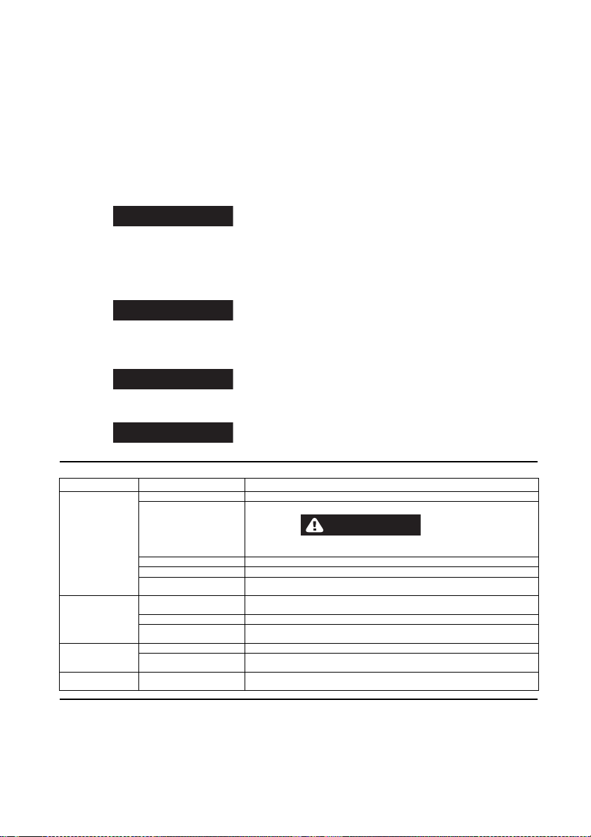
Trouble Probable Cause Solution
Low power or low free
speed Low air pressure at the Inlet Check the air pressure at the Inlet. The Pressure must not exceed 90 psig (6.2 bar/620 kPa).
Plugged InletBushingScreen or
Air Strainer Screen Clean the Screen in a clean, suitable, cleaning solution. If it cannot be cleaned, replace it.
WARNING
Never operate a Sump Pump without an Inlet Screen. Ingestion of dirt into the
Sump Pump can, in some cases, cause an unsafe condition.
Worn or broken Vanes Replace the complete set of Vanes.
Worn or broken Cylinder Replace the Cylinder if it is worn or broken or if the bore is scored or wavy.
Improper lubrication or dirt
build-up in the motor. Lubricate the Sump Pump as instructed in LUBRICATION. If lubrication does not result in
satisfactory operation, disassemble the motor inspect and clean all parts.
Rough operation Worn or broken Rear Rotor
Bearing or Front Rotor Bearing Examine each Bearing. Replace the Rear Rotor Bearing Seal Assembly if worn or damaged
or replace the Front Rotor Bearing.
Worn Rotor Key Replace the Key. Check the Arbor and Rotor for keyslot wear and replace if necessary.
Bent Arbor Mount the Arbor on centers. Check the bearing diameter runout with an indicator. Replace the
Arbor if runout exceeds .002" Total Indicator Reading.
Scoring of end Plates
or Cylinder Improper assembly Make certain that all motor parts are properly aligned prior to clamping the motor assembly.
Rotor Bearing Seal
misalignment Loosen the Cylinder Case Screws. Rotate the spindle by hand to align the seal. Re-tighten
the Screws to 14 ft-lb (19 Nm) torque. The Spindle must rotate freely.
High free speed Worn Rotor Bearing Seal Replace the Rotor Bearing Seal if the outside high diameter of the hub is worn to 1.76" or
smaller and/or the large inside diameter is worn 0.910" or larger.

This manual suits for next models

1

Other Ingersoll-Rand Water Pump manuals

Ingersoll-Rand ARO PP10A Series User manual

Ingersoll-Rand

Ingersoll-Rand ARO PP10A Series User manual

Ingersoll-Rand 670053 Series User manual

Ingersoll-Rand

Ingersoll-Rand 670053 Series User manual

Ingersoll-Rand 650484-X User manual

Ingersoll-Rand

Ingersoll-Rand 650484-X User manual

Ingersoll-Rand ARO PD07 Series User manual

Ingersoll-Rand

Ingersoll-Rand ARO PD07 Series User manual

Ingersoll-Rand 35-EU User manual

Ingersoll-Rand

Ingersoll-Rand 35-EU User manual

Ingersoll-Rand PD30*-*-B User manual

Ingersoll-Rand

Ingersoll-Rand PD30*-*-B User manual

Ingersoll-Rand ARO 650875-XX4-B Series User manual

Ingersoll-Rand

Ingersoll-Rand ARO 650875-XX4-B Series User manual

Ingersoll-Rand ARO EVO EP10 Series User manual

Ingersoll-Rand

Ingersoll-Rand ARO EVO EP10 Series User manual

Ingersoll-Rand 66615X-X-C User manual

Ingersoll-Rand

Ingersoll-Rand 66615X-X-C User manual

Ingersoll-Rand ARO PP10A A Series User manual

Ingersoll-Rand

Ingersoll-Rand ARO PP10A A Series User manual

Ingersoll-Rand ARO PM30R C Series User manual

Ingersoll-Rand

Ingersoll-Rand ARO PM30R C Series User manual

Ingersoll-Rand ARO WLM2203A 2 Series User manual

Ingersoll-Rand

Ingersoll-Rand ARO WLM2203A 2 Series User manual

Ingersoll-Rand LM2203A Series User manual

Ingersoll-Rand

Ingersoll-Rand LM2203A Series User manual

Ingersoll-Rand PD05P series User manual

Ingersoll-Rand

Ingersoll-Rand PD05P series User manual

Ingersoll-Rand MP PUMPS CHEMFLO 1 User manual

Ingersoll-Rand

Ingersoll-Rand MP PUMPS CHEMFLO 1 User manual

Ingersoll-Rand 6661HX-XXX-C User manual

Ingersoll-Rand

Ingersoll-Rand 6661HX-XXX-C User manual

Ingersoll-Rand ARO 650875 C Series User manual

Ingersoll-Rand

Ingersoll-Rand ARO 650875 C Series User manual

Ingersoll-Rand ARO NP322L01-1 User manual

Ingersoll-Rand

Ingersoll-Rand ARO NP322L01-1 User manual

Ingersoll-Rand ARO EVO EP20 Series User manual

Ingersoll-Rand

Ingersoll-Rand ARO EVO EP20 Series User manual

Ingersoll-Rand MP PUMPS CHEMFLO 2 User manual

Ingersoll-Rand

Ingersoll-Rand MP PUMPS CHEMFLO 2 User manual

Ingersoll-Rand PD03P-XXX-XXX User manual

Ingersoll-Rand

Ingersoll-Rand PD03P-XXX-XXX User manual

Ingersoll-Rand 6662AX-X-C User manual

Ingersoll-Rand

Ingersoll-Rand 6662AX-X-C User manual

Ingersoll-Rand ARO PW10A Series User manual

Ingersoll-Rand

Ingersoll-Rand ARO PW10A Series User manual

Ingersoll-Rand ARO 651729 User manual

Ingersoll-Rand

Ingersoll-Rand ARO 651729 User manual

Popular Water Pump manuals by other brands

Pfeiffer MVP 015-2 DC operating instructions

Pfeiffer

Pfeiffer MVP 015-2 DC operating instructions

Xylem Flygt 2250 Installation, operation and maintenance manual

Xylem

Xylem Flygt 2250 Installation, operation and maintenance manual

Agilent Technologies TriScroll 620 INV Series Installation and operation manual

Agilent Technologies

Agilent Technologies TriScroll 620 INV Series Installation and operation manual

ITT Lowara GHV Series Installation and operation instructions

ITT

ITT Lowara GHV Series Installation and operation instructions

Grundfos seg autoadapt Installation and operating instructions

Grundfos

Grundfos seg autoadapt Installation and operating instructions

nomad NTG25 TRANS-FLO Operation manual

nomad

nomad NTG25 TRANS-FLO Operation manual

Wilo AMERICAN-MARSH PUMPS 490 Series Installation and operating manual

Wilo

Wilo AMERICAN-MARSH PUMPS 490 Series Installation and operating manual

samhydraulik MD10V Installation and commissioning

samhydraulik

samhydraulik MD10V Installation and commissioning

ITT GOULDS PUMPS LF 3196 i-FRAME Installation, operation and maintenance manual

ITT

ITT GOULDS PUMPS LF 3196 i-FRAME Installation, operation and maintenance manual

Wilden Advanced Series Engineering, operation & maintenance

Wilden

Wilden Advanced Series Engineering, operation & maintenance

Endress EMP 205 Translation of the original operating manual

Endress

Endress EMP 205 Translation of the original operating manual

WIKA CPP 1000-X operating instructions

WIKA

WIKA CPP 1000-X operating instructions

Grundfos MQ Series Installation and operating instructions

Grundfos

Grundfos MQ Series Installation and operating instructions

Garland AMAZON 1209 XE 4T instruction manual

Garland

Garland AMAZON 1209 XE 4T instruction manual

Wayne JSU50 Operating and parts manual

Wayne

Wayne JSU50 Operating and parts manual

Horsepower Technologies HP 1000+ installation manual

Horsepower Technologies

Horsepower Technologies HP 1000+ installation manual

Sealey WPC100P quick start guide

Sealey

Sealey WPC100P quick start guide

WDM PI Operation manual

WDM

WDM PI Operation manual

manuals.online logo
manuals.online logoBrands
  • About & Mission
  • Contact us
  • Privacy Policy
  • Terms and Conditions

Copyright 2025 Manuals.Online. All Rights Reserved.