Ingeteam INGECON SUN STORAGE 1Play TL User instructions

INGECON SUN STORAGE 1Play TL M
Uso y configuración del ISS 1Play TL M conectado a la
batería B3/B4850/A48100/POWERBOX de DYNESS
Use and Settings of the ISS 1Play TL M working with the
battery B3/B4850/A48100/POWERBOX of DYNESS

Tabla de contenido
1. INTRODUCCIÓN ....................................................................................................................................3
2. BATERÍA B3/B4850/A48100/POWERBOX.............................................................................................4
2.1 Conexión de la batería al inversor...................................................................................................4
2.1.1 Conexión del cableado DC ......................................................................................................4
2.1.2 Conexión del cable de comunicaciones CAN..........................................................................5
2.2 Encender inversor ...........................................................................................................................8
2.3 Configuración del ISS 1Play TL M ....................................................................................................8
3. REVISIÓN FINAL ....................................................................................................................................9
3.1 Configuración de los parámetros de la batería ...............................................................................9
ES
EN

Ingeteam
Uso y configuración del INGECON SUN STORAGE 1Play TL M conectado a la batería
B3/B4850/A48100/POWERBOX de DYNESS
ABH2010IMC26_.docx
3
1. INTRODUCCIÓN
Este documento describe el proceso para conectar y configurar el inversor INGECON SUN
STORAGE 1Play TL M (ISS 1Play TL M) para trabajar con la batería
B3/B4850/A48100/POWERBOX de DYNESS.
Ingecon Sun Storage 1Play TL M DYNESS B4850
El ISS 1Play TL M con la batería B3/B4850/A48100/POWERBOX puede ser usado en los
siguientes tipos de instalación:
•Instalaciones aisladas
•Instalaciones de autoconsumo
•Instalaciones de UPS
La versión mínima del ISS 1Play TL M para que pueda trabajar con la batería
B3/B4850/A48100/POWERBOX es la siguiente:
Versión mínima del ISS 1Play TL M:
•Inversor: ABH1007_J

Ingeteam
Uso y configuración del INGECON SUN STORAGE 1Play TL M conectado a la batería
B3/B4850/A48100/POWERBOX de DYNESS
ABH2010IMC26_.docx
4
2. BATERÍA B3/B4850/A48100/POWERBOX
Este capítulo describe el proceso de conexión, encendido y configuración del ISS 1Play TL M
para trabajar con la batería B3/B4850/A48100/POWERBOX.
2.1 Conexión de la batería al inversor
Por favor, tener en cuenta las siguientes recomendaciones técnicas:
1) El inversor tiene que estar apagado antes de conectar las baterías.
2) El cableado DC debe tener una sección de 10mm2
3) En este manual la comunicación CAN se realiza mediante cable Ethernet.
2.1.1 Conexión del cableado DC
El cableado de DC ha de tener terminales en el lado del inversor. El conexionado del cableado
de DC se ha de hacer de la siguiente manera:
ISS 1Play TL M
1. Introducir el cableado a través del pasacables dedicado, respetando las polaridades.
2. Retirar las tuercas M5 y conectar el cableado en las bornas marcadas como J105
BATTERY + y J106 BATTERY -, respetando las polaridades.
3. Apretar las cuercas M5 con un par de 2,5Nm. Es importante no aplicar un par de
apriete excesivo.
4. Verificar que la conexión es firme.

Ingeteam
Uso y configuración del INGECON SUN STORAGE 1Play TL M conectado a la batería
B3/B4850/A48100/POWERBOX de DYNESS
ABH2010IMC26_.docx
5
2.1.2 Conexión del cable de comunicaciones CAN
La comunicación entre la batería y el inversor se hace mediante un cable de comunicación que
conecte la boca “IN” de la batería con el inversor.
Esto se puede hacer, por ejemplo, con un cable Ethernet. Conectando el conector RJ45 del
cable en la boca “IN” de la batería.
Además, el DIP Switch de la batería “Master” que está comunicándose con el inversor tiene
que estar en esta posición:
En caso de que el sistema de almacenamiento cuente con dos o más baterías en paralelo, el
DIP Switch del resto de baterías “Slave” tendrá que estar en esta posición:

Ingeteam
Uso y configuración del INGECON SUN STORAGE 1Play TL M conectado a la batería
B3/B4850/A48100/POWERBOX de DYNESS
ABH2010IMC26_.docx
6
Ejemplo. En un sistema de almacenamiento con 4 baterías A48100, los DIP Switch se tendrían
que colocar de la siguiente manera:
Por otro lado, el ISS 1Play TL M requiere de un cable CAN de dos hilos. Los hilos se pueden
obtener cortando el extremo del cable Ethernet con el conector RJ45.
Es necesario identificar cuál de los hilos del cable son el pin 4 y el pin 5. Esto puede hacerse
viendo en el RJ45 que se conecta en la batería los colores de los hilos.
En la siguiente imagen se muestra la posición de los pines 4 y 5 de un conector RJ45:

Ingeteam
Uso y configuración del INGECON SUN STORAGE 1Play TL M conectado a la batería
B3/B4850/A48100/POWERBOX de DYNESS
ABH2010IMC26_.docx
7
Una vez identificados los pines 4 y 5, los dos hilos se tienen que conectar en el terminal J8 del
inversor tal y como se detalla a continuación:
ISS 1Play TL M
1. Introducir el cableado de comunicación CAN a través del pasacables
destinado a este uso.
2. Conectar el cableado en el terminal J8 tal y como indica la figura
anterior, respetando las indicaciones impresas en la serigrafía de la
tarjeta electrónica (CAN_L, CAN_H).
3. Guiar y sujetar el cables si es preciso en el soporte de plástico.
4. Verificar que la conexión es firme.
Cable Ethernet
ISS 1Play TL M
Pin 4
J8 BMS CAN_H
Pin 5
J8 BMS CAN_L
Una vez que se han seguido todos los pasos anteriores y el inversor está bien cableado, se
puede encender el inversor.

Ingeteam
Uso y configuración del INGECON SUN STORAGE 1Play TL M conectado a la batería
B3/B4850/A48100/POWERBOX de DYNESS
ABH2010IMC26_.docx
8
2.2 Encender inversor
El inversor se puede encender alimentándolo desde la batería B3/B4850/A48100/POWERBOX,
sin que previamente así se haya configurado.
Para usar está función, seguir los siguientes pasos:
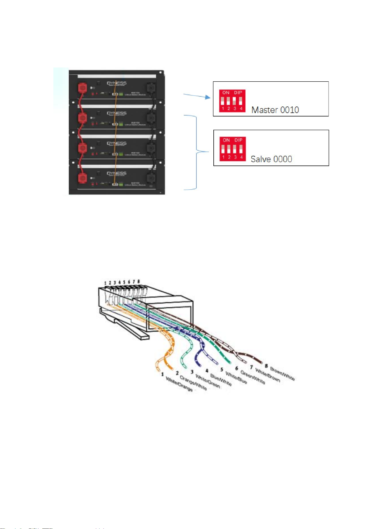
1. Poner el DIP Switch como previamente se ha descrito.
2. Pulsar el botón ON/OFF, dejándolo en la posición ON.
3. Pulsar y mantener durante 3 segundos el botón SW.
Cuando se encienda el indicador RUN, se habrá encendido la batería y encenderá el inversor.
Por otro lado, es posible encender el inversor desde el campo fotovoltaico.
2.3 Configuración del ISS 1Play TL M
El acceso al menú de configuración sólo está permitido a instaladores (personal cualificado).
Para ello es necesario registrarse como instalador en la aplicación web.
Prestar especial atención al elegir la batería adecuada a la hora de
realizar la configuración del inversor. Los fabricantes de baterías o del
inversor no tienen responsabilidad sobre los daños causados debido a la
incorrecta configuración. Por ejemplo, si se selecciona “Plomo-ácido”
como tipo de batería cuando la batería conectada es de litio, la batería
puede ser dañada o tener una degradación acelerada.
Una vez encendido el inversor, se tiene que acceder al inversor y configurar para que trabaje
con la batería B3/B4850/A48100/POWERBOX. Esto se puede hacer de dos formas distintas:
wizard y configuración avanzada. Si es la primera vez que se accede al inversor la
configuración de la batería se realizará mediante el wizard.
Para más detalles sobre como acceder al inversor, acudir al INGECON SUN STORAGE 1Play
“Manual de instalación y uso” disponible en la web de Ingeteam.
Configuración mediante el wizard:
Esta opción es la que se realiza durante la puesta en marcha del inversor. Seleccionar el tipo
de batería: DYNESS B3/B4850/A48100/POWERBOX.
Configuración mediante ajustes avanzados:
Acceder al inversor. Para realizar cualquier configuración es necesario poder acceder como
instalador. A continuación, ir a:
CONFIGURACIÓN > AJUSTES AVANZADOS > TIPO DE BATERÍA > DYNESS
B3/B4850/A48100/POWERBOX
Confirmar clicando en “Escribir”. Después, aparecerá un mensaje de confirmación.

Ingeteam
Uso y configuración del INGECON SUN STORAGE 1Play TL M conectado a la batería
B3/B4850/A48100/POWERBOX de DYNESS
ABH2010IMC26_.docx
9
3. REVISIÓN FINAL
En este capítulo se describen las instrucciones para revisar que la conexión y la configuración
se han realizado correctamente.
1) Verificar que el cable de comunicaciones CAN está conectado a la batería y al inversor.
2) Verificar que el inversor está encendido.
3) Al acceder al inversor, verificar que no muestra alarma “Communication Error with
BMS”.
3.1 Configuración de los parámetros de la batería
Después de realizar la revisión final, es recomendable configurar los niveles de SOC de la
batería en el inversor:
Modo de operación: conectado a red
Parámetro
Descripción
SOC Max
Estado de carga máximo para cargar las baterías desde la energía
fotovoltaica (%).
SOC Min
Estado de carga por debajo del cual no se permite la descarga de la
batería cuando la red está disponible. Es necesario alcanzar SOC
Recovery para reanudar el autoconsumo con aporte de batería.
SOC Recovery
Estado de carga por encima del cual se reanuda la descarga de la
batería, una vez que se viene desde SOC Min.
Se evita un ciclado excesivo de la batería alargando su vida útil.
Battery-Backup
En caso de que esté activada, ante una caída de la red se suministra la
energía necesaria a las cargas críticas desde las baterías y fotovoltaica.
Si se activa está funcionalidad es necesario configurar los parámetros
SOC Recx y SOC Descx.
En caso de que el modo de funcionamiento sea aislado o la función Battery-Backup esté
activada, se recomienda configurar los siguientes parámetros:
Modo de operación: aislado
Parámetro
Descripción
SOC Recx
Estado de carga por encima del cual se reinicia el suministro de energía a
las cargas, una vez que se viene desde SOC Descx (%)
SOC Descx
Estado de carga por debajo del cual se detiene el suministro de energía a
las cargas (%).
El inversor también puede ser configurado para gestionar una carga horaria de batería desde
red. Para más detalle, consultar el “Manual de instalación y uso” disponible en la web de
Ingeteam.

Contents
1INTRODUCTION ..................................................................................................................................11
2B3/B4850/A48100/POWERBOX BATTERY ..........................................................................................12
2.1 Connecting the battery pack to the inverter.................................................................................12
2.1.1 Wiring of DC wire..................................................................................................................12
2.1.2 Wiring of CAN communication cable....................................................................................13
2.2 Switch on the inverter from battery .............................................................................................16
2.3 Configuration of the ISS 1Play TL M ..............................................................................................16
3FINAL CHECK.......................................................................................................................................17
3.1 Configuration of the battery settings............................................................................................17
ES
EN

Ingeteam
Use and settings of the INGECON SUN STORAGE 1Play TL M working with
B3/B4850/A48100/POWERBOX of DYNESS
ABH2010IMC26_.docx
11
1 INTRODUCTION
This document describes the process to connect and configure INGECON SUN STORAGE
1Play TL M (ISS 1Play TL M) to work with the battery B3/B4850/A48100/POWERBOX of
DYNESS.
Ingecon Sun Storage 1Play TL M DYNESS B4850
The ISS 1Play and the battery B3/B4850/A48100/POWERBOX equipment can be used in the
following type of installations:
•Stand-alone installations
•UPS installations
•Self-consumption installations
The minimum version of the ISS 1Play TL M to work with the B3/B4850/A48100/POWERBOX:
Minimum Firmware Version for the ISS 1Play TL M:
•Inverter: ABH1007_J

Ingeteam
Use and settings of the INGECON SUN STORAGE 1Play TL M working with
B3/B4850/A48100/POWERBOX of DYNESS
ABH2010IMC26_.docx
12
2 B3/B4850/A48100/POWERBOX BATTERY
This chapter describes the process of connection, switch on and configuration of the ISS 1Play
TL M to work with the B3/B4850/A48100/POWERBOX battery.
2.1 Connecting the battery pack to the inverter
Please, consider the following technical notes:
1) The inverter must be OFF before connecting the battery to the inverter.
2) Connect the DC power wires with 10mm2.
3) In this manual the CAN communication is done with an Ethernet wire.
2.1.1 Wiring of DC wire
The DC wiring must have terminals on the inverter side, and it must be connected to the inverter
as follows:
ISS 1Play TL M
1. Pass the wires through the dedicated cable grommet, respecting the polarities.
2. Remove the M5 bolts and connect the wiring to the terminal marked as J105 BATTERY
+ and J106 BATTERY -
3. Tighten the M5 bolts with a torque of 2.5Nm to ensure they are properly fastened. It is
important to not apply excessive tightening torque.
4. Check that the connection is tight

Ingeteam
Use and settings of the INGECON SUN STORAGE 1Play TL M working with
B3/B4850/A48100/POWERBOX of DYNESS
ABH2010IMC26_.docx
13
2.1.2 Wiring of CAN communication cable
The communication between the battery and the inverter can be done by an Ethernet wire that it
connects to the “IN” connector of the battery.
This can be done, for example, with an Ethernet wire. Connecting the RJ45 connector of the
wire to the battery connector.
The DIP Switch of the battery that is directly communication with the inverter must be in this
position:
In case of a storage system with two or more batteries, the DIP Switch of the rest of the
inverters should be in this position:

Ingeteam
Use and settings of the INGECON SUN STORAGE 1Play TL M working with
B3/B4850/A48100/POWERBOX of DYNESS
ABH2010IMC26_.docx
14
For example. In a storage system with 4 x A48100 batteries, the DIS Switches would have to be
placed as follows:
On the other hand, the ISS 1Play TL M requires a two-wire CAN cable. The wires can be
obtained by cutting the end of the Ethernet cable with the RJ45 connector.
It is necessary to identify which of the wires is pin 4 and pin 5. This can be done by viewing the
wire colors of pins 4 and 5 on the RJ45 that is connected to the battery. The following picture
shows the position of pins 4 and 5 of an RJ45 connector:

Ingeteam
Use and settings of the INGECON SUN STORAGE 1Play TL M working with
B3/B4850/A48100/POWERBOX of DYNESS
ABH2010IMC26_.docx
15
After identifying the pin 4 and pin 5. Both wires of the communication cable must be connected
to the J8 terminal of the inverter.
ISS 1Play TL M
1. Pass the CAN communication cable though the dedicated cable
gormet.
2. Connect both wires to the terminal J8 BMS as shown in the previous
figure, respecting the printed instructions on the screen-printed
electronic card (CAN_L, CAN_H):
3. Guide the cable and hold it if necessary on the plastic support.
4. Check that the connection is tight.
Ethernet cable
ISS 1Play TL M
Pin 4
J8 BMS CAN_H
Pin 5
J8 BMS CAN_L
Once all the previous steps have been followed and the inverter is properly wired, the
commissioning of the inverter can be done.

Ingeteam
Use and settings of the INGECON SUN STORAGE 1Play TL M working with
B3/B4850/A48100/POWERBOX of DYNESS
ABH2010IMC26_.docx
16
2.2 Switch on the inverter from battery
The inverter can be supplied from the B3/B4850/A48100/POWERBOX battery, without previous
configuration. To do so, follow these steps:
1. Put the DIP Switch as previously described.
2. Press the ON/OFF button and put it in ON position.
3. Press and hold the SW button for 3 seconds.
Once the RUN indicator turns ON the battery will turn on.
On the other hand, it is possible to turn on the inverter through the PV field.
2.3 Configuration of the ISS 1Play TL M
Please be careful to choose the right battery type when you set up the
configuration in your inverter. The battery or inverter manufacturers have
no responsibility on the damages caused due to incorrect configurations.
For instance, if you select “Lead-acid” as a battery type in the inverter
configuration and the battery being used is “Lithium-ion”, the battery might
get damaged or experience performance degradation.
The inverter can be configured to work with B3/B4850/A48100/POWERBOX though two
different ways: wizard or advanced settings. If the configuration is done during the
commissioning, the configuration will be done through the wizard.
For more details of how to access the inverter web interface, check the Installation and
Operation Manual of the INGECON SUN STORAGE 1PLAY TL M.
Configuration through the Wizard:
This option is the one during the commissioning. Choose the type of battery: DYNESS B3
/B4850/A48100/POWERBOX.
Configure through the Advanced Settings:
Access to the web interface of the inverter. To perform any configuration change, the installer
access level is needed. When the access level is obtained, go to:
CONFIGURATION > ADVANCED SETTIGNS > TYPE OF BATTERY > DYNESS B3/
B4850/A48100 /POWERBOX
Confirm the desired selection by pressing the “Write” button. A message to confirm the
modification will appear.

Ingeteam
Use and settings of the INGECON SUN STORAGE 1Play TL M working with
B3/B4850/A48100/POWERBOX of DYNESS
ABH2010IMC26_.docx
17
3 FINAL CHECK
This chapter describes the instructions to check that all the connections and settings have been
successfully done.
1) Verify that the CAN communication cable from the battery to the inverter is connected.
2) Verify that the inverter is on.
3) Access to the inverter and verify that there is no “Communication Error with BMS”
alarm.
3.1 Configuration of the battery settings
After the commissioning or the final check, it’s recommended to configure the SOC levels in the
inverter.
Operation mode: connected to grid
Setting
Description
SOC Max
Maximum state of charge for charging the batteries from the photovoltaic
energy (%).
SOC Min
Charge status under which battery discharge is not allowed when the grid
is available. SOC Recovery must be reached to resume the self
consumption with battery input.
SOC Recovery
Charge status above which the battery discharge resumes, once coming
from SOC Min.
This prevents excessive cycling, extending their work life.
Battery-Backup
In the event of a power outage, the energy required for critical loads is
supplied from the batteries and PV array. If this function is activated, the
SOC Recx and SOC Descx parameters need to be configured.
If the operation mode is stand alone or the Battery-Backup function, it’s activated. It’s
recommended to configure the following settings.
Operation mode: off grid
Setting
Description
SOC Recx
Charge status above which the power supply to the critical loads is
restarted, once coming from SOC Descx (%)
SOC Descx
Charge status below which the power supply to the critical loads when the
grid is not available and the Battery- Backup function is enabled (%)
The inverter allows managing the battery charge daily through the scheduling. By default, this
function is disactivated. For more detail, check the Installation and Operation Manual of the
INGECON SUN STORAGE 1PLAY TL M.
Other manuals for INGECON SUN STORAGE 1Play TL
4
Table of contents
Languages:
Other Ingeteam Storage manuals