Ingos RVO 400 User manual

INGOS Ltd. Laboratory Instruments division Page 1
INGOS Ltd.
ROTARY VACUUM
EVAPORATOR
RVO 400
User manual
Producer: Laboratory Instruments division of INGOS Ltd.
Supplier and service: INGOS Ltd. Tel.: + 420 296 781 683
K Nouzovu 2090 + 420 296 781 692
143 16 Prague 4 Fax: + 420 244 403 051
e-mail: instruments@ingos.cz, pristroje@ingos.cz
www: ingos.cz

INGOS Ltd. Laboratory Instruments division Page 2

INGOS Ltd. Laboratory Instruments division Page 3
1. INTRODUCTION
Innovated
Rotary vacuum evaporator RVO 400 is new advanced model of the company INGOS
Ltd.. RVO 400 is first model fitted with system designed for the control and communication by PC
with the possibility to data entry of pre-set values and date processing while evaporating . Is noted for
affability value in-use and compact construction. Innovated design offer users comfort and safety
using the remote control and safety bath cover. Optional is possible to equip RVO 400 with the
regulation in accordance by steam temperature .
1.1 Apparatus use and specifications
Rotary vacuum evaporator RVO 400 is designed for low-pressure evaporation at the pre-set value
of the heating bath temperature and at the pre –defined constant mixing process of the solution to be
vaporised. The vapours exhausted condense in a vertical or diagonal cooler and are collected into a
flask.
The apparatus is fitted with a digital vacuum control and measuring system. Vacuum ratio
is driven by diaphragm vacuum pump control.
User comfort assure heating bath equipped with motorized lift and manually tilted rotary
casing head.
Rotation of the evaporating flask, height of the heating bath, steam temperature , the
vacuum ratio and length of evaporation can be digitally set and controlled using the
Keyboard or PC. All controlled values can be stored in memories.
Standard glass assembly can be adapt or enlarged on request.
1.2 Technical characteristics
Evaporating flasks ................................................. 20 – 4000 ml
Rotation speed ......................................................0, 10 up to 280 rpm
Heating bath capacity (without flasks) …………. max. 4000 ml
Bath temperature ..................................................max. 100°C for water filling
max. 180°C for oil filling
Regulation accuracy .............................................. ±1°C up to 100°C *
±3°C up to 180°C *
Pressure measurement…………………………… absolute
Pressure difference ................................................ adjustable 1-500 mbar
Power supply ........................................................ 230V, ±10%, 50Hz
Power input ..........................................................max.2000 W Power input
Dimensions (w x h x d) ........................................ 650 x 900 x 360 mm (including glass)
*
in resting state
1.3 Symbol Explanation
- hot surface

INGOS Ltd. Laboratory Instruments division Page 4
2. TECHNICAL DESCRIPTION
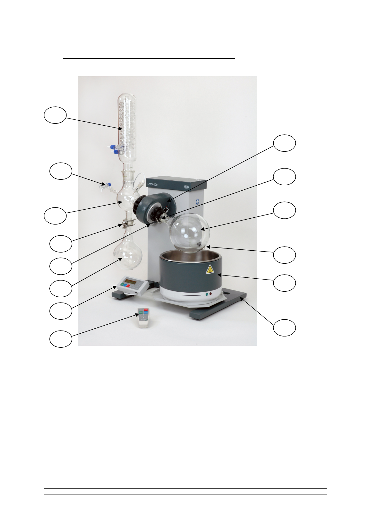
Individual parts of the evaporator and their location can be seen on fig. 1.
1. Stand 9. Filling pipe with valve
2. Rotary casing head 10. Fixed clip
3. Heating bath 11. Head tilt stick
4. Suck pipe 12. Lift top position stopper screw
5. Ball adapter 13. Keyboard (see Fig.6)
6. Condenser 14. Wireless remote control (for request)
7. Receiving flask 1000 or 2000 ml, ball KS 35/20
8. Round bottom flask 1000 or 2000 or
4000 ml, point NZ 29/32
Fig.1 Location of individual parts of RVO
For complete list of basic accessories see paragraph 7.2.1.
1
3
1
2
8
4
2
1
4
1
3
7
1
1
10
5
9
6

INGOS Ltd. Laboratory Instruments division Page 5
3. STARTING OF OPERATION
3.1 Unpacking of the apparatus
Unpack the apparatus from the transport package, check the evaporator’s surface and check all
items according to the delivery note. If the apparatus is damaged or if an item is missing, contact
your supplier or the manufacturer. Caution: apply silicone Vaseline to the all joints of the glass
assembly.
3.2 Apparatus assembly
1. Keyboard can be hanged on the left fourpod leg of the stand apparatus or can be laid beside it.
Plug connection cable in to the keyboard and to the socket at the back of apparatus marked
KEYBOARD (fig. 2).
2. Place the heating bath on the lift table fig. 1, insert the bath cable into the socket under the
mains switch (fig. 2 pos.10) and plug the connector of the bath temperature sensor into the
socket (fig. 2 pos.3) marked TAC THERMOMETER
.
3. Pour approximately 1 l of liquid into the heating bath.
Fig. 2. Connectors

INGOS Ltd. Laboratory Instruments division Page 6
4. Rotation blocking knob, which is placed on the rotary casing head, set to the ”Lock” position
(marking by red point) (for easier locking try to turn the casing a little). Insert suck pipe in to the
rotary casing until the sitting touches the plastic collar. Than tighten the nut on the rotating
casing. Finally ”Unlock” the blocking knob (marking by green point).
5. The opposite side of the head with the rotary casing contains a fixed housing with a nut. Unscrew
the nut (fig. 3 pos.2), put it on the fitted part of the ball adapter (fig. 3 pos.1), insert the bead-type
securing ring (fig. 3 pos.3) in such a way that it can latch behind the fitted part of the ball adapter.
Check that the gufero sealing, treated with silicone Vaseline, has been inserted inside the fitted part
(fig. 3 pos.4), its open side should face out of the fitting. Check that the flat sealing (fig. 3 pos.5)
has been inserted in the casing and put carefully the ball adapter with gufero and nut on the suck
pipe (fig. 3 pos.6), push the ball adapter until it stops and tighten the nut properly (fig. 3 pos.2).
The spherical joint of the ball adapter faces down.
6. Do not forget to apply silicone Vaseline to all glass parts joints.
7. Install the condenser into the joint in the upper part of the ball adapter. The upper outlet of the
condenser serves for the connection of the vacuum source. Connect the outlet of the condenser to
the socket for the measurement of vacuum, marked VACUUM, and to the vacuum source with the
help of a ”T” union. Other outlets serve for connection of cooling water.
8. Attach the receiving flask with ball joint to the ball adapter with the help of a fixed clip, tighten
properly.
9. Put the round bottom flask on the pipe and secure it with a wire combi-clip.
10. Insert the filing pipe with a valve (valve closed) into the ball adapter.

INGOS Ltd. Laboratory Instruments division Page 7
1. Ball adapter or diagonal condenser 5. ------
2. Nut 6. Housing
3. Bead-type securing ring 7. Suck pipe
4. PTFE sealing
Fig. 3a. Ball adapter sealing (chemical resistant)

INGOS Ltd. Laboratory Instruments division Page 8
1. Ball adapter or diagonal condenser 5. Flat sealing
2. Nut 6. Housing
3. Bead-type securing ring 7. Suck pipe
4. Gufero sealing 35/22/10
Fig. 3b. Sectional assembly view (low chemical resistant)

INGOS Ltd. Laboratory Instruments division Page 9
1. Cooling water outlet 3. “T” tube connection
2. Cooling water inlet 4. Vacuum connection
Fig. 4. Tube connection scheme
11. Connect the main cord. (fig. 2)
12. Lift the heating bath using the lift to its working position. At the bath top position adjust the lift
stopper and fill in the liquid in the heating bath in such a way that the round-bottom flask can be
sufficiently immersed in the liquid. The maximum liquid level is approximately 20 mm below the
edge of the heating bath. Flask can be immerse and emerge by tilt the rotary casing head. For tilt use
stick on the left side of the apparatus. When tilt the head move stick carefully, pay attention to
glass equipment.
13. When removing the round bottom flask, release the vacuum first (e.g. use the filling pipe valve).
For easier manipulation use the rotation blocking knob to lock the rotation. Carefully unscrew
the wire combi-clip, until the flask is released. During the flask removing, work with caution.
14. When the vacuum control is desired, connect the mains cable of vacuum pump into the socket on the
back side of the apparatus. In this case connection between condenser vacuum outlet and vacuum
measurement socket has to be established!

INGOS Ltd. Laboratory Instruments division Page 10
1. Cooling water outlet 4. Controlled vacuum pump plug socket
2. Cooling water inlet 5. ”T” union
3. Vacuum sensor connection 6. Vacuum pump
Fig. 5. Connection plan for vacuum control
Caution : It is not possible to use the glass part if it features visible scratches or any other
defects ! W hen controlling the vacuum, only the diaphragm vacuum pump with maximum
input 650 W, can be plugged in the evaporator!

INGOS Ltd. Laboratory Instruments division Page 11
3.3 Apparatus control
The device is started up by switching the mains switch on. Upon startup, the display is lighted
temperature Tac and pressure Pac is displayed. By repeated pressing the DISPLAY button the
initial reading changes to Time.
Buttons and control the lift movement and setting the values of the display. The upward
movement of the solution is limited by an adjustable limit switch placed on the right side of the device
stand (see fig. 1 pos.12). It is operated by means of a black knob. The downward movement of the
solution is limited by a fixed limit switch. CAUTION! During upward movements of the warming
solution, make sure that the solution does not overflow or that the glass parts do not get
damaged.
Fig. 6. Keyboard
3.3.1 RPM setup
Pressing the ROTATION button once displays RPM setting on the display (by arrows) and
pressing it twice starts the rotation. Pressing it once more the rotation stops. Pressing then the
DISPLAY or ESC buttons returns the device into the initial display mode.
Another pressing the ROTATION button displays again the RPM setup and one more
pressing it stops the rotation. Correct operation is indicated by top right corner of the button
lighting. Always make sure that the button of rotation blocking is in the position
UNLOCKED. (If you start rotation with the blocking button in the LOCKED position, the case
with the tube does not start rotating, just starts rotation lighting will flash. The apparatus enables
you to set both directions of the rotation. The opposite direction of the rotation is indicated with the
- minus sign.

INGOS Ltd. Laboratory Instruments division Page 12
3.3.2 Temperature setting
In case the regulation is set according to the solution temperature Tac in the MENU position
Heat, pressing the HEATING button once displays the solution temperature setting (by the
arrows) pressing it once more, the solution heating is started. Pressing the button still once more
switches the heating off. Pressing then the DISPLAY or ESC buttons returns the device into the
initial display mode.
Press HEATING once more and temperature setting displays again and another pressing the
button switches the heating off. Correct function is indicated by top right corner of the button
lighting in case of a failure the light starts flashing.
If the vapor sensor is installed and in the MENU mode in Heat the regulation is set according
to Tvap and the display is in the temperature setting mode, then the Tvap vapor temperature
setting (optional) changes and the cooler temperature Tsol (optional) is only indicated.
If any of the sensors is not installed for the corresponding temperature NO is displayed.
Note: the solution temperature Tac must be set accordingly higher than the required vapor
temperature Tvap.
Temperature gradient setting
After pressing MENU button or choose the option Heating F/G, press ENTER,
choose FIX or GRADIENT (there is visible Fix or Grad on display). After choosing GRADIENT
you can see the temperature (on the left) and time (on the right). Bath temperature is set by
pressing arrows, than press ENTER, then set time (by arrows), press ENTER, set time (minutes),
press ENTER - this is how to set time of the constant temperature. Press the HEATING button,
temperature is shown on the left, time on the right. In total it is possible to set 20 changes in
temperature during evaporating. When the setting is finished, confirm set value by ENTER. Press
the DISPLAY and ENTER buttons and the evaporator will start the program. When the
HEATING button is pressed repeatedly, it is possible to browse through the set values of
temperature gradient. In case of all changes of set values, it is necessary to confirm all the values on
display by pressing the ENTER button.
3.3.3 Vacuum setting
Pressing the VACUUM button once displays the vacuum value setting (arrows), pressing it
twice starts vacuum control (if the vacuum pump is installed, see fig. 5). Pressing it once more
switches the vacuum control off. Pressing then the DISPLAY or ESC buttons returns the device
into the initial display mode.
Pressing the VACUUM button again, the display will show vacuum value setting again and
another pressing the button shall switch the vacuum control off. Correct operation is indicated by
top right corner of the button lighting.
Vacuum gradient setting
After pressing MENU button or choose the option Vacuum F/G, press ENTER,
choose FIX or GRADIENT (there is visible Fix or Grad on display). After choosing GRADIENT
you can see the vacuum (on the left) and time (on the right). Vacuum is set by pressing arrows,

INGOS Ltd. Laboratory Instruments division Page 13
than press ENTER, then set time (hours) by arrows, press ENTER, set time (minutes), press
ENTER - this is how to set time of the constant vacuum. Press the VACUUM button, vacuum is
shown on the left, time on the right. In total it is possible to set 20 changes in temperature during
evaporating. When the setting is finished, confirm set value by ENTER. Press the DISPLAY and
ENTER buttons and the evaporator will start the program. When the VACUUM button is pressed
repeatedly, it is possible to browse through the set values of vacuum gradient. In case of all changes
of set values, it is necessary to confirm all the values on display by pressing the ENTER button.
3.3.4 ENTER button function
In all modes apart from MENU, pressing the corresponding button switches ROTATION,
HEATING, VACUUM on/off. After recalling memory LOAD 1-4, functions of ROTATION,
HEATING, VACUUM and TIME switch on/off.
ENTER in the MENU mode is the selection confirmation.
3.3.5 DISPLAY button function
Pressing the button cyclically changes the display mode and the arrows are active as lift movement
controls.
1. Tac + Pac
2. Tvap + Tsol - if installed
3. Timer
Pressing the DISPLAY button also overrides other display readings (Rotation, Vacuum, Heating).
3.3.6 MENU/ESC button function
MENU Timer
Heating F/G FIX/ Gradient
Vacuum F/G FIX/ Gradient
Heat Tac / Tvap
Load memo Load #1
Load #2
Load #3
Load #4
Save memo Save #1
Save #2
Save #3
Save #4
Delta P
Atmosf P
Setting Pressure units Torr / mBar
Temperature units °C / K
Beep on/off
Default yes/no
Menu items:
Timer - setting time countdown. If the time 00:00 is set, the operation time is not limited.
When the time set is reached, the heating switches off, the solution moves down,
rotation stops and also the vacuum pump is switched off. In case of failure, or
stopping of the rotation or heating, the device switches off.
Heat regulation - setting the heating regulation mode according Tac-solution temperature or Tvap-
vapor temperature.

INGOS Ltd. Laboratory Instruments division Page 14
Load Memo - reading 4 device setups (the memory content is copied into the actual setup).
Save Memo - storing 4 device setups (writing the actual setup into the memory).
These parameters are stored : Pac,Tac,Tvap, Tac/Tvap regulation type, RPM, timer.
Delta P - setting the pressure hysteretic for regulation within 1 to 500 mBar (setting the
difference between switching the vacuum pump of and off)
Atmosf P - if the absolute sensor is installed (optional) it shows the absolute pressure, it may not
be edited.
- if absolute sensor is not installed, the ambient pressure may be set manually
according to a calibrated barometer. If 0 is set, the display shows the absolute value of
the relative pressure.
Setting - Setting parameters for the display module (units, lighting, contrast, beep, and return
to factory setup).
The values are stored directly in the display module and are valid for the specific
module.
ENTER selection confirmation
ESC return
After the device is switched on or when switching memory, rotation and heating the warming solution
is switched off for safety reasons. We recommend controlling the RPM value set before you start the
rotation.
3.3.7 Remote control (optional)
Fig. 7. Remote control
The LIFT button activates the arrows for lift movement (after a longer standby time it is necessary to
activate them again)

INGOS Ltd. Laboratory Instruments division Page 15
The ROTATION button displays RPM setting (by arrows) upon the 1
st
pressing, upon the 2
nd
it starts
rotation. If pressed once more, the rotation stops. Correct operation is indicated by top right corner of
the ROTATION button lighting – located on the keyboard with the display.
The HEATING button displays a keyboard for temperatures Tac and Tvap setting on the monitor (by
arrows) according to the regulation time set in MENU upon the 1
st
pressing. The 2
nd
pressing
switches on the heating. If pressed once more, the heating is switched off. Correct operation is
indicated by top right corner of the HEATING button lighting – located on the keyboard with the
display.
The VACUUM button displays vacuum value setting (by arrows) upon the 1
st
pressing, upon the 2
nd
it
starts vacuum control (if the vacuum pump is installed, see fig 5.) If pressed once more, the vacuum
control is switched off. Correct operation is indicated by top right corner of the VACUUM button
lighting – located on the keyboard with the display.
The Display, after some 10 idle seconds switches to the initial readings.

INGOS Ltd. Laboratory Instruments division Page 16
3.3.8 Operating by PC (accessories by request)
Install the program from CD to PC first.Interconnect PC and RVO 400 by the delivered link
cabel(seriál port). Start program and now you can kontrol the instrument using PC.The changed
parameters by PC will be rewritten also by display of keyboard and reversaly.
PC requirements: Windows,office,seriál port or USB converter-seriál port.
3.3.9 Vacuum evaporating report by PC(accessories by request)
Select under PC program mode of evaporating run, select name and enter. After push-button
operation START the program is runing.For the each one data jogging you can create new databáze or
select primary and the data are storaged as continuation storaged data before.
The rekord consist of instrument setting and recording at selected scaning intervals.
* No = Senzore arn´t detected other way are displayed current values
▀After setting required values enter - Write
Fig. 8. Monitor PC
Flask rotation
Create
database
Lift operating
Getting of
storrings
memories1-4
Error
reporting and
deletion
START
STOP
Communication port
selection
Err =
Communication error
OK = free and clear
Program
termination
Bath temperature
*
H
eating temperat.
*
Vapour tempera.
*
Temperatureof
coolers vapour *
Vacuum*
Vacuum setting▀
Bath and vzpour
temperature
setting ▀
Setting of run time
Static pressure setting in case
without absolute sensor
Static pressure
Pressure diference setting
between ON and OFF of
vacuum pump
Time-like
interval of
scaning

INGOS Ltd. Laboratory Instruments division Page 17
4. MAINTENANCE
4.1 Apparatus maintenance
Do not leave the evaporator surface contaminated from corrosive substances. It could damage the
evaporator coating. Clean the contamined surface with a clean soft cloth. The cloth may be moistened
but not wet. It is also possible to use ordinary washing means for cleaning purposes. It is forbidden to
clean the heating bath with the means which could spoil its smooth surface. In case of sediments of
turning,impurities, particulates of water rusts ,use the cleaning compounds for cleaning of furning or
mellow solution of HCL. In process of cleaning use the protective means recommended by producer
of applied cleaning compounds.
Caution: Disconnect the apparatus from the network while cleaning it with a wet cloth!
4.2 Sealing replacement
Disassemble the condenser, remove the releasing pipe with the valve, remove the ball-and-
socket ground joint flask, release the nut of the ball adapter and carefully remove the actual adapter.
Release the gufero sealing, clean the ball adapter, slightly apply silicone Vaseline onto the new sealing
and mount it into the ball adapter. The sealing cavity faces out of the ball adapter. If necessary, replace
also the flat sealing between the ball adapter and the head fitted with a rotary casing. Perform the
assembly according to the point 3.2. Apply a light layer of silicone Vaseline to the gufero sealing
approximately after 80 operation hours (more often if necessary).
5. DEFECTS AND TROUBLESHOOTING
5.1 Leakage
The main cause of leakage is usually an incorrect sealing assembly. At first you should check that
all joints have been installed correctly. If it is the case, disassemble the glass and verify the condition
of the ball adapter sealing and flat sealing, if necessary replace them. Carefully assemble according to
the instructions, switch the rotation ON and start the vacuum pressure up.

INGOS Ltd. Laboratory Instruments division Page 18
5.2 Other failures
The apparatus does not respond when you switch it ON. Check fuses, possibly replace with new
ones featuring the same parameters (fig. 2, T 0.5A and T 10A).
The window of the rotation key is
flashing, rotating parts are not moving. Ensure that Rotation blocking knob is set to ”Unlock” and than
press rotation key again.
The window of the rotation key is flashing. Check that there is not anything
which could impede the flask from its rotation (manually), switch the mains switch OFF and ON and
press the rotation key again.
The window of the temperature key is flashing. This indicates that the
temperature sensor have been connected incorrectly. Check the sensor connection, quantity of liquid in
the heating bath and switch the main switch OFF and ON and press the temperature key again.
Controlled vacuum pump is not running, even the pump mains cable is correctly plug in the rear of
evaporator as well as vacuum connecting hose. Check the vacuum pump fuse, possibly replace it with
new one featuring the same parameters (fig. 2, T3,15A).
6. SAFETY AND OPERATION CONDITIONS
6.1 Operation safety
Ensuring of rotation of the sample to be vaporized: Current protection of the driving
motor. If the
resistance against rotation has increased above the
prespecified limit, the driving motor voltage will be
disconnected. (This situation will be signaled by the
flashing of the rotation LED)
Protection of the heating bath lift: Friction coupling between the driving motor and
lifting equipment. In the case of an increase in resistance
during the lifting of the bath above the specified limit the
friction coupling could slip.
Protection of bath heating: Electronically by means of a thermal protection
Against overheating. There will not be any heating if the
incorporated sensor of the heating bath has been
connected or if the difference of temperatures between
sensors rises above the limit pre-specified by the
manufacturer. (This situation will be signaled by the
flashing of the LED for heating)

INGOS Ltd. Laboratory Instruments division Page 19
6.2 Operation conditions
The apparatus is designed for the work under ordinary laboratory conditions at temperatures of 10
to 30°C and air humidity up to 80% . The power supply is 230 V, 10 A, 50 Hz. The inlet cord should
be connected into a socket circuit featuring protection from 10 A or 16 A (diaphragm vacuum pump
connected). The inlet cord cannot be in contact with the heating bath. The socket designed for the
connection of the heating bath is designed exclusively for this bath. Oil used in the bath must be
designed for a temperature of at least 180°C. The bath volume shall not exceed 2 l.
It is forbidden to handle any bath which has been heated to a temperature exceeding 40°C in any
other way than by using the apparatus lift. If you want to fill the liquid into the heating bath, always
switch the vaporized sample rotation OFF. For temperatures up to 100°C use water as the filling of the
heating bath (with regard to its higher thermal capacity).
Caution! If you are replacing the round-bottom flask after the vaporized solution has become
thicker, pay particular attention and if it is not possible to remove the flask easily from the cone, carry
out any other handling only after the cooling of the bath.
Caution! If you use oil as the filling of the heating bath, the heating bath must be properly dried
before its being filled.
Caution! If you are working with oil heated above 100°C, you must ensure that no
water can enter into the oil. If you are replacing the round-bottom flask, pay particular
attention that no water drops shall enter into the oil. While working, use personal protection
equipment (goggles, gloves, coat and shoes).

INGOS Ltd. Laboratory Instruments division Page 20
7. ACCESSORIES AND SPARE PARTS
7.1 Basic accessories (comes with evaporator)
Inlet cord Glass assembly
Round bottom flask (1000, 2000 or 4000 ml) NZ29/32
Receiving flask (1000 or 2000 ml) KS 35/20
Suck pipe
Ball adapter
Vertical condenser
Filling pipe with a valve
3 pieces of GL14 connection fitting
Sealing: gufero sealing 35/22/10 (Fig. 3b, pos. 4),
PTFE sealing (Fig. 3a, pos. 4)
Fixed clip Keyboard
Adaptor Keyboard
Cables 0.4 and 2m
Tubing coupler PA vacuum tubing (100, 110 a 150cm)
Main inlet cord
7.2 Other accessories
7.2.1 Glass accessories (Fig. 7)
4SKL0021 Evaporating flask 50 ml, joint NZ29/32
4SKL0025 Evaporating flask 100 ml, joint NZ29/32
4SKL0022 Evaporating flask 250 ml, joint NZ29/32
4SKL0023 Evaporating flask 500 ml, joint NZ29/32
4SKL0004 Evaporating flask 1000 ml, joint NZ29/32
4SKL0003 Evaporating flask 2000 ml, joint NZ29/32
4SKL0012 Evaporating flask 4000 ml, joint NZ29/32 (only RVO400)
4SKL0017 Receiving flask 250 ml, joint KS35/20
4SKL0024 Receiving flask 500 ml, joint KS35/20
4SKL0006 Receiving flask 1000 ml, joint KS35/20
4SKL0034 Receiving flask 2000 ml, joint KS35/20
4SKL0005 Vertical condenser
4SKL0033 Diagonal condenser
4SKL0020 Dry ice trap
4SKL0001 Filling pipe with a valve - short
4SKL0002 Filling pipe with a valve - long
4SKL0008 Ball adapter
RO4810 Ball adapter including steam temperature sensor
RO3212 Suck pipe
Other manuals for RVO 400
1
Table of contents
Other Ingos Laboratory Equipment manuals
Popular Laboratory Equipment manuals by other brands

enviromental express
enviromental express AutoBlock Fill Operation & instruction manual

Pasco Scientific
Pasco Scientific ME-6814 Instruction manual and experiment guide

ROBOfiber
ROBOfiber 8INJ-GE-125R user manual

BioLAB
BioLAB BFSD-502 Operation manual

N-BIOTEK
N-BIOTEK NB-205LF operating manual

bioMerieux
bioMerieux Air IDEAL 3P user manual