Ingos RVO 400 User manual

INGOS Ltd. RVO 400 11.2.2019 Page 1
INGOS Ltd.
ROTARY VACUUM
EVAPORATOR
RVO 400
User manual
Producer: INGOS Ltd.
Supplier and service: INGOS Ltd. Tel.: + 420 225 983 400
K Nouzovu 2090 + 420 225 983 409
143 00 Prague 4 Fax: + 420 244 403 051
e-mail: instruments@ingos.cz
www: ingos.cz

INGOS Ltd. RVO 400 Page 2
1. INTRODUCTION
The digitalized and programmalle rotary vacuum evaporator is another improved model by the
Czech company INGOS. It allows communication and PC with evaporative data recording and
discrete and proportional vacuum regulation. It features user-friendliness with intuitive graphics and
Compaq robust design. For convenience and operator safety extra remote control can be used on
request. On measuryent request the device can be fitted with vapor temperature control, cooling water
temperature, protection elements, vacuum pumps, chiller cooling and other accessoris.
1.1 Apparatus use and specifications
Rotary vacuum evaporator RVO 400 is designed for low-pressure evaporation at the pre-set value
of the heating bath temperature and at the pre – defined constant mixing process of the solution to be
vaporised. The vapours exhausted condense in a vertical or diagonal cooler and are collected into a
flask.
1. The apparatus is fitted with a digital vacuum control and measuring system. The vacuum pump is
switched from the socket on the instrument or for proportional by control cable.
2. Easy manipulation is allowed by electric bath lift and the option of manual tilting of the head
with a station case.
3. Rotation of the evaporating flask, heating bath temperature, steam temperature , the
vacuum ratio and length of evaporation can be digitally set and controlled using the
keyboard. All controlled values can be stored in RVO memories. SW updates over
WIFI.
4. Standard glass assembly can be adapted or enlarged on request.
1.2 Technical characteristics
Evaporating flasks
20 -4 000 ml
Rotation speed
0 - 300 rpm
Rotation bidirectional cyclic
Heating bath capacity max. 4000 ml
Bath temperature max. 100 °C for water filling
max. 180 °C for ordinary oil filling
max. 210°C for special oil filling
Regulation accuracy (in resting state) ±1 °C up 100 °C
±2 °C up 210 °C
Pressure measurement absolute
Pressure diference adjustable 1-500 mbar
Temperature and pressure gradient programmable
Power supply 230 V, ±10 %, 50 Hz
Power on 60°C 0,1 kW/ hod
Power on 90°C 0,3 kW/ hod
Switching power of the vacuum pump max. 650 VA
Power consumption max. 2000 VA
Weight without glass 20 kg
Dimensions (w x h x d) 650 x 900 x 360 mm (including glass)
1.3 Symbol Explanation
Hot surface

INGOS Ltd. RVO 400 Page 3
2. TECHNICAL DESCRIPTION
1 Stand 9 Filling pipe with valve
2 Rotary casing head 10 Fixedclip
3 Heating bath 11 Vacuum and cooling water output
4 Suckingpipe 12 Adjust screw for setting the lift upper stop
5 Ball adapter 13 Keyboard
6 Condenser 14 Lever for tilting head
7 Receivingflask 15 Rotation lock
8 Evaporation flask 16 Fixed and downloading nut
Fig. 1 Basic description
1
3
1
2
8
4
2
1
4
1
3
7
1
1
10
5
9
6
1
5
16

INGOS Ltd. RVO 400 Page 4
3. STARTING OF OPERATION
3.1 Unpacking of the device
Unpack the device from the transport package, check the evaporator’s surface and check all
items according to the delivery note. In case of damage to the device, or if an item is missing,
contact your manufacturer or your supplier. Remove from the cooler shipping fill (remove the
jammed filler with acetone), otherwise the vacuum pump can get blocked!
Caution: apply silicone Vaseline to the all joints of the glass assembly, or use a PTFE insert into
cones.
3.2 Device assembly
1. Place the keyboard on the holder left foot of the stand device, connect the cable from the
left foot. If you want to put the keyboard next to the device, connect keyboard with
connector on the back of device (Figure 2).
2. Place he rating bath on the lift table fig.1, insert the bath cable into the socket under the
mains switch (fig. 2) and plug the connector of the bath temperature sensor into the
socket (fig. 2) marked BATH THERMOMETER
.
3. Pour water (oil) into the heating bath.
KEYBOARD
BATH THERMOMETER
VAPORTHERMOMETER
REMOTE CONTROL
COOLANT THERMOMETER
VACUUMCONTROL
T0,5A T10A
VACUUM
PC
VACUUM
PUMP
T3,15A
1
Power supply
8
Keyboard connector
2
Socket for bath
9
Remote control connector
3
Socket for discreetly controlled vac. pump
10
Bath temperature connector
4
Fuse vacuum pump
11
Connector vapor temperature
5
Fuse supply
12
Coolant temperature connector
6
Fuse for electronics
13
Connector for proportional vacuum control
7
Connector for PC connection
14
Outlet vacuum measurement
12
11
1
2
3
4
8
13
6
5
7
9
10
14

INGOS Ltd. RVO 400 Page 5
Fig. 2 Rear panel
4. Rotation blocking knob, which is placed on the rotary casing head, set to the ”Lock” position
(marked by red point) (for easier locking try to turn the casing a little). Insert suck pipe in to the
rotary casing until the sitting touches the plastic collar. Then tighten the nut on the rotating casing.
Finally ”Unlock” the blocking knob (marked by green point).
5. The opposite side of the head with the rotary casing contains a fixed housing with a nut. Unscrew
the nut (fig. 3 pos.2), put it on the fitted part of the ball adapter (fig. 3 pos.1), insert the bead-type
securing ring (fig. 3 pos.3) in such a way that it can latch behind the fitted part of the ball adapter.
Check that the gufero sealing, treated with silicone Vaseline, has been inserted inside the fitted part
(fig. 3 pos.4), its open side should face out of the fitting. Check that the flat sealing (fig. 3 pos.5)
has been inserted in the casing and put carefully the ball adapter with gufero and nut on the suck
pipe (fig. 3 pos.6), push the ball adapter until it stops and tighten the nut properly (fig. 3 pos.2).
The spherical joint of the ball adapter faces down.
6. Do not forget to apply silicone Vaseline to all glass parts joints.
7. Install the condenser into the joint in the upper par
t of the ball adapter. The upper outlet of the
condenser serves for the connection of the vacuum source. Connect the outlet of the condenser to
the socket for the measurement of vacuum, marked VACUUM, and to the vacuum source with the
help of a ”T” union. Other outlets serve for cooling water.
8. Attach the receiving flask with ball joint to the ball adapter with the help of a fixed clip, tighten
properly.
9. Put the round bottom flask on the pipe and secure it with a wire combi-clip.
10. Insert the filing pipe with a valve (valve closed) into the ball adapter.

INGOS Ltd. RVO 400 Page 6
1 Ball adapter or diagonal condenser 4 PTFsealing
2 Nut 6 Housing
3 Bead – type securing ring 7 Suck pipe
Fig. 3 Ball adapter sealing (chemical resistant)
1 Ball adapter or diagonal condenser 5 Flat sealing
2 Nut 6 Housing
3 Bead – type securing ring 7 Suck pipe
4 Gufero sealing35/22/10
Fig. 4 Ball adapter sealing (low chemical resistant)

INGOS Ltd. RVO 400 Page 7
VACUUM
PUMP
T10AT0,5A T3,15A
KEYBOARD
VACUUM
BATH THERMOMETER
VAPOR THERMOMETER
PC
REMOTE CONTROL
COOLANT THERMOMETER
VACUUM CONTROL
1 Cooling water outlet 4 “T”tube connection
2 Cooling water inlet 5 Vacuum pump
3 Vacuumconnection on outlet 6 Vacuum pump power connection
Before connecting the vacuum hoses to the hose gland, slightly warm and stratch the vacuum hoses.
Fig. 5 Vacuum connection (discrete regulation)
11. Connect the main cord (fig. 2).
12. Pour about 1.5 litres of liquid into the heating bath, lift the heating bath into the working
position using the lift. In this position, tighten the elevator upper elevator bolt (the elevator ges
only to this height). To set a different height, loosen the screw and move it to the a new height
and tighten. Now refill the fluid in the rating bath so that the ball – bottom flask is sufficiently
immersed in the liquid. The maximum liquid level is approximately 20 mm below the edge of the
heating bath. Flask can be immerse and emerge by tilt the rotary casing head. For tilt use stick on
the left side of the apparatus. When tilt the head move stick carefully, pay attention to glass
equipment.
13. When removing the round bottom flask, release the vacuum first (e.g. use the filling pipe valve).
For easier manipulation use the rotation blocking knob to lock the rotation. Carefully unscrew
the wire combi-clip, until the flask is released. During the flask removing, work with caution.
1 2
3
4
5
6

INGOS Ltd. RVO 400 Page 8
14. When the vacuum control is required, connect the mains cable of vacuum pump into the socket on the
back side of the apparatus. For correct function it must be connected to a vacuum outlet for
pressure measurement. Connecting the power cord and the vacuum hose see fig.5. When using
proportionally controlled pump a vacuum pump is connected to the rotary evaporator with a
control cable connected to the connector 13 of fig.2, the pump power cord is plugged into the
power suply.
Caution:
Do not use glass with a visible crack or other defect!
Only membrane vacuum pump can be connected into the socket for vacuum pump kontrol
without further modification, which can run against a vacuum and a maximum power
consumption 650W!
When lifting the rating bath, pay special attention to avoid owerflowing of the rating bath
liquid or damage to the glass parts!

INGOS Ltd. RVO 400 Page 9
3.3 Control of the device
The device is put into operation by switching on the power switch. After switching on, the
display illuminates, the basic parameters of the divice are shown in fig. 6.
Buttons and are used to move the elevator up and down. The button must be held. The
upward movement of the bath is limited by the adjustable end stop which is located on the right side of
the device stand (fig. 1 pos.12). Its control is done using the black knob. With the knob allowed, move
the bath to the desired height, then tighten. If the knob is not tightened, the elevator moves with a
maximum stroke. Movement of the bath downwards is limited by the fixed limit switch.
Buttoms and are used to set individual parameters (temperature, speed, vacuum,
runing time).
Buttom is used to return and ending. Buttom is used to confirm the selection and
corresponds to ENTER.
3.3.1 Heating bath
Switching on/off heating – pressing the button briefly .
Set desired temperature – press the buton longr .
Enter the required temperature with the buttons below the appropriate digit at the bottom of the
display. For an expanded number menu, press the buttons below the horizontal arrow on the
display ←→. You can adjust the temperature setting with the buttons and .
Confirm with the button .
FIX/ GRAD mode
FIX mode is for a constant temperature value. It is preset after turning on the device, in GRAD mode,
press the button next to GRAD on the display to go to FIX mode by pressing the button next to FIX on
the display. The GRAD mode allows you to change the bath temperature according to saved programs.
Select the saved program from the menu given by the sequence number beside the GRADIENT sign.
3.3.2 Vacuum
Turn the pump on/off – pressing the button briefly .
Set the desired vacuum valve – press the buton longr .
Enter the required temperature with the buttons below the appropriate digit at the bottom of the
display. For an expanded number menu, press the buttons below the horizontal arrow on the
display ←→. You can adjust the temperature setting with the buttons and .
Confirm with the button .
FIX/ GRAD mode
FIX mode is for a constant temperature value. It is preset after turning on the device, in GRAD mode,
press the button next to GRAD on the display to go to FIX mode by pressing the button next to FIX on
the display. The GRAD mode allows you to change the bath temperature according to saved programs.
Select the saved program from the menu given by the sequence number beside the GRADIENT sign.
+
-
ESC
+
-
+
-

INGOS Ltd. RVO 400 Page 10
3.3.3 Speed
Turn on/off speed – pressing the button briefly .
Set desired speed – press the buton longr .
Enter the required temperature with the buttons below the appropriate digit at the bottom of the
display. For an expanded number menu, press the buttons below the horizontal arrow on the
display ←→. You can adjust the temperature setting with the buttons and .
Confirm with the button .
If the lock mechanism of the rotation mechanism is blocked by the incorrect position of the lock
control knob, the segment on the speed display will indicate a fault.
3.3.4 Time
Turn on/off the runtime timer – pressing the button briefly .
Setting the desired runtime timer – press the buton longr .
Enter the required temperature with the buttons below the appropriate digit at the bottom of the
display. For an expanded number menu, press the buttons below the horizontal arrow on the
display ←→. You can adjust the temperature setting with the buttons and .
If the time is set to 00:00, the run time is not limited.
Confirm with the button .
Button is used to briefly press to turn on / off all functions at the same time (temperature,
vacuum, speed, timer).
Button is used to the set mode.
Fig. 6 Keyboard when the device is turned on
MENU
+
-
+
-
START
STOP

INGOS Ltd. RVO 400 Page 11
3.3.4 Menu
After pessing the button is schown keyboard in the fig.7. Buttons and or
buttons under number select desired function and press .
Fig. 7 Keyboard after power button MENU
After selection 1: MEMORY will be displayed the keyboard fig. 8. After selection memory
and press enter is displayed: 1: LOAD MEMORY
2: SAVE MEMORY
3: DELETE MEMORY
4: LIBRARY
After selection 2: SAVE MEMORY an press enter the set values are stored from the keypad in
fig.6.
Fig. 8 Keyboard after selection 1: MEMORY
MENU

INGOS Ltd. RVO 400 Page 12
After selection 2: TEMPERATURE GRADIENT / 3: VACUUM GRADIENT will be displayed the
keyboard fig. 9. After selection gradient 1 – 5 and enter is displayed the gradient graph and his
settings.
0 minuet - set the temperature, ges to the petting of thr next line where is set the time and than set the
temperature after enter it will go to the next line setting. The total number of lines is 8. Unselected
gradient parameters are retriever from the current settins. Turning on is the gradientactivated.
Fig. 9 Keyboard after selection 2: TEMPERATURE GRADIENT
After selection 4: UNITS display the keyboard in the fig.10.
After highlighting 1: TEMPERATURE UNITS can be used and changed °C / F
2: TEMPERATURE MODE can be used and chase the kontrol according
to the temperature of bath T
ba
and vapor temperatureT
vap
.
(The vapor temperature sensor is on request)
3: VACUUM UNITS can be used and change hPa / kPa / mmHg / psi
4: VACUUM MODE can be used and change to measure absolute Abs
and relative Rel.
5: ROTATION CYKLE can be used and change since OFF each 10s until
120s. (the flask diverges and stop alternately in both directions from zero to the
set speed)
Fig. 10 Keyboard after selection 4: UNITS
Notice: the temperature bath Tac must be set to be reasonably higr than the desired vapor
temperature Tvap. If any of the temperature sensors are not connected, is displayed on the display
at a given temperature NO.
START
STOP
+
-
+
-
+
-
+
-
+
-

INGOS Ltd. RVO 400 Page 13
After selection 5: SETTINGS display the keyboard in the fig.11.
After highlighting 1: DISPLAY BRIGHTNESS can be used tu change and display brightness
2: LANGUAGE can be used tu change and
3: KONFIGURATION
Fig. 11 Keyboard after selection 5: SETTINGS
After selection 3: KONFIGURATION keyboard will appear in the fig. 12.
After highlighting 1: can be used tu change and CLEANING VALVE YES / NO (on request)
2: can be used tu change and MAX. TEMPERATURE from 80°C to 200°C
po 10°C
3: can be used tu change and can be used and changed
VACUUM HYSTERESIS 0-80hPa each 1hPa
4: WiFi – ip address (if avaible) select the desired WIFI network, in case
it is not freely accessible, you must enter a password. The button is done
change to small, uppercase or to numbers and symbols ( symbols are numbered,
arrow completely at right). After write password to confirm . In case of a
successful connection, the signal strength icon (no signal gray, signal white) will
be displayed next to the clock, end next to the WIFI number the allocated IP
address. Delete buton. Operation of the device is not dependent on WIFI
connection. If the device is not connected to WIFI, dales are dislayed of the
current time.
5: Software update . Items DISPLAY, CONTROL, MOROR are underneath.
The left column next to the current vision of the software, the right column of the
available vision of the Software. Scroll through the arrob to the selected item and
press to start the update, if is available. Than wait for the update to take
place, and if the update is successful for the updated item, it will be written in
green OK.
+
-
+
-
+
-
+
-
+
-
+
-

INGOS Ltd. RVO 400 Page 14
Fig. 12 Keyboard after selection KONFIGURATION
Fig. 13 Keyboard when pressed

INGOS Ltd. RVO 400 Page 15
-
MENU
START
STOP
ESC
+
RVO 400
Fig. 14 Connection with the cooling unit COR 400
The parameters of the cooling unit, se manual COR 400.
3.3.5 Remote control (accessories on request)
Fig. 15 Remote control keypad
Button functions are the same as the keypad. When using the remote control keypad watch the
keyboard display.

INGOS Ltd. RVO 400 Page 16
4. MAINTENANCE
4.1 Device maintenance
Do not leave the evaporator surface contaminated from corrosive substances. It could damage the
evaporator coating. Clean the contamined surface with a clean soft cloth. The cloth may be moistened
but not wet. It is also possible to use ordinary washing means for cleaning purposes. It is forbidden to
clean the heating bath with the means which could spoil its smooth surface. In case of sediments of
turning,impurities, particulates of water rusts ,use the cleaning compounds for cleaning of furning or
mellow solution of HCL. In process of cleaning use the protective means recommended by producer
of applied cleaning compounds.
Caution: Disconnect the apparatus from the network while cleaning it with a wet cloth!
4.2 Sealing replacement
Disassemble the condenser, remove the releasing pipe with the valve, remove the ball-and-socket
ground joint flask, release the nut of the ball adapter and carefully remove the actual adapter. Release
the gufero sealing, clean the ball adapter, slightly apply silicone Vaseline onto the new sealing and
mount it into the ball adapter. The sealing cavity faces out of the ball adapter. Perform the assembly
according to the point 3.2.
Apply a light layer of silicone Vaseline to the gufero sealing approximately after 80 operation hours
(more often if necessary).
5. DEFECTS AND TROUBLESHOOTING
5.1 Leakage
The main cause of leakage is usually an incorrect sealing assembly. At first you should check that
all joints have been installed correctly. If it is the case, disassemble the glass and verify the condition
of the ball adapter sealing and flat sealing, if necessary replace them. Carefully assemble according to
the instructions, switch the rotation ON and start the vacuum pressure up.
5.2 Other defect
The apparatus does not respond when you switch it ON. Check fuses, possibly replace with new
ones featuring the same parameters (fig. 2, T 0.5A and T 10A). There is also a T 4A fuse on the
secondary winding of the transformer, this fuse can only be replaced by a service technician.
The window of the rotation key is flashing, rotating parts are not moving. Ensure that Rotation
blocking knob is set to ”Unlock” and than press rotation key again.
The window of the rotation key is flashing. Check that there is not anything which could impede
the flask from its rotation (manually), switch the mains switch OFF and ON and press the rotation key
again.
The window of the temperature key is flashing. This indicates that the temperature sensor have
been connected incorrectly. Check the sensor connection, quantity of liquid in the heating bath and
switch the main switch OFF and ON and press the temperature key again. Controlled vacuum pump is

INGOS Ltd. RVO 400 Page 17
not running, even the pump mains cable is correctly plug in the rear of evaporator as well as vacuum
connecting hose. Check the vacuum pump fuse, possibly replace it with new one featuring the same
parameters (fig. 2, T3,15A).
6. SAFETY AND OPERATION CONDITIONS
6.1 Operation safety
Ensuring of rotation of the sample to be vaporized: Current protection of the driving
motor. If the
resistance against rotation has increased above the
prespecified limit, the driving motor voltage will be
disconnected. (This situation will be signaled by the
flashing of the rotation icon)
Protection of the heating bath lift: Friction coupling between the driving motor and
lifting equipment. In the case of an increase in resistance
during the lifting of the bath above the specified limit the
friction coupling could slip.
Protection of bath heating: Electronically by means of a thermal protection
Against overheating. There will not be any heating if the
incorporated sensor of the heating bath has been
connected or if the difference of temperatures between
sensors rises above the limit pre-specified by the
manufacturer. (This situation will be signaled by the
flashing of the icon for heating)
6.2 Operation conditions
The apparatus is designed for the work under ordinary laboratory conditions at temperatures of 10
to 30°C and air humidity up to 80% . The power supply is 230 V, 10 A, 50 Hz. The inlet cord should
be connected into a socket circuit featuring protection from 10 A or 16 A. The inlet cord cannot be in
contact with the heating bath. The socket designed for the connection of the heating bath is designed
exclusively for this bath. Oil used in the bath must be designed for a temperature of at least min.
200°C for temperature to 180°C (230°C for temperature to 210°C). The bath volume shall not exceed
2 l.
It is forbidden to handle any bath which has been heated to a temperature exceeding 40°C in any
other way than by using the apparatus lift. If you want to fill the liquid into the heating bath, always
switch the vaporized sample rotation OFF. For temperatures up to 100°C use water as the filling of the
heating bath (with regard to its higher thermal capacity).
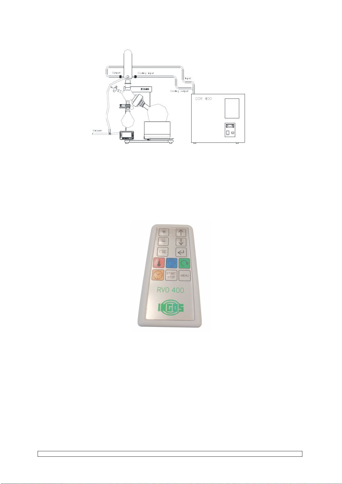
During the evaporation of aggressive substance engage behind the cooler outlet bottle gas
wasching acc. to Drechsler.
Terms of service vacuum pump are in the user manual.
Caution! If you are replacing the round-bottom flask after the vaporized solution has become
thicker, pay particular attention and if it is not possible to remove the flask easily from the cone, carry
out any other handling only after the cooling of the bath.

INGOS Ltd. RVO 400 Page 18
Caution! If you use oil as the filling of the heating bath, the heating bath must be properly dried
before its being filled.
Caution! If you are working with oil heated above 100°C, you must ensure that no water
can enter into the oil. If you are replacing the round-bottom flask, pay particular attention
that no water drops shall enter into the oil. While working, use personal protection
equipment (goggles, gloves, coat and shoes).

INGOS Ltd. RVO 400 Page 19
7. ACCESSORIES AND SPARE PARTS
7.1 Basic accessories (comes with evaporator)
Main inlet cord
Inlet cord Glass assembly
Round bottom flask (1000, 2000 or 4000 ml) NZ29/32
Receiving flask (1000 or 2000 ml) KS 35/20
Suck pipe
Ball adapter
Vertical condenser
Filling pipe with a valve
3 pieces of GL14 connection fitting
Sealing: PTFE sealing (Fig. 3a, pos. 4)
Fixed clip Keyboard
Adaptor Keyboard
Cables 0.4 and 2m
Tubing coupler PA vacuum tubing (100, 110 a 150cm)
7.2 Other accessories
7.2.1 Glass accessories
(fig. 17)
4SKL0021 Evaporating flask 50 ml, joint NZ29/32
4SKL0025 Evaporating flask 100 ml, joint NZ29/32
4SKL0022 Evaporating flask 250 ml, joint NZ29/32
4SKL0023 Evaporating flask 500 ml, joint NZ29/32
4SKL0004 Evaporating flask 1000 ml, joint NZ29/32
4SKL0003 Evaporating flask 2000 ml, joint NZ29/32
4SKL0012 Evaporating flask 4000 ml, joint NZ29/32 (only RVO400)
4SKL0050 Receiving flask 100 ml, joint KS35/20
4SKL0017 Receiving flask 250 ml, joint KS35/20
4SKL0024 Receiving flask 500 ml, joint KS35/20
4SKL0006 Receiving flask 1000 ml, joint KS35/20
4SKL0034 Receiving flask 2000 ml, joint KS35/20
4SKL0005 Vertical condenser
4SKL0033 Diagonal condenser
4SKL0020 Dry ice trap
4SKL0001 Filling pipe with a valve - short
4SKL0002 Filling pipe with a valve - long
4SKL0008 Ball adapter
4SKL0038 Ball adapter for steam temperature sensor
4SKL0040 Steam temperature sensor
4SKL0036 Suck pipe
4SKL0016 Test tube 20 ml, joint NZ14/23
4SKL0009 Flask 100 ml, joint NZ14/23
4SKL0010 Flask 250 ml, joint NZ14/23
4SKL0019 Spider with 3 sleeves NZ14/23 (max. flask 250ml)
4SKL0018 Spider with 5 sleeves NZ14/23 (max. flask 100ml)
4SKL0011 Spider with 6 sleeves NZ14/23 (max. flask 20ml)
4SKL0014 Foam trap NZ29/32 - NZ14/23
4SKL0015 Foam trap NZ29/32 - NZ29/32
4SKL0035 Adapter NZ29/32 - NZ14/23

INGOS Ltd. RVO 400 Page 20
7.2.2 Spare parts, other accessories
RO1520 Protective bath cover plexiglass to 100°C
RO1530 Protective bath cover stainless steel
1TOO0007 Gufero sealing 35/22/10 (Fig.3b)
1TG24524 Flat sealing
1TOO0008 Sealing PTFE(Fig.3a)
RO1080 Fixed clip (for KS32/20)
RO1041 Elastic clip (for NZ14/23)
4SKL0026 Straight fitting GL 14
4SKL0027 Cap nut GL 14
90000013 Tubing coupler
5HAD0003 PA Vacuum tubing
90000036 Vacuum pump low chemical resistant( VM20D recommended)
90000044 Spare diaphragms and sealing for VM20D
Vacuum pump KNF high chemical resistant
3VOD0003 Inlet cord
Fuses5x20mm: T 10 A, T 3.15 A , T 0.5 A
Remote control
Other manuals for RVO 400
1
Table of contents
Other Ingos Laboratory Equipment manuals
Popular Laboratory Equipment manuals by other brands

Metrohm
Metrohm 814 manual

Agilent Technologies
Agilent Technologies 1260Infinity II Bio-inert FractionCollector user manual

Sarstedt
Sarstedt LC 24 instruction manual

Digisol
Digisol DG-PE1148D Quick installation guide

Thermo Scientific
Thermo Scientific TRACE GC Ultra installation guide

CORNING
CORNING LSE 6755 instruction manual