INHECO DWP User manual
Doc ID: 900434-001
March 2018
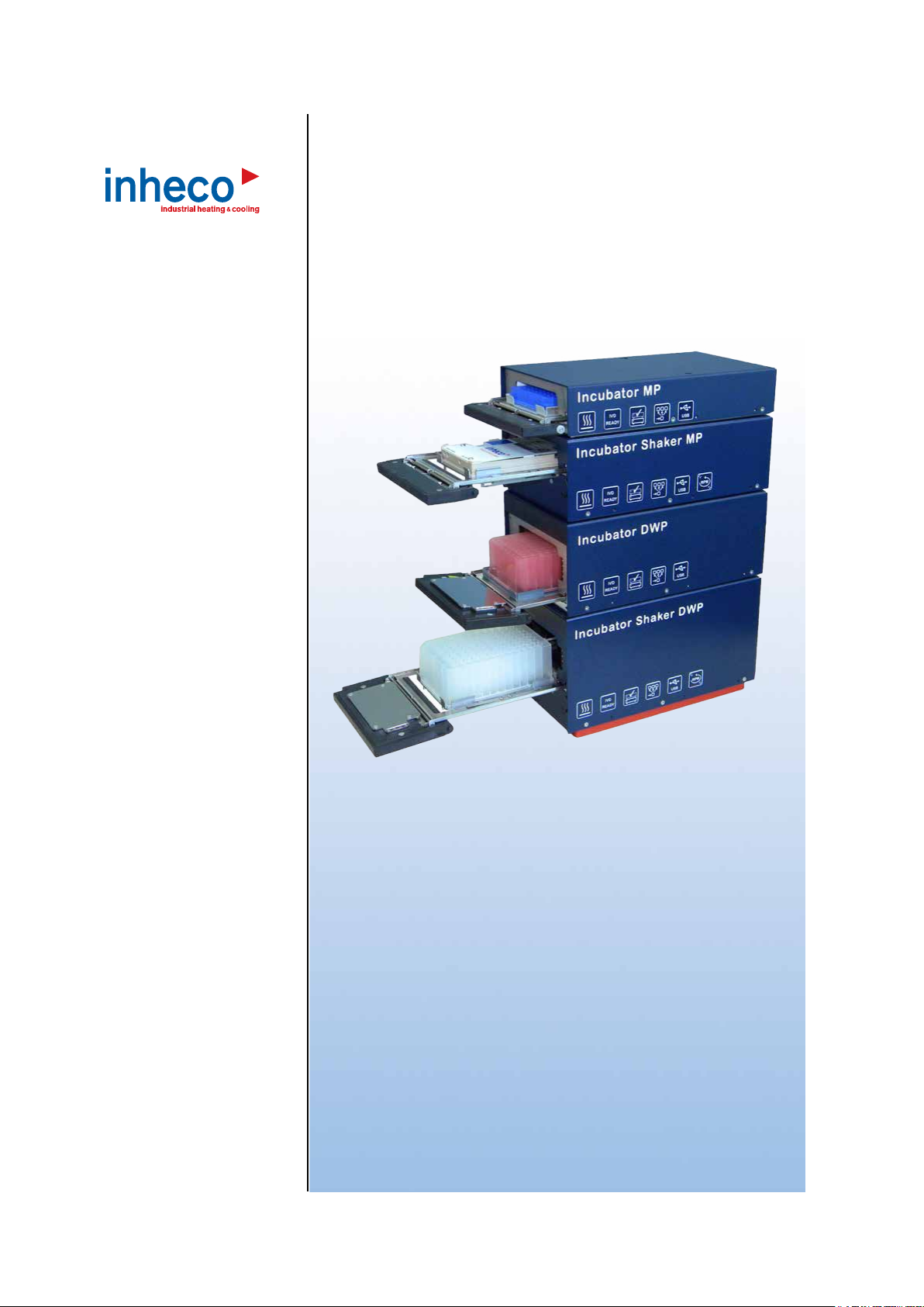
INHECO Single Position Incubators
Incubator MP / DWP
Part No.: 7300003 / 7300006
Incubator Shaker MP/ Shaker DWP
Part No.: 7300013 / 7300009

INHECO 02
Doc ID: 900434-001
March 2018
INHECO Industrial Heating and Cooling GmbH reserves the right to modify their
products for quality improvement. Please note that such modifications may not be
documented in this manual.
This manual and the information herein have been assembled with due diligence.
INHECO GmbH does not assume liability for any misprints or cases of damage resulting
from misprints in this manual. If there are any uncertainties, please feel free to contact
[email protected]. → How to contact INHECO, page 6.
The brand and product names within this manual are registered trademarks and belong
to the respective titleholders.

INHECO 02
Doc ID: 900434-001
March 2018
Table of Contents
Important Notes ......................................................................................... 03
General Information ..................................................................................... 03
Explanation of symbols................................................................................ 04
Abbriviations and Glossary .......................................................................... 04
Warranty ...................................................................................................... 05
How to contact INHECO .............................................................................. 05
Product Description .................................................................................. 06
Intended Use ............................................................................................... 06
Scope of Supply........................................................................................... 07
Functional Elements .................................................................................... 08
Labels .......................................................................................................... 09
Technical Data............................................................................................. 10
Shaker functionality Incubator Shaker MP / DWP ....................................... 12
Thermal functionality Shaker MP / Shaker DWP ......................................... 13
Safety instructions .................................................................................... 14
Product-specic Risks ................................................................................. 14
Technical Alterations ................................................................................... 15
Malfunctions................................................................................................. 15
Hardware installation ................................................................................ 16
Scope of Supply........................................................................................... 16
Initial Operation............................................................................................ 16
Electrical Details General ............................................................................ 18
Adress Switch .............................................................................................. 19
Connecting devices ..................................................................................... 19
Mechanical Integration................................................................................. 21
Labware Use and Detection ........................................................................ 22
Communication with the Incubator.......................................................... 23
Integration in workstation............................................................................. 23
COM port identication ................................................................................ 23
Example conguration of several Incubators to the USB Host PC .............. 25
Operation.................................................................................................... 26
Typical Process Example for integration in robotic systems........................ 26
............................................................................................... 28
Cleaning....................................................................................................... 28
Decontamination.......................................................................................... 28
Servicing ..................................................................................................... 28
Software updates......................................................................................... 28
Calibration and Adjustment.......................................................................... 29
Trouble-Shooting & Support ........................................................................ 29
Return to INHECO only with RMA Number ................................................. 30
Transportation and Storage ......................................................................... 30
Shut Down and Disposal ............................................................................. 30
Assembling the transportation lock.............................................................. 31
Quality......................................................................................................... 32
Final QS Tests ............................................................................................ 32
Calibration and Adjustment.......................................................................... 32
Automatically self test AQS ......................................................................... 32
Failures ....................................................................................................... 33
Drawer failure ............................................................................................... 33
Accessories................................................................................................ 35
Appendix .................................................................................................... 36

INHECO 03
Doc ID: 900434-001
March 2018
1
1.1. General Information
Read the user instructions completely. The manual explains how to handle the Incubator
DWP, Incubator MP, Incubator Shaker DWP and Incubator Shaker MP (Incubator
devices). For the operation of the Incubator devices a third party workstation software is
strongly recommended. → Communication with Incubator devices®, chapter 5
The manual explains how to handle the INHECO stackable devices.
In case the instructions contained in this manual are not followed, injury or product
damage cannot be excluded.
Missing or insufficient knowledge of the manual leads to loss of liability against
INHECOGmbH.
This manual is part of the Incubator devices and must be retained until the unit is
disposed of and must be passed on with the Incubator device when the unit is taken
over by a new user.
The Incubator devices meet the acknowledged rules of technology and comply with
today‘s standards.
Manual instructions must be followed in order to limit the safety risk during operation of
the unit.
Security-related warnings in this manual are classified into three hazard levels:
- The signal word WARNING indicates hazards which – without precautionary
measures – can result in serious injury or even death.
- The signal word CAUTION is given to indicate hazards which – without precautionary
measures – can result in minor to moderate injuries or could disturb the proper
functioning of the unit.
- The signal word NOTE stands for the general precautionary measures that have to
be taken to avoid damaging the device.
- The signal word NOTICE stands for the general measures that help using the device.
Contact INHECO in case there are any uncertainties of how to operate or how to handle
the Incubator devices.
Your opinion about this manual provides us with valuable insights on how we can
improve this document. Please do not hesitate to direct your comments to
[email protected], → How to contact INHECO, page 6

INHECO 04
Doc ID: 900434-001
March 2018
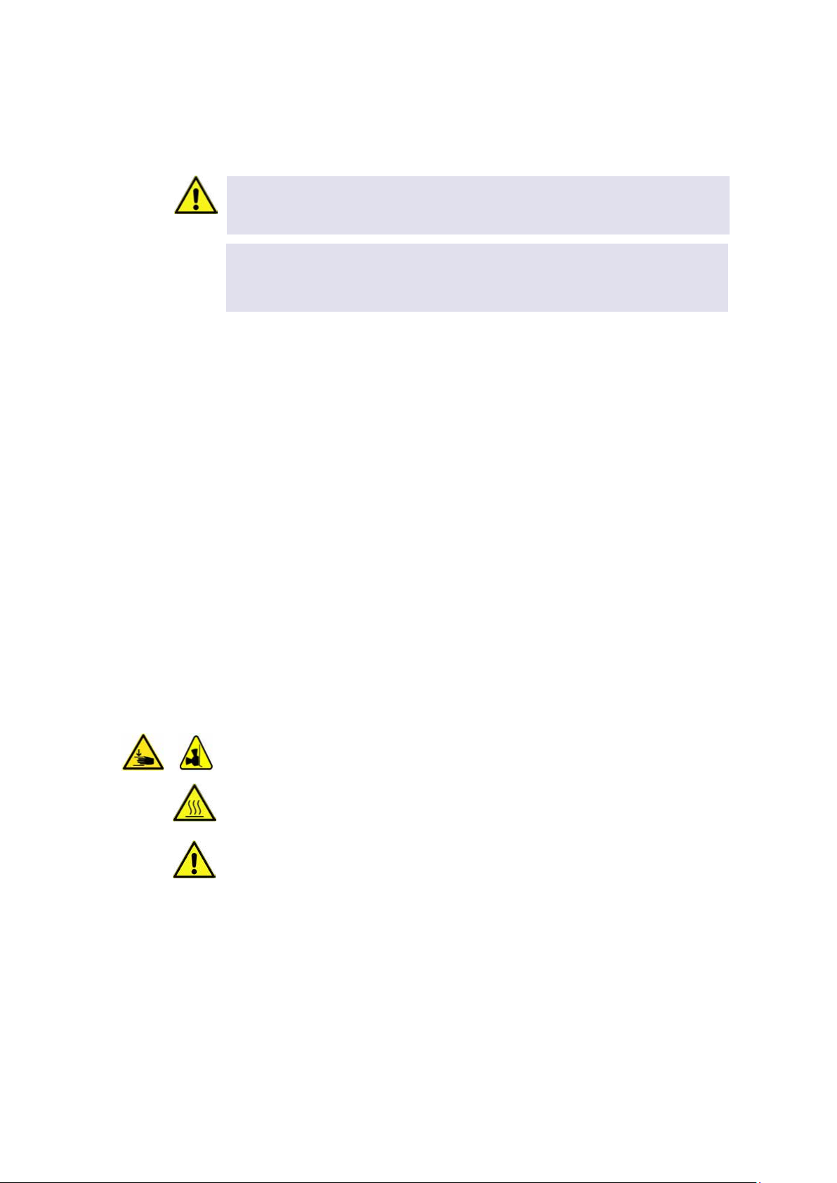
1.2. Explanation of symbols
Symbol Explanation
A possible danger, leading to serious bodily harm is being pointed out to you.
Caution: hot surface
Excenter within the device
Indication for electrostatic discharge (ESD)
·Bullet points indicates an instruction.
-Hyphens refer to enumeration.
→indicates refer to and are mostly an active link
Blue writing indicates a software button
1.3. Abbriviations and Glossary
The document uses the following terms
CC Communication controller
Controller Microprocessor with on chip peripheral
Cyclic Redundany Check
FCS Firmware Command Set
Heater Same as Temperature Controller
IVD (D) In vitro diagnostic (directive)
Micro Plate
Polymerase Chain Reaction
Pulse-Width Modulation
Shaker Controller for shaker regulation
TBC To Be Continued
Temperature
Controller
Controller for heat regulatioin
Universal Serial Bus
CE Conformity Mark
Nationally Recognized Testing Laboratory
Dynamic Link Library
PC Personal Computer
European Union
SBS Society for Biomolecular Screening
DWP Deepwell Plate
IVD In vitro diagnostics
FDA Food and Drug Administration
DIP Dual In line package
N.A. Not Applicable
Room Temperature
wo without
wwith

INHECO 05
Doc ID: 900434-001
March 2018
1.4. Warranty
The warranty period starts on the date of shipment. Any damage caused by operating
the Incubator device outside the specifications and guidelines leads to the loss of
warranty. Broken seals on INHECO devices lead to the loss of warranty as well.
INHECO will only accept parts / devices for return that do not pose a threat to the health
of our staff. In particular, the devices may not have been used in Biosafety Level 3 and 4
environments, or have been exposed to radioactive or radiation materials. → Cleaning
and Decontamination, page 37.
Devices exposed to Biosafety level 3 and 4 Environments are not accepted by INHECO
for return.
1.5. How to contact INHECO
INHECO GmbH
Address Fraunhoferstr. 11
82152 Martinsried
Germany
Telephone - Sales +49 89 899593 120
Telephone - Techhotline +49 89 899593 121
Fax +49 89 899593 499
E-Mail - Sales [email protected]
E-Mail - Technical -Hotline [email protected]
Website www.inheco.com
Technical Support & Trouble Shooting Instructions:
http://www.inheco.com/service/technical-support.html

INHECO 06
Doc ID: 900434-001
March 2018
2
2.1.
INHECO’s Incubators (Incubator MP, Incubator DWP, Incubator Shaker MP and
Incubator Shaker DWP) are automated and compact single incubating positions for the
use in fundamental research, drug discovery, clinical research and diagnostic
applications in automated liquid handling stations.
The incubators can be used as stand-alone devices or stacked to form a tower. The
flexible design of the incubator devices allow even stacking of different devices in one
tower. The unique vibration reduced shaking principle offers free programmable shaking
curves (orbital, linear, eight, elliptic, etc) and amplitudes. The precise automated drawer
system guarantees a direct and easy access by robotic grippers and pipetting heads.
The Incubator devices have a built-in precise temperature and shaker control (only
shaker devices), plate loading sensors, several test routines and an USB interface for
controlling the devices, enabling the use of the Incubator products in FDA, IVD compliant
environments and applications. Software and verification tools are available to form a
complete thermal solution for all kinds of incubation applications.
The Incubator devices are designed specifically for use in Life Science and In Vitro
Diagnostics. The Incubator devices are prepared for easy integration into IVD
applications, but the final IVD validation has to be performed by the first marketer (IVD
application).
When using the devices of the Incubator family in a Biosafety Laboratory Environment,
the user of the device is responsible for labeling the device according to the WHO
Laboratory Biosafety Manual (ISBN 92 4154650 6). The user is furthermore responsible
for operating the devices of the Incubator family depending on the biosafety level
regulations according to the WHO Laboratory Biosafety Manual.
A technical skilled integrator has to install and integrate the Incubator. The Incubator
should be used exclusively by laboratory professionals trained in laboratory techniques
with labautomation systems and having studied the instructions for use of this
instrument.

INHECO 07
Doc ID: 900434-001
March 2018
2.2. Scope of Supply
Before initial operation, make sure that the shipment of your unit and its scope of supply
is complete and no parts are damaged.
In case of parcel or product damages, make photos of the damaged boxes and products
and email them to T[email protected] immediately. Transportation damages must
be reported to INHECO within 7 days of delivery. The following components should be
included in each shipment:
Fig.1: Components
( 1 ) Incubator 1) ( 3 ) 15 - Pole Sub-D-Connector
( 2 ) USB cable ( 4 ) Power cord Europe, UK or US (not scope of supply unless ordered)
( 5 ) Power supply (not scope of supply unless ordered)
1) Image differs depending on which system has been ordered
3
1
2
45

INHECO 08
Doc ID: 900434-001
March 2018
2.3. Functional Elements
Figure 2 introduces the terminology of the Incubator´s functional elements.
Fig.2: Functional elements
( 1 ) Fan ( 4 ) USB Connnector ( 7 ) 15 pole Sub-D-Connector male.
( 2 ) Loading drawer ( 5 ) Address Switch ( 8 ) 15 pole Sub-D-Connector female.
( 3 ) Front door ( 6 ) Power Connector
INHECO 09
Doc ID: 900434-001
March 2018
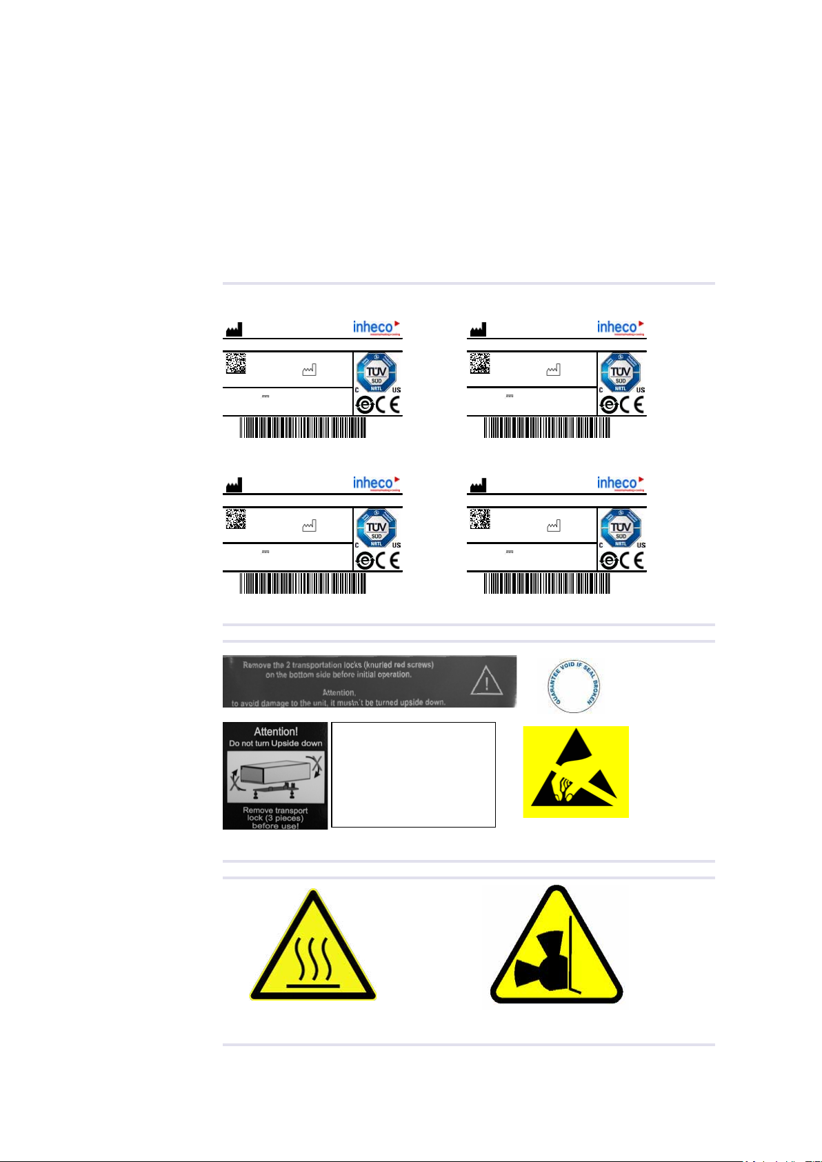
2.4.
The identification label with part number and serial number also contains important
technical indications. The electrical specification on the label must meet your local
situation. The label is placed on the back panel of the Incubator device. The identification
label must not be removed. If it has become illegible or falls off, it has to be replaced by a
new identification label. New labels can be ordered at INHECO. In case the label is
missing and you do not know the part number and serial number, they can also be read
out with the software ( IVDD Incubator software) which can be downloaded from the log
in section of www.inheco.com. → Manual INHECO Incubator Shaker control.
Incubator MP Incubator DWP
1000
INHECO GmbH
82152 Martinsried / Germany
04PN:
SN:
Input: 24V
7300003
Incubator MP
2016-09
Rev.:
30W
Fuse: F3.15A
Incubator Shaker MP Incubator Shaker DWP
Fig.3:
1000
INHECO GmbH
82152 Martinsried / Germany
04PN:
SN:
Input: 24V
7300013
Incubator Shaker MP
2016-09
Rev.:
50W
Fuse: F4.0A
Examples of identication labels
Fig.4: Labels outside device or package
Fig.5: Labels within the device
1000
INHECO GmbH
82152 Martinsried / Germany
05PN:
SN:
Input: 24V
7300006
Incubator DWP
2016-09
Rev.:
45W
Fuse: F3.15A
1000
INHECO GmbH
82152 Martinsried / Germany
05PN:
SN:
Input: 24V
7300009
Incubator Shaker DWP
2016-09
Rev.:
65W
Fuse: F4.0A
Devices are ESD sensible
Transport Lock (3 pieces)!
Always use during
transportation!
Remove transport lock
before use!
Caution Hot Excenter label in shaker
INHECO 10
Doc ID: 900434-001
March 2018
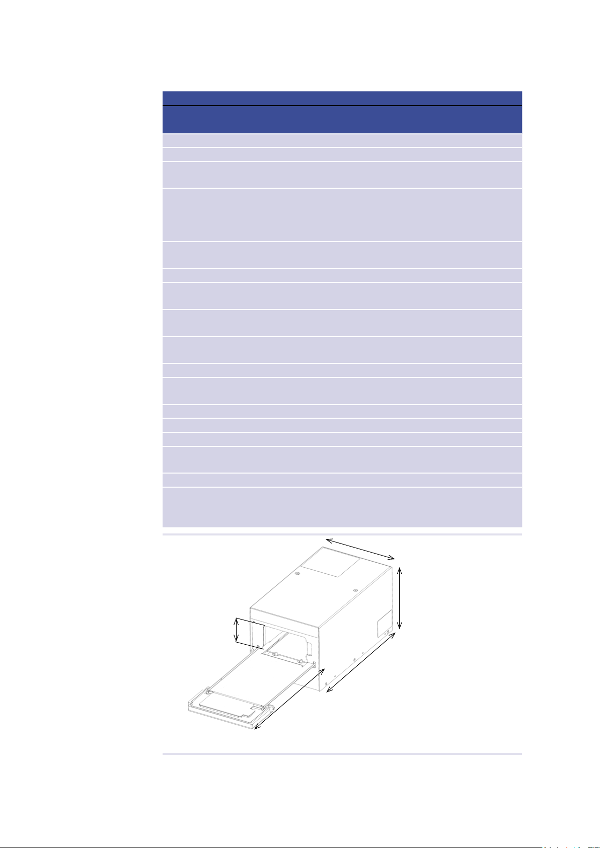
2.5. Technical Data
Technical Data incl. Dimensions
Incubator type MP DWP Shaker
MP
Shaker
DWP
Input voltage 24Vdc
Input power 30W max 45W max 50W max 60W max
Maximum numbers of devices per pow-
er supply (2400121)
6433
Temperature range Room temperature + 5K
up to +80°C (+175°F)
RT+ 5K,
RT + 10K (for shaking
longer than for 1 hour) up
to +80°C (+175°F)
Tolerable realtive humidity ambient 10-80% relative (non condensing)
at +20°C (+68°F) up to +30°C (+86°F)
Maximum load of the shaker platform N.A. 250 g
Shaker frequency range N.A. 6.6 Hz to 30 HZ → 400
rpm to 1800 rpm
Maximum shaking amplitude
(dierence between the maxima)
N.A. 3 mm
Shaking direction N.A. Arbitrary programmable:
e.g. orgital / linear
Dimension in YModule w connector cable 295.5 mm
Dimension in YModule wo connector
cable
268.5 mm
Dimension in XModule 149 mm
Dimension in ZModule wo pin 58 mm 104 mm 88,5 mm 139 mm
Open drawer incl. door YDrawer 193.5 mm 223.5 mm 209 mm 239 mm
Dimension of the thermal chamber in
ZChamber
18 mm 50 mm 18 mm 53 mm
Weigth 2.5 kg 3.4 kg 4.5 kg 5.4 kg
Maximum Number of devices in one
stack due to interaction during shaking
and power limitation of power supply
5432
Fig.6: Dimensions
YDrawer
ZChamber
XModule
ZModule
YModule

INHECO 11
Doc ID: 900434-001
March 2018
Drawer Specications
Accuracy of the end position of the drawer in x,
y and z (drawer open); single unit, all parts at
specied ambient temperature
±0,30 mm
Maximum Drawer load 0,25 kg
Open drawer resistance for a force in Z-axis
without plastic deformation
10 N
Enviromental Conditions
Maximum operation height
Tolarable relative humidity Operation 10-80% relative (non condensing) at
+20°C (+68°F) up to +30°C (+86°F)
Transportation and
storage
-10°C to +60°C [+14°F to +140°F],
non condensing
Temperature Operation +20°C to + 30°C (+68°F to +86°F)
Transportation and
storage
10°C to + 60°C (+14°F) to 140°F),
non condensing

INHECO 12
Doc ID: 900434-001
March 2018
2.6.
Parameter Value
Amplitude range 0.0 – 3.0 mm*
Speed range 6.6 – 30.0 Hz*
Speed precision ±2 Hz
Load 40 – 250g* (weight of plate and liquid and adapter)
Supervision speed and amplitude (closed loop controller)
Shaker movement
North – South (linear)
East – West (linear)
Round (orbital)
“Eight” (this is possible but not recommended because it might damage the
shaker)
Shaker Movement
Amplitude accuracy** ±20% (of the target amplitude)
Phase shift accuracy** ±11°
** validated for the Heating Plate movement / average value over 10 cycles
Single Axis (North – South and East – West) Shaker Load: 100g
Shaker
Speed [Hz]
Shaker amplitude [mm]
Single device
10 X = 1.0 to 2.2
or
Y = 1.0 to 2.2
X = 1,0 to 1.9
or
Y = 1.0 to 1.9
15 X = 1.0 to 2.7
or
Y = 1.0 to 2.7
X = 1.0 to 2.4
or
Y = 1,0 to 2.4
20 X = 1,0 to 1.2
or
Y = 1.0 to 1.2
X = 1.0 to 1.2
or
Y= 1.0 to 1.2
Shaker
Speed [Hz]
Shaker amplitude [mm]
Single device
10 X = 1.0 to 2.2
Y = 1.0 to 2.2
X = 1,0 to 1.9
Y = 1.0 to 1.9
15 X = 1.0 to 2.7
Y = 1.0 to 2.7
X = 1.0 to 2.4
Y = 1.0 to 2.4
20 X = 1.0 to 1.2
Y = 1.0 to 1.2
X = 1.0 to 1.2
Y = 1.0 to 1.2
Shaker
Speed [Hz]
Shaker amplitude [Hz]
Single device Triple Stack
X = 12 /
Y = 24
X = 1.0 to 2.4
Y = 1.0 to 2.4
X = 1.0 to 2.2
Y = 1.0 to 2.2
X = 15 /
Y = 30
X = 1.0
Y = 1.0
X = 1.0
Y = 1.0
* For detailed shaker performance, see chapter below.
X
Y
front
shaking table

INHECO 13
Doc ID: 900434-001
March 2018
2.7.
Parameter Value
Temperature
range
Room Temperature plus 5K to +80°C [+176°F]
Accuracy abso-
lute (@ ambient
temperature
stability ±1K)
The accuracy is dened as the dierence between the target temperature of
the heating plate and the average of the measured temperature on the heating
plate. The heating plate temperature is measured at 5 positions on the heating
plate according to the INHECO measurement head PM-0105. The 5 measure-
ment positions are according to the Plate positions A1, H1, E6, A12 and H12.
Target Temp. Validation Tool
+37°C [+98,6°F] ±1
+60°C [+140°F] ±1.5
+80°C [+176°F]
(temperatures higher than +60°C re-
duces the uniformity over the labware)
±2
Uniformity mea-
sured in well
Uniformity is dened by the maximum dierence between lowest and highest
temperature according to a Greiner 96 Flat Bottom Plate (Postitions A1, A12,
E7, H12)
Target Temp. Validation Tool
+37°C [+98,6°F] ≤1.8
Evaporation in
unsealed Micro
Plates (can be
reduced by using
lid or cover)
Incubator temperature +37°C
[+98,6°F], max. 25% loss of liquid in
4 h, deionized water, room tempe-
rature 24-26°C [75,2-78,8°F], rel.
humidity 40-50%, altitude at 410 m
over Sea level
Incubator temperature +37°C
[+98,6°F], max. 32% loss of liquid in
4 h, deionized water, room tempe-
rature 24-26°C [75,2-78,8°F], rel.
humidity 40-50%, altitude at 410 m
over Sea level
Heatup time
at start tempe-
rature +20°C
[+68°F] with tar-
get temperature
+37°C [+98°F}
max.30 min;
Volume 280µl
per well. *
max.100 min;
Volume 1.5 ml
per well. **
max.30 min;
Volume 280µl
per well. *
max.120 min;
Volume 1.5 ml
per well. **
* The target temperature is reached when all sensors are in the tolerance band of 37°C ±1°C [98,6°F ±3,6°F]
Measured with: 1)
** The target temperature is reached when all sensors are in the tolerance band of 37°C ±1°C [98,6°F ±3,6°F]
Measured with: 1)
INHECO 14
Doc ID: 900434-001
March 2018
3
3.1.
Follow the safety instructions given below in order to avoid danger for user and device.
General
- The Incubator devices ("the unit") hardly require any maintenance, for minor
maintenance interventions refer to → Servicing, page 37 and Quality, page 41.
- The main power connector of the unit must always be accessible to shut down the
system in case of emergency.
- The unit has to be placed in an upright position.
- Standing ground must be solid, even and stable to bear the devices weight.
- Free air supply must be ensured to prevent damage to the . Do not cover the
ventilation openings at the front and rear panel at any time.
- Ensure a minimum of at least 250mm or 10 inches of free space between the
ventilation openings and adjacent devices or walls.
- Do not exceed minimum or maximum ambient temperature and humidity conditions
during operation or storage of the unit → Technical Data, page 11.
- The unit must not be used in environments with risk of explosion
- The unit is for indoor use only.
- The unit must not be used if the Incubator, the power adapter housing or the power
cable show visible signs of damage.
- Make sure that the electrical specifications on the label at the rear panel of the battery
charger meet your local situation.
Crushing Hazard:
- The excenter can possibly pinch your skin when changing its position.
Burning Hazard:
- The Incubator can burn your skin, even after switching off the Incubator it can still be
hot and could seriously burn your skin.
Electrical Shock:
- The unit must not be used if the unit itself or the power cable shows visible signs of
damage.
- You can suffer an electric shock and injuries, if the Incubator is not connected properly
or if you do not disconnect the unit from the wall power outlet before opening the
housing.
- Never connect or remove the power plug with wet hands.
- Make sure that the Incubator does not get in contact with liquids while the unit is
connected to the power outlet.
- Original power cable provided by INHECO has to be used to guarantee safe and
NOTICE
Turning a shaker unit upside down might require a renewal of the shaker drive. Keep the
screws for later transportation purposes.

INHECO 15
Doc ID: 900434-001
March 2018
proper operation.
- The wall power outlet must have a ground earth connection (Safety Class 1).
- Where an ungrounded receptacle is encountered, a qualified electrician must replace
it with a properly (PE) grounded receptacle in accordance with the local electrical
code.
- Make sure that the electrical specification on the identification label at the side panel
meets your local situation. → Labels and Serial Numbers, page 10.
- When using the Incubator devices in a Biosafety Laboratory Environment, the user is
responsible for labeling it according to the WHO Laboratory Biosafety Manual (ISBN
92 4154650 6) and for operating the devices in accordance with the Biosafety Level
Regulations of the WHO Laboratory Biosafety Manual.
ESD Electrostatic discharge
- The Incubator devices are ESD (electrostatic discharge) sensitive devices.
Electrostatic charges as high as 4000V accumulate on the human body can
discharge without detection.
- Although the Incubator devices feature proprietary ESD protection circuitry,
permanent damages may occur to devices subjected to high energy electrostatic
discharge.
3.2. Technical Alterations
- Do not alter the product. Any modification or change which is not approved by
INHECO leads to the loss of warranty. Broken seals on INHECO devices lead to the
loss of warranty as well.
- Use only original parts provided by INHECO. Parts provided by other suppliers can
impair the functionality of the unit.
- Damages due to the use of non-original parts are excluded from INHECO's liability.
3.3.
- In case of a malfunction, switch off and disconnect the Incubator device immediately.
Make sure to inform the authorized person in charge.
- Make sure that the malfunctioning unit is not accidentally re-inalled and used before
the malfunction is eectively eliminated. → Trouble Shooting and Support, page 38.
INHECO 16
Doc ID: 900434-001
March 2018
4
4.1. Scope of Supply
Before initial operation, make sure that the shipment of your unit is complete and neither
packaging nor parts are damaged → Components, chapter 2.2, page 7. Keep original
packaging for future shipments.
The Power Supply and Power Cable are not part of the scope of supply, as for stacked
devices only the master device needs a Power Supply and Cable . They have to be
ordered separately → Chapter 9.
4.2. Initial Operation
A technical skilled integrator has to install and integrate the Incubator.
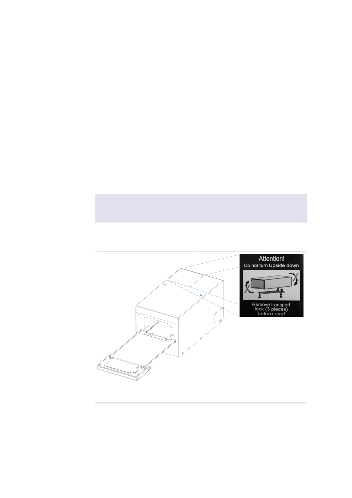
4.2.1. Disassembling the transportation screws
(only for Shaker devices)
After unpacking the Incubator Shaker device, the two red screws (transportation lock) at
the bottom side have to be unscrewed without tilting or turning the device upside down.
Keep the screws and plate for later transportation purposes. Do not dispose the original
package, as it might be needed for further transportation.
NOTE
Turning the unit upside down might require a renewal of the shaker drive calibration.
Keep the screws for later transportation purposes.
A transportation label on the top of the Shaker device is indicating where the
transportation lock is applied and also that you should not turn the device upside down.
Fig.7: Transportation label at the upper side

INHECO 17
Doc ID: 900434-001
March 2018
The transportation lock is a metal plate held with 2 screws at the bottom of the device
Fig.8: Transportation lock at the bottom of the device
• Turn the Incubator Shaker slowly to the left
NOTE!
Cover side in direction of assembler, like in gure 10!
• unscrew the screw just by hand.
Fig.9: Screws screwable without screwdriver
• After the screws are removed the metal plate will have to be actively taken out of the
grid while you till keep the contact at one side.
Fig.10: Loosened metal plate

INHECO 18
Doc ID: 900434-001
March 2018
4.3. Electrical Details General
NOTE
Do not connect the Incubator Devices to the computer before software installation
routine asks you to do so → chapter 5, page 25
• Plug in the power supply and USB cable
Fig.11: Standard connection for one device
The device needs an electrical power supply that provides a stable 24Vdc voltage. The
power consumption for one device is max. 65 Watt. If more devices are stacked, the
power supply must be able to deliver the resulting power consumption. The polarisation
at the power connector at the back side is shown in the following picture. The red circle
shows the “plus-pole” and the black the “minus-pole”. Please contact INHECO →
power supply.
NOTE
Since the USB interface is not optimized for a secure real time data transfer, all
communication is secured by a cyclic checksum (CRC). In case the communication
between the computer and the Incubator Unit often fails due to timeouts, it is likely that it
is due to the computer. Consider the following with regards to communication stability:
- In case you encounter communication instability, verify the communication stability
with dierent computers of dierent congurations.
- Disconnect other devices from the computer which may interfere with the
communication stability.
- De-activate the automated Windows update. For integration purpose, use
INHECO’s DLL and Firmware Command Set → login section www.inheco.com
• check LED Status (optional)
LED status Description
green slow ashing Power is connected
green fast ashing USB connection to PC
green Device has been once initialized*
* If the software is closed and the device still connected with USB and to power the LED remains green. If the
software is restarted the devices have to be initialized again.
INHECO 19
Doc ID: 900434-001
March 2018
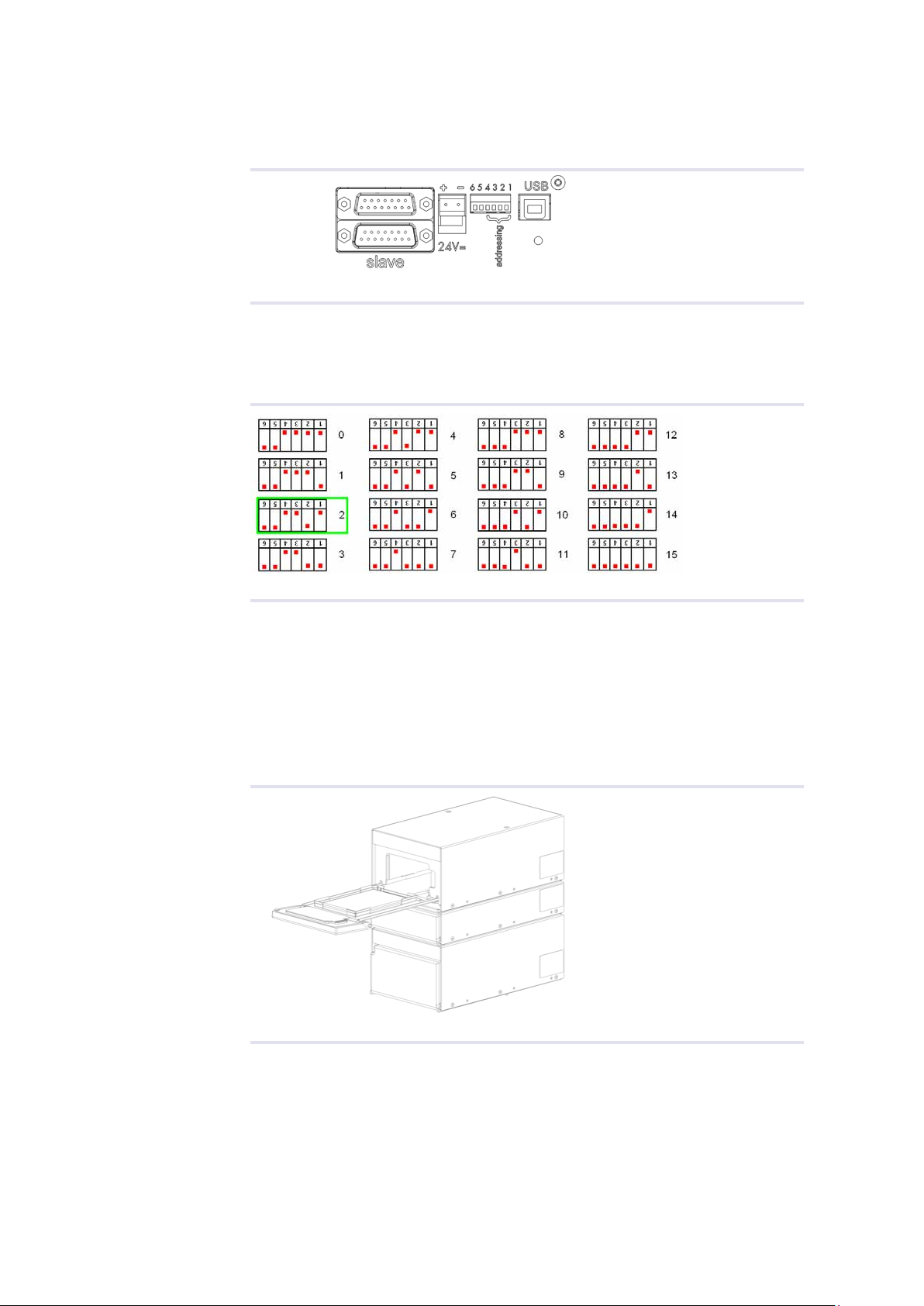
4.4. Adress Switch
A six-pole DIP-Switch can be found at the back side.
Fig.12: Rear side of Incubator showing the Address-Switch
Only the switches 1 to 4 are used for setting the address. These switches are for
identification, if more than one single-device or stack is connected to the PC with USB.
The default address is “2”. The recognition of the device/stack depends on the switches
position as shown in figure 13.
Fig.13: Address-Switch
4.5. Connecting devices
4.5.1. Stackable devices and multiple towers
INHECO’s compact single position Incubators are high performance plug & play
devices for the use on automated robotic platforms or as standalone units. They can
either be used as single devices or stacked in a tower. In addition multiple towers or
single devices can be controlled parallel from one host PC via USB. The combination of
different devices of the Incubator family in one tower is possible.
Fig.14: Example of stacked devices
Two devices are operated with one power supply and controlled via one USB interface,
the 15-pole SUB-D-Connectors on the back side are used for connecting the devices.
The following chapter shows, how the devices have to be connected. → Technical Data
for maximum allowed numbers of instruments, page 11.
This manual suits for next models
3
Table of contents
Other INHECO Accessories manuals

Popular Accessories manuals by other brands

Focusrite
Focusrite Clarett 4Pre USB user guide

promethean
promethean ActivPanel Digital Pen user guide

Microsonic
Microsonic mic+25/IU/TC instruction manual

Grandview
Grandview LF-MixxFII Installation and operation manual

Crucial Audio
Crucial Audio DUB-1 operating instructions

Action
Action S002029 instruction manual


