Thank you very much for using SUNX products. Please read this Instruction Manual carefully and thoroughly for the
correct and optimum use of this product.
Kindly keep this manual in a convenient place for quick reference.
INSTRUCTION MANUAL
CME-LM10(03) No.0014-50V
LM10
Micro Laser Sensor
Photoelectric Displacement Sensor
Safety Precautions
Be sure to follow the precautions below to prevent any injury or accidents from occurring.
Be sure to read this instruction manual before installation, operation, maintenance and inspection.
Before using the product, familiarize yourself with all product information, safety information and cautions.
In this instruction manual, the safety precaution level is classified into 'Warning' or 'Caution'.
٨
٨
When this product is used in applications where serious injury or serious material damage might re-
sult, take safety countermeasures, such as a double-safety mechanism etc.
Do not use this product in a combustive-gas atmosphere. It may cause an explosion.
If the product is mishandled, death or serious injury could result.
If the product is mishandled, serious injury or material damage could result.
WARNING
WARNING
٨
٨
Do not use this product outside the specifications. Abnormal heat or smoking could result.
Never disassemble or modify the product. Electric shock or smoking could result.
CAUTION
CAUTION
The ANR11غhas a 650nm wavelength and a maximum output of 0.4mW making it fall under the
category of products described in Class 1 according to IEC standards' class separation.
Cautionary items for laser beam handling
Be sure to follow the precautions below to prevent any injury or accidents from occurring.
A semiconductor laser is used as the sensor's light source.
٨
٨
٨
These sensors are not equipped with an automatic laser emission halt function when the sensor is disas-
sembled. Therefore, in case of damage or breakage, be sure to notify our office. If having disassembled for
repair purposes, there always exists the danger of being exposed to radiation from the laser
.
Do not use these sensors in a way other than the operation methods described in this manual.
Note㧙Use of controls or adjustments or performance of procedures other than
those specified herein may result in hazardous radiation exposure.
㧙The use of optical instruments with this product will increase eye hazard.
The warning label are attached to the sides of the sensor.
CLASS 1 LASER PRODUCT
LASER APERTURE
The ANR12غhas a 650nm wavelength and a maximum output of 1.6mW making it fall under the
category of products described in Class 2 according to IEC standards' class separation.
٨
٨
٨
٨
٨
Be careful not to look directly at it or looking at its reflection off a mirrored surface.
In order not to have the laser beam go directly into the eyes, position it in a way so that it is higher or lower
than the height of the eyes. Also, point the laser towards a diffuse reflective or an absorptive substance.
These sensors are not equipped with an automatic laser emission halt function when the sensor is disas-
sembled. Therefore, in case of damage or breakage, be sure to notify our office. If having disassembled for
repair purposes, there always exists the danger of being exposed to radiation from the laser.
Do not use these sensors in a way other than the operation methods described in this manual.
Note㧙Use of controls or adjustments or performance of procedures other than
those those specified herein may result in hazardous radiation exposure.
The warning label are attached to the sides of the sensor.
LASER RADIATION
CLASS 2 LASER PRODUCT
(MAXIMUM OUTPUT) 1.6mW
(PULSE DURATION) 15Ǵs
(MEDIUM) SEMICONDUCTOR LASER
(WAVELENGTH) 650nm
DO NOT STARE INTO BEAM
LASER APERTURE
CE MARKING
1
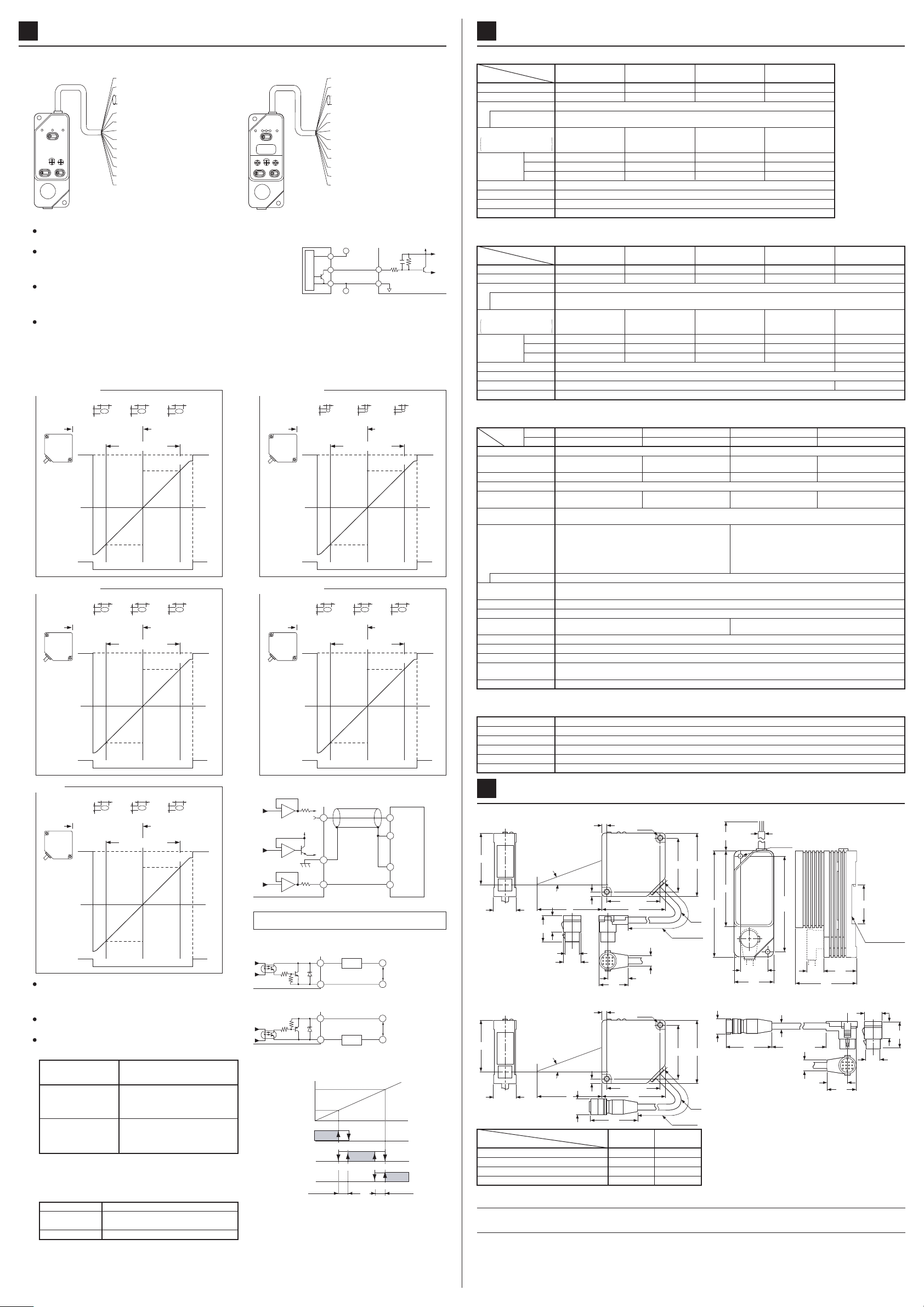
PART DESCRIPTION
2
٨Sensor (ANR11 series)
٨Sensor, Relay cable (ANR12 series)
ٟFor each type
ԘԙLaser emission indicator LED
The LED lights up during laser emission or just before its
emission. To indicate an alarm condition, the LED on the sen-
sor head blinks.
ԚMeasuring range indicator LED
Blinks when a target is within the measurable range. Lights
up when a target is around the measurement center. How-
ever, it may light up or blink even with a significant error in
the measuring range when the alarm is enabled.
ԛAlarm LED
Lights up when measurement is not possible (not enough
light [DARK] or too much light [BRIGHT]).
ԜZero-point adjusting potentiometer
Adjusts the zero-point position to within a r10% of F.S.
Use to make minute adjustment after installing the sensor.
ԝSPEED selection switch
The response speed can be set to one of three settings to
allow adjustment for the target speed. When high response
speed is unnecessary, set to the 10Hz mode.
ԞGAIN selection switch
Under normal conditions, set to AUTO. During edge detec-
tion and other applications where you want to cut out the low
light level areas, set to LOW.
ԟI/O cable
٨Controller
ٟOnly for window comparator type
ԣOperation indicator LED
The LED lights up that corresponds to the comparative
output currently being output.
ԤDisplay / Analog displacement output switch
Switches between the displacement data output and the
comparative value setting output.
ԥLCD display
3-digit display of the displacement data or the upper and
lower limit value.
ԦHIGH limit setting potentiometer
ԧLOW limit setting potentiometer
Sets the comparative value's upper limit (HIGH) and lower
limit (LOW). Set it so that the HIGH value is greater than
the LOW value. By setting the display and analog
displacement output switch to either LOW or HIGH, you can
monitor the set value by display and analog displacement
output. When not set, return the switch to the center
position.
ٟOnly for single comparator type
ԠOperation indicator LED
Lights up when NEAR / DARK ON output is ON.
ԡ
Analog displacement output switch
Switches between the displacement data / intensity data
output and the comparative value setting output.
ԢComparative value setting potentiometer
Sets the comparative value. By setting the analog displace-
ment output switch to the right, the set value can be moni-
tored by the analog displacement output.
Receiver
Emitter Connector to
Controller
ԘԚ
Connector to Controller
Connector for sensor
and expansion cable
ԘԚ
Single comparator type
MICRO LASER
LASER BRT/DRK
ADJ
AUTO
DISPLACE
MENT
LOW
SET
SET
GAIN
SPEED(Hz)
OPERATION
SENSOR LM10
+
-
ԙ
Ԝ
ԝ
ԟ
Ԡ
ԛ
ԡ
Ԣ
Ԟ
Connector
Window comparator type
MICRO LASER
LASER
LOW
SET
LOW HIGH
HIGH
SET
BRT/DRK
ADJ
AUTO
DISPLACEMENT
LOW
HIGHLOW
V
GAIN
SPEED(Hz)
SENSOR LM10
+
-
ԧ
ԣ
Ԥ
ԥ
Ԧ
CAUTIONS DURING SETTING
3
٨
Procedure for setting the sensor head
While watching the measuring range indicator LED,
set the sensor head so that the distance to the sub-
ject body is within the measuring range.
It may light up or blink even with a significant error in
the measuring range when the alarm is enabled.
Range indicator LED
Outside the meas-
urable range
OFF OFFBlink BlinkON
Center
Measurable range
Outside the meas-
urable range
Be careful of the sensor head's orientation during mounting. When the subject body moves as shown below, er-
rors will develop depending on the orientation of the sensor head. In order to minimize these errors, be sure to
mount the sensor head in the correct orientation.
Confirm the mutual interference area when using sensors side
by side.
cba
Model No. a b c
ANR1150
ANR1151
ANR1182
ANR1115
ANR1250
ANR1251
ANR1282
ANR1215
ANR1226
40 20 70
50 60 110
80 100 150
50 40 90
80 80 130
120 140 190
210 350 400
(Unit: mm)
٨
Mounting the sensor head
Using two mounting holes, firmly mount the sensor head so that the sensor head's front surface is parallel to
the target. Do not tighten the installation screws to a torque over 2N䊶m
Glass is used at the sensor head's light emitting and light receiving surfaces and, therefore, never subject it to impacts of any kind. Al-
so, be very careful not to allow oils, finger prints, or other substances that may refract the light, to get on the glass during mounting.
If light reflected off the target is then reflected off nearby objects or walls and then received by the sensor head,
the sensor head reading will be adversely affected. To prevent this, either further separate the sensor head or
apply a black delustering paint to prevent the unwanted reflection of light.
٨
Mounting the controller
When mounting more than one controllers in a row, maintain at least 10m between each unit. Also, when
mounting the controller inside control panels or areas where the air is not properly ventilated, the controller will
cause the ambient temperature to rise. In these cases, ensure cooling facilities.
عEccentricity measurement عStep measurement ع
Extremely different adjacent color or materials
Good
Good Good
Not good
Not good Not good
Lock release
button
٨
Wiring
Perform all wiring by faithfully following the input and output circuit explanations
and documents that came with the instrument. Also, to protect the inner circui-
try, arrange the lead wire that is not interconnected in a way so that it does not
come into contact with other lead wires.
When mounting or removing a connector, always first turn off the controller and
then begin operations.
All connectors are of the lock-on type. When connecting a connector, be sure to
securely insert it until it locks into place. When removing a connector, first press
in the lock release button on the connector side and then remove the connector.
After removing a connector, do not touch the terminals located inside.
R20mm or more
٨
Cable
When the sensor head and controller are fixed and cables connected, do
not subject the cables to a pull of more than 29.4N. Have no bends in the
cables with a radius of less than 20mm. Also, do not bend a sensor head's
cable near where the cable is attached to the sensor head.
When the sensor head is to be moved while in use, do not have it so that
the sensor head's cable becomes bent. If the location is such that it cannot
be helped, we recommend purchasing the appropriate length extension
cable. (ANR12غ)
CAUTIONS
4
٨
Insulation resistance and voltage withstandability
Do not perform insulation resistance or withstand voltage tests between the connector's metal portion and input / outputs.
٨
Noise precautions
The connector's metal portion is internally connected to the analog output GND. In order to prevent affects from
noise or damage to the internal circuits, be sure
Ground the metal case of the sensor head to the frame ground (F.G.) of an equipment.
to insulate the metal portion with electrical tape or other means.
Mount the unit as far away as possible from high voltage lines, power lines, or devices that generate large switch-
ing surges.
Separate the sensor head cable wiring, high voltage circuit, and power circuit.
If there is much noise on the power supply, it will affect the analog output. In such cases, use a noise filter or
noise cut transformer.
٨
Operating environment
Use in an ambient temperature between 0 to +50. Store in a location where the temperature stays between
-20 to +70.
Use in an ambient humidity between 35 to 85% RH. Avoid use in locations with drastic humidity changes which
cause condensation.
Use in locations where the illuminance from incandescent lamps received at the light receiving surface is below
2,500 lx (ANR11غCPFANR1226), or below 3,000lx (ANR1250,
ANR1251, ANR1282, ANR1215).
Also, locate the unit so that sunlight, does not directly hit the beam-receiving part.
When exceptional accuracy is required, mount a shielding plate or other type of shading mechanism.
The power supply voltage should be between 85 to 110% of the rated voltage.
Since the internal circuits may become damaged if an external surge voltage exceeds 500V [r(1.250)Ǵs
unipolar full-wave voltage], always use a surge absorber or surge absorbing element.
Keep the sensor head beam-emitting part and beam-receiving part surface clean and free of moisture, oil, fin-
ger prints, and other light refracting substances, and free of dust, dirt, and other light blocking substances.
When cleaning the glass surfaces, wipe with a soft cloth or lens cleaning paper.
Although the sensor head is of water proof construction, it does not mean that measurements can be taken un-
derwater or in the rain. Moreover, the connectors are not watertight.
Do not use the unit in locations with flammable or corrosive gases, locations with excessive dust, locations
splashed by water, or locations subjected to vibrations or excessive shocks.
Since the controller contains molded resins, do not use in environments that contain, or where contact with,
benzene, thinners, alcohols and other organic solvents; and ammonia, caustic sodas, and other alkaline sub-
stances is possible.
٨
Warm-up time
Allow at least 30 minutes, after turning on the unit, for the unit to properly warm up.
٨
Power supply
Select a power supply with a ripple voltage below 0.5V (P-P) and a current capacity above 0.3A.
In order to avoid high-frequency noises when using a commercially available switching regulator, be sure to
ground the frame ground (F.G.) terminal.
When using a power supply that uses a transformer, be sure to use an insulated transformer. When using an
autotransformer (single-wound transformer), it is possible to damage this unit or the power supply.
Do not turn the power on again within 10 sec.after turning the power off.
٨
٨
Never use this product as a sensing device for personnel protection.
In case of using sensing devices for personnel protection, use products which meet laws and standards,
such as OSHA, ANSI or IEC etc., for personnel protection applicable in each region or country.
WARNING
٨This product has been developed / produced for industrial use only.
٨The models listed under ' SPECIFICATIONS' come with CE Marking.
As for all other models, please contact our office.
6
In case of using this product as a CE marking conformity product, cable extension of the power wire and I/O wire
must be wthin 30m.
Ramco Innovations
800
280-6933 www.SunxSensors.com