INHECO Thermoshake User manual
Doc ID: 900113-003
July 2020
INHECO Heat, Shake & Cool
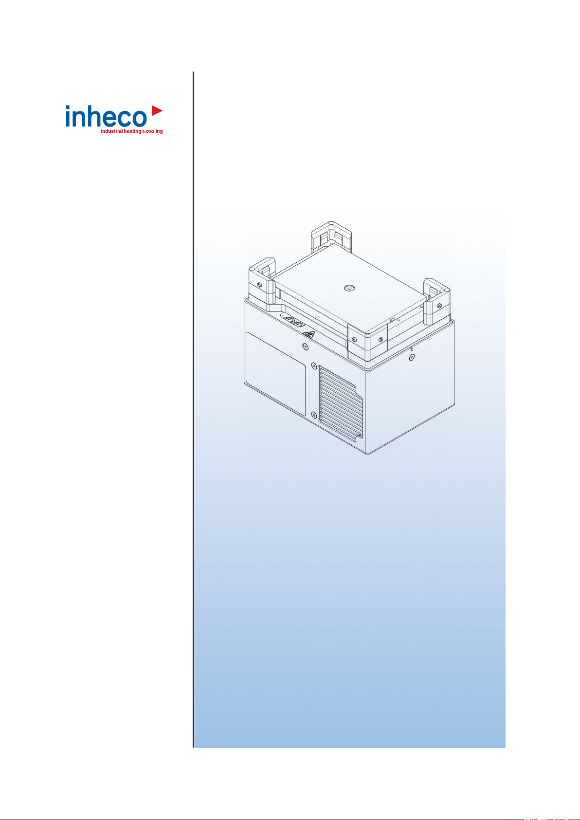
Thermoshake
Part No.: 7100144 / 7100146
► User´s Manual

INHECO 2
Doc ID: 900113-003
July 2020
INHECO Industrial Heating and Cooling GmbH reserves the right to modify their
products for quality improvement. Please note that such modifications may not be
documented in this manual.
This manual and the information herein have been assembled with due diligence.
INHECO GmbH does not assume liability for any misprints or cases of damage resulting
from misprints in this manual. If there are any uncertainties, please feel free to contact
[email protected]. → How to contact INHECO, page 6.
The brand and product names within this manual are registered trademarks and belong
to the respective titleholders.

INHECO 03
Doc ID: 900113-003
July 2020
Table of Contents
Important Notes ......................................................................................... 04
General Information ..................................................................................... 04
Explanation of Symbols ............................................................................... 04
Abbreviations and Glossary ........................................................................ 05
Warranty ...................................................................................................... 05
How to contact INHECO .............................................................................. 06
Product Description .................................................................................. 06
Intended Use ............................................................................................... 06
Scope of Supply........................................................................................... 07
Labels .......................................................................................................... 08
Technical Data............................................................................................. 09
Safety Instructions .................................................................................... 10
Product-specic Risks ................................................................................. 10
Technical Alterations ................................................................................... 11
Malfunctions................................................................................................. 11
Hardware Installation ................................................................................ 12
Scope of Supply........................................................................................... 12
Initial Operation............................................................................................ 12
Programming the Movement Pattern........................................................... 13
Fixation of Disposables (Tubes, Reservoirs, Plates)............................................... 13
Removal of Positioning Brackets ................................................................. 14
Installation of Adapter Plates (Inserts, Nests).............................................. 15
Mechanical Integration................................................................................. 16
Software Installation.................................................................................. 17
Daily Usage ................................................................................................ 17
Safety Instructions for Operation ................................................................. 17
Maintenance ............................................................................................... 18
Software Updates ........................................................................................ 18
Trouble-Shooting & Support ........................................................................ 18
Maintenance (Relling of Cooling Liquid Reservoir).................................... 20
Service for pump...........................................................................................24
Cleaning....................................................................................................... 25
Decontamination.......................................................................................... 25
Calibration / Verication............................................................................... 25
Return for Repair only with RMA Number ................................................... 26
Transportation and Storage ......................................................................... 26
Shut Down and Disposal ............................................................................. 26
Accessories................................................................................................ 27
Multi TEC Control (MTC) / Single TEC Control (STC)................................. 27
Black Slot Module ........................................................................................ 27
Thermal Adapter for Temperature Transfer................................................. 27
Miscellaneous .............................................................................................. 27
Appendix .................................................................................................... 28

INHECO 04
Doc ID: 900113-003
July 2020
1 IMPORTANT NOTES
1.1. General Information
Read the user instructions completely. The manual explains how to operate and handle
the Thermoshake devices: Thermoshake and Thermoshake RM. In case these manual
instructions are not followed, injury or product damage cannot be excluded.
Missing or insufficient knowledge of the manual leads to loss of liability against
INHECO GmbH.
This manual is part of the Thermoshake devices and must be retained until the device is
disposed of and must be passed on with the Thermoshake when the device is taken
over by a new user.
The Thermoshake devices meet the acknowledged rules of technology and comply with
today‘s standards.
Manual instructions must be followed in order to ensure safe handling of the device.
Security-related warnings in this manual are classified into three hazard levels:
- The signal word WARNING indicates hazards which – without precautionary
measures – can result in serious injury or even death.
- The signal word CAUTION indicates hazards which – without precautionary
measures – can result in minor to moderate injuries
- The signal word NOTE stands for the general precautionary measures that have to
be taken to avoid damaging the device when using it.
- The signal word NOTICE stands for the general measures that help using the device.
Contact INHECO in case there are any uncertainties of how to operate or how to handle
the Thermoshake device.
Your opinion about this manual provides us with valuable insights on how we can
improve this document. Please do not hesitate to direct your comments to
[email protected], → How to contact INHECO, page 6.
1.2. Explanation of Symbols
Symbol Explanation
Potential danger of serious injury or death →
signal word WARNINg or CAUTION indicate the severity.
Caution: Potential danger of hot surface.
·Bullet points indicate steps of instructions.
-Hyphens refer to enumerations.
→Arrows indicate: “refer to” and are mostly an active link

INHECO 05
Doc ID: 900113-003
July 2020
1.3. Abbreviations and Glossary
The following acronyms and items are used in this document
°C Degree Celsius
°F Degree Fahrenheit
mm Millimeter
in Inch
Hz Hertz [1/s]
KKelvin
kg Kilogram
lbs Pounds
dB(A) Decibel
RH relative humidity
TEC Thermo- Electric- Cooler (Thermoelectric Module)
Vdc Voltage direct current
Adc Ampere direct current
WWatt
rpm revolutions per minute
IVD In Vitro Diagnostic
FDA Food and Drug Administration
MTC Multi TEC Control controls up to 6 INHECO devices individually
STC Single TEC Control controls 1 INHECO device
Oset The dierence between the set temperature and actual value once the
temperature is stable
PT100 PT100 is a Resistive-Temperature-Detector (RTD). This sensor increases its
resistance with increasing temperature.
Calibration Calibration is the validation of specic measurement techniques and
equipment. At the simplest level, calibration is a comparison between
measurements - one of known magnitude or correctness - made or set with
one device and another measurement made in as similar a way as possible
with a second device.
1.4. Warranty
The warranty period starts on the date of shipment. Any damage caused by operating
the Thermoshakes outside the specifications and guidelines leads to the loss of
warranty. Broken seals on INHECO devices lead to the loss of warranty as well.
INHECO will only accept parts / devices for return that do not pose a threat to the health
of our staff. In particular, the devices may not have been used in Biosafety Level 3 and 4
environments, or have been exposed to radioactive or radiation materials. → Cleaning
and Decontamination, page 25.
Devices exposed to Biosafety Level 3 and 4 Environments are not accepted by
INHECO for return.

INHECO 06
Doc ID: 900113-003
July 2020
1.5. How to contact INHECO
INHECO GmbH
Address Fraunhoferstr. 11
82152 Martinsried
Germany
Telephone - Sales +49 89 899593 120
Telephone - Techhotline +49 89 899593 121
Fax +49 89 899593 149
E-Mail - Sales [email protected]
E-Mail - Technical -Hotline [email protected]
Website www.inheco.com
Technical Support & Trouble Shooting Instructions:
http://www.inheco.com/service/technical-support.html
2 PRODUCT DESCRIPTION
2.1. Intended Use
The Thermoshake is one of the most compact heated and cooled shaking positions for
a wide range of standard ANSI/SLAS (formerly SBS) plates and tubes. The
Thermoshake can be placed on the deck of liquid handling systems with the lowest
possible usage of space. It combines excellent control of temperature and fluid mixing.
The cooling function offers the unique possibility to stop reactions quickly by reducing the
temperature of the liquid samples. Shaking curves are linear and orbital.
The Thermoshake devices can be operated with two types of precise temperature/rpm
controllers with integrated power supply (MTC or STC). The units are heating/cooling
devices with CE and UL certification. They are mainly used on robotic platforms and
systems in LabAutomation.
The Thermoshake is designed specifically for use in Life Science. The Thermoshake is
prepared for easy integration into IVD applications, but the final IVD validation has to be
performed by the first marketer (IVD application).
When using the Thermoshake devices in a Biosafety Laboratory Environment, the user
is responsible for labeling the devices according to the WHO Laboratory Biosafety
Manual (ISBN 92 4154650 6) and for operating the devices according to this Biosafety
Manual.
The Thermoshake must be used exclusively by laboratory professionals trained in
laboratory techniques with labautomation systems and having studied the instructions
for use of this instrument as well as the instructions of the workstation the device is used
in.
INHECO 07
Doc ID: 900113-003
July 2020
2.2. Scope of Supply
Before initial operation, make sure that the shipment of your unit and its scope of supply
is complete and no parts are damaged.
In case of parcel or product damages, make photos of the damaged boxes and products
must be reported to INHECO within 7 days of delivery. The following components should
be included in each shipment:
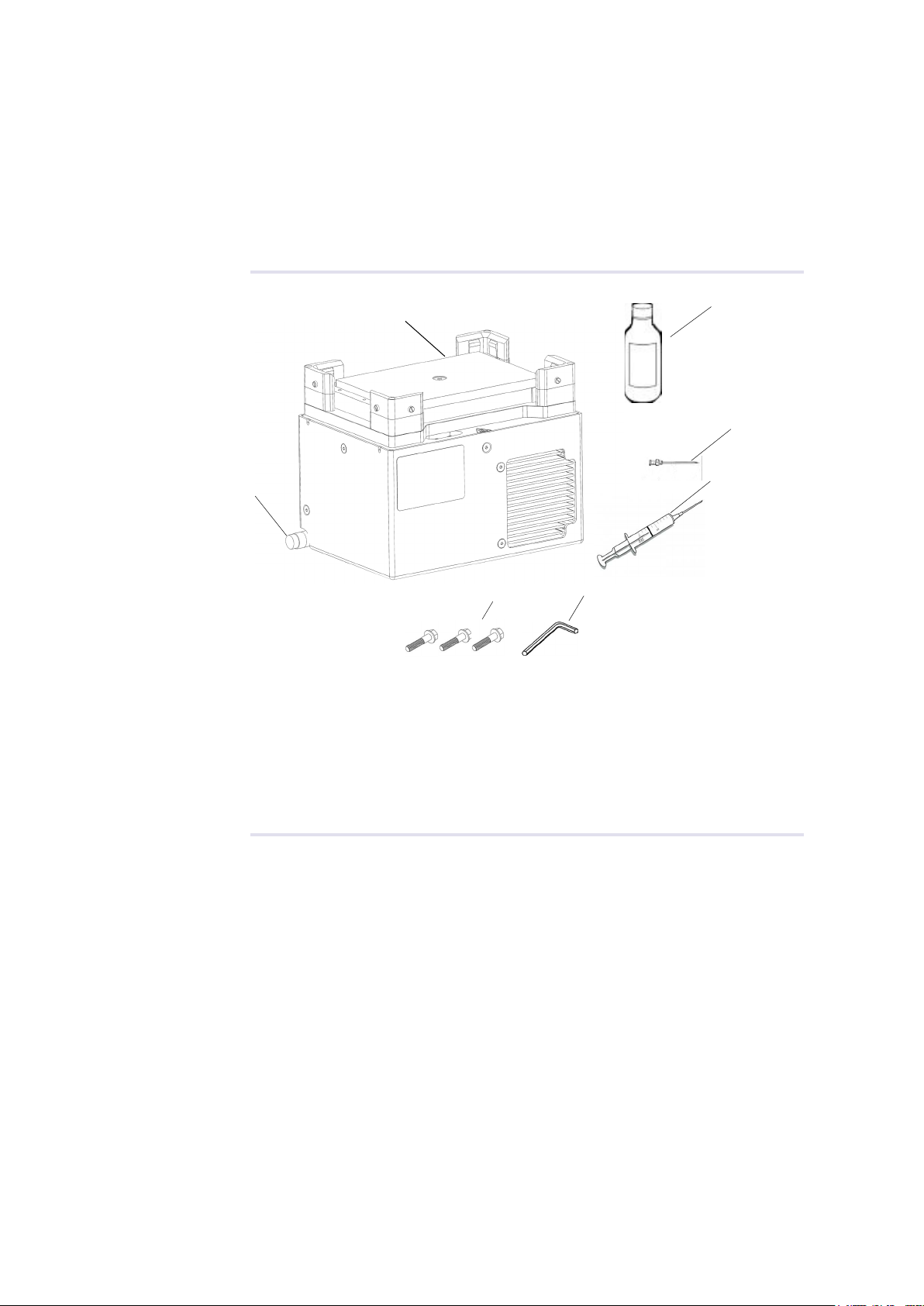
Fig.1: Scope of Supply
( 1 ) Thermoshake incl. Sub-D-Connector Cable *
( 2 ) Syringe to refill the cooling liquid
( 3 ) Syringe needle to refill the cooling fluid
( 4 ) Cooling fluid
( 5 ) Socket wrench for filling nozzle of the cooling liquid reservoir
( 6 ) 3 allen screws to fix thermal adapters
* image may vary depending on what Thermoshake is ordered.
The Sub-D-Connector Cable is already connected with the Thermoshake and it also
needs to be conntected to the Black Slot Module installed inside the TEC Control Unit
(MTC or STC). → Initial Operation, page 12.
6
1
2
5
3
4
Cable with Sub-D-Connector
INHECO 08
Doc ID: 900113-003
July 2020
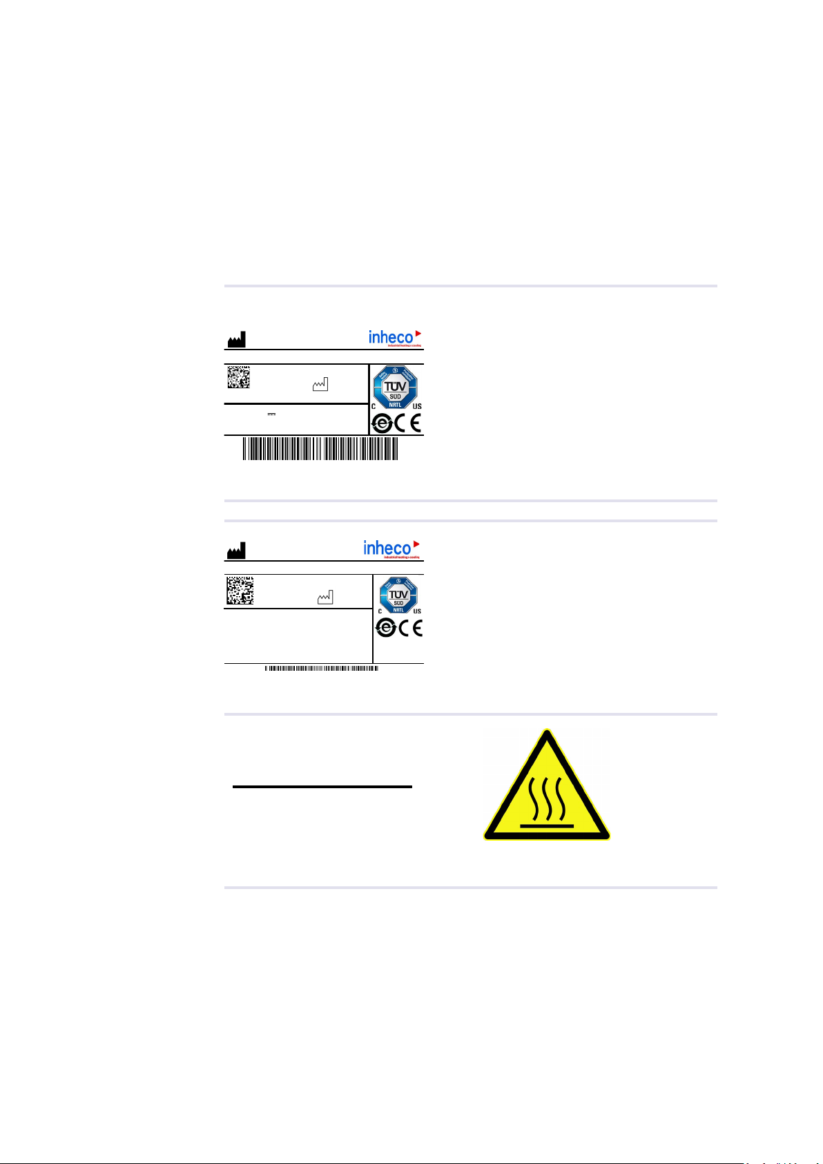
2.3. Labels
The identification label with part number and serial number also contains important
technical indications. The electrical specification on the label must meet your local
situation. The label is placed on the side of the device. The identification label must not
be removed. If it has become illegible or falls off, it has to be replaced by a new
identification label. New labels can be ordered at INHECO. In case the label is missing
and you do not know the part number and serial number, they can also be read out with
the software (MTC/STC Demo Tool) which can be downloaded from INHECO´ login
section on www.inheco.com. → Trouble Shooting & Support, page 18f.
Thermoshake
1000
INHECO GmbH
82152 Martinsried / Germany
02PN:
SN:
Input: 24V Imax: 5,3A
7100146-A
Thermoshake
2016-09
Rev.:
Fig.2: Product labels on the device
INHECO GmbH
82152 Martinsried / Germany
1000
02PN:
SN:
7100146-A
Thermoshake
2016-09
Rev.:
Storage and transportation conditions:
-10°C to +60°C [+14.0°F to +140°F],
10% to 80% RH, non condensing
Fig.3: Shipment labels on the package
Fig.4:
In case of an empty reservoir
refill with
32ml
INHECO Cooling Liquid only!
CAUTION!
Overfilling may cause
malfunction of the liquid circuit!
Other lables on the product
Caution Hot
INHECO 09
Doc ID: 900113-003
July 2020
2.4. Technical Data
Technical Data incl. Dimensions
Thermoshake type Thermoshake Thermoshake RM
Outer dimensions
height
p/n 7100146
118 mm
[4.685 in]
p/n 7100144
116 mm
[4.567 in]
Length x width 147 mm x 104 mm
[5.787 in x 4.095 in]
Input voltage / max. current 24Vdc / 5.3Adc
Temperature range +4°C to +70°C
[+39.2°F to +158°F]
Maximum ∆T (=Tambient- Ttarget)25°C (cooling mode only)
[77°F]
Noise Max. 42dB(A)
Maximum load 1.0 kg
(→ also performance curve)
Shaker frequency
weight reduce the max. speed
100 to 2000 rpm
(→ also performance curve)
Shaking amplitude 2 mm [0.07874 in]
Shaking pattern Orbital, linear (diagonal, lengthways, sideways)
Protection Category IP 22
Weight including cables 3.5 kg [7.7 lbs]
Enviromental Conditions
Tolarable relative humidity Operation 10-80% RH (non condensing) at
+20°C up to +30°C [+68°F to + 86°F]
Transportation and
storage
10-80% RH (non condensing) at
+20°C up to +30°C [+68°F to + 86°F]
Temperature Operation +15°C to +32°C [+59°F to 90°F]
Transportation and
storage
-10°C to + 60°C [+14°F to 140°F], non
condensing
* Condensate can prevent the Thermoshake from operating properly and can damage the Thermoshake.
Condensate should be eliminated on a daily basis or more often, for example by heating cycles in between
cooling cycles.
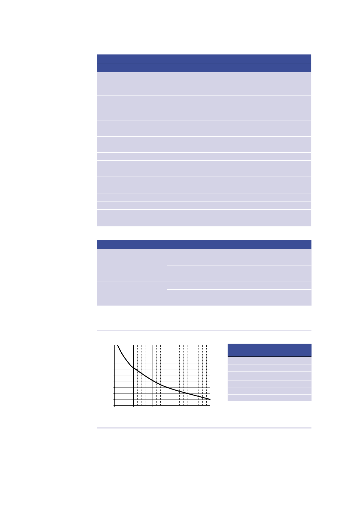
Fig.5:
Performance Thermoshake
Picture 1: Performance characteristic for the orbital shaking mode
Table 1: Movement shape and max. shaking frequency
Movement shape
Max. shaking frequency with
microplate 96 (or load of 82g)
n,w,s,e
1700 rpm
n,e,s,w
1700 rpm
nw, se
700 rpm
ne, sw
700 rpm
n,s,
650 rpm
e, w
400 rpm
1000
1100
1200
1300
1400
1500
1600
1700
1800
1900
2000
0100 200 300 400 500
max. rpm [1/min]
load [g]
orbital shaking maximum speed at different loads
Performance curve
Movement
shape
Max. shaking frequency with
microplate 96 ( or load of 82g)
n,w,s,e (orbital) 1700 rpm
n,e,s,w (orbital) 1700 rpm
nw, se (diagonal) 700 rpm
ne, sw (diagonal) 700 rpm
n, s (sideways) 650 rpm
e, w (lengthways) 400 rpm
INHECO 10
Doc ID: 900113-003
July 2020
3 SAFETY INSTRUCTIONS
3.1. Product-specic Risks
WARNING
Follow the safety instructions given below in order to avoid danger for user and device.
General
- The Thermoshake device (“the device”) needs maintenance on a regular basis
regarding cooling liquid, → Maintenance (Relling of Cooling Liquid Reservoir),
page 20ff and regarding the pump →
- The device has to be placed in an upright position. On non-observance, it will
eventually overheat, causing the temperature fuse to blow.
- The main power switch of the TEC Control Unit must always be accessible.
- Free air supply must be ensured to prevent damage to the device. Do not cover the
ventilation openings at the front and rear panel at any time. Ensure a minimum of at
least 30 mm (1.2 inch) of free space between the ventilation openings at the front and
at the back and adjacent devices or walls.
- Ensure that there is no other device installed next to the device increasing the inletair
temperature for the device above the specified temperatures. In case of doubt, please
contact INHECO for further analysis.
- Do not insert any parts into the ventilation inlet or outlet.
- Do not exceed minimum or maximum ambient temperature and humidity conditions
during operation or storage of the device → Technical Data, page 9.
- The device must not be used in environments with risk of explosion.
- The device is for indoor use only.
Burning Hazard:
- Devices can burn your skin. Even after switching off the TEC Control Unit, the
connected devices can still be hot and could seriously burn your skin as the material‘s
temperature can reach up to +70°C [+158°F]! It takes a while to cool down after the
device has been used.
Electrical Shock:
- The device must not be used if the device itself or the power cable shows visible
signs of damage.
- You can suffer an electric shock and injuries, if the Thermoshake is not connected
properly or if you do not disconnect the device from the TEC Control Unit outlet before
opening the housing.
- Never connect or remove the power plug of the TEC Control Unit with wet hands.
- Original power cable for the TEC Control Unit provided by INHECO has to be used to
guarantee safe and proper operation.
- The wall power outlet must have a ground earth connection (Safety Class 1).
- Where an ungrounded receptacle is encountered, a qualified electrician must replace
it with a properly (PE) grounded receptacle in accordance with the local electrical
code.
- Make sure that the electrical specification on the identification label at the side panel
meets your local situation. → Labels, page 8.

INHECO 11
Doc ID: 900113-003
July 2020
Biosafety Laboratory Environment
- When using the devices in a Biosafety Laboratory Environment, the user is
responsible for labeling the devices according to the WHO Laboratory Biosafety
Manual (ISBN 92 4154650 6) and for operating the devices in accordance to this
WHO Laboratory Biosafety Manual.
3.2. Technical Alterations
- Do not alter the product. Any modification or change which is not approved by
INHECO leads to the loss of warranty. Broken seals on INHECO devices lead to the
loss of warranty as well.
- Use only original parts provided by INHECO. Parts provided by other suppliers can
impair the functionality of the unit.
- Damages due to the use of non-original parts are excluded from INHECO's liability.
3.3. Malfunctions
- In case of a malfunction, switch off and disconnect the device immediately. Make sure
to inform the authorized person in charge.
- Make sure that the malfunctioning unit is not accidentally re-inalled and used before
the malfunction is eectively eliminated. → Trouble Shooting and Support, page 18.
INHECO 12
Doc ID: 900113-003
July 2020
4 HARDWARE INSTALLATION
4.1. Scope of Supply
Before initial operation, make sure that the shipment of your unit is complete and neither
packaging nor parts are damaged → Scope of Supply, chapter 2.2.
4.2. Initial Operation
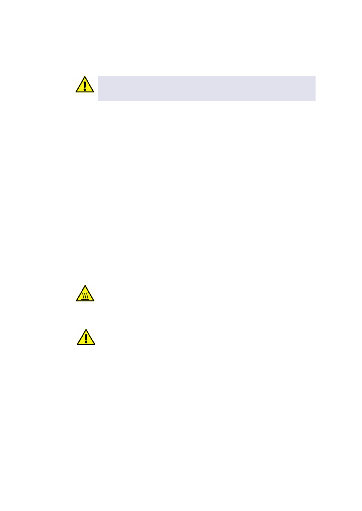
4.2.1. How to connect device to the MTC / STC
In order to connect an INHECO heating/cooling/shaking device, the TEC Control Unit
has to be equipped with the corresponding Slot Module. There are blue, black, and red
Slot Modules available. The following table shows the appropriate Slot Module for each
heating/cooling/shaking device.
Product Color Article No. Heating/cooling/shaking Unit
Blue Slot Module blue 2400128 CPAC
Black Slot Module black 2400125 CPAC HT 2-Tec, HeatPAC, Heated Lid,
Teleshake 95, Thermoshake,
Yellow Slot Module yellow 2400211 Thermoshake AC, Thermoshake AC
180, Teleshake AC, Teleshake 95 AC
Fig.6: Connecting a heating/cooling/shaking device (image shows CPAC)
• Disconnect the power cord of the TEC Control Unit.
• Connect the heating/cooling/shaking device to the appropriate Slot Module and lock
the connector. The Heated Lid must be connected to a Black Slot Module.
• Connect the power cord of the TEC Control Unit.
• Switch the TEC Control Unit on: The touch-screen display of the TEC Control Unit
shows the name (or abbreviation) of the currently connected device. When multiple
devices are installed, you can switch between the devices by touching the arrow left
or arrow right button of the touch screen.
NOTE
Never plug in our plug out a device while the Controller is running. Always turn o the
Controller before disconnecting or connecting a device.
For clear identication, all Slot
Modules and connectors are
marked in blue, black or red.
When connecting a new device,
the color code has to be strictly
respected.
In case of wrong connection,
interaction will not be possible
and an error message will be
issued
The color coding of the Slot
Modules is visible from the
outside through small round
windows.
At the connectors, the sleeve
must be marked in the same
color as the Slot Module.

INHECO 13
Doc ID: 900113-003
July 2020
4.3. Programming the Movement Pattern
The default movement pattern is orbital.
• For programming the shaking shape use the command “SSSFigure” (please refer to
the Firmware Command Set of the MTC or STC in login section of webpage www.
inheco.com). The maximum frequency of linear shaking is lower than the maximum
speed of orbital shaking → performance curve, page 9.
Fig.7: Programmable shaking patterns
NOTICE
Shaker pattern below 200 rpm is not a fine circle but looks more like vibration.
4.4. Fixation of Disposables (Tubes, Reservoirs, Plates)
A proper positioning of the disposable is absolutely essential to avoid uncontrolled
motions of the plate, and to achieve the desired shaker frequency.
Tubes, reservoirs, and plates without flat bottom require a thermal adapter (insert, nest),
-> Installation of Adapters, page 15. A flat bottom plate can be placed directly onto the
contact surface and is positioned by the corner brackets.
A custom-fit thermal adapter plate (insert, nest) for the temperature transfer into the tube
or plate also ensures a proper positioning of the plate. The positioning brackets of the
four corners can be taken off in case a such a custom-fit adapter plate holds the labware
in place. -> chapter 4.5. Visit www.inheco.com to find the custom-fit adapter for your
disposable.
NOTICE
Optimized temperature settings require a temperature off-set value adjusted to the
thermal characteristics of the disposable. → Manual MTC/STC for further details.
INHECO 14
Doc ID: 900113-003
July 2020
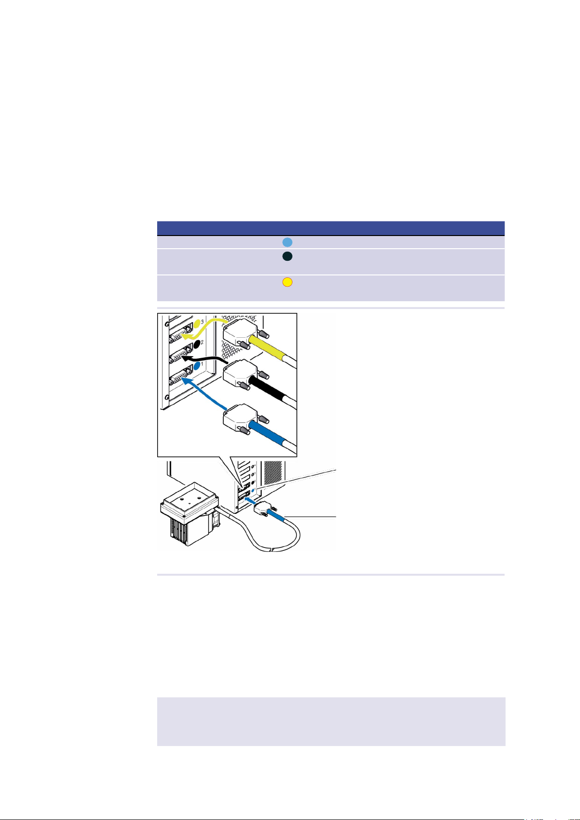
4.4.1. Fixation of Flat Bottom Plates
• Adjust the grub screws of the corner brackets for firm positioning of flat bottom
plates.
NOTICE
- Grub screws of the corner brackets may need adjusting for perfect t.
- Disposable xation via positioning brackets may not be necessary, if a thermal
adapter for temperature transfer is used → Removal of positioning brackets, chapter
4.5 below)
Fig.8: Contact plate with positioning brackets
NOTE
For ANSI/SLAS (formerly SBS) listed plates the maximum allowed torque is 0.3 Nm.
4.5. Removal of Positioning Brackets
(only for Thermoshake 7100146 and not for Thermoshake RM 7100144)
The positioning brackets of the Thermoshake 7100146 (grey brackets can be removed
in case it facilitates the positioning of the plates, given that a thermal adapter (insert,
nest) is installed on the Thermoshake.
• Unscrew the four vertical screws of the positioning brackets with a 1.5 mm socket
wrench (not within scope of delivery).
Fig.9: Removal of positioning brackets
Positioning brackets
with grub screws
screws of positioning brackets
INHECO 15
Doc ID: 900113-003
July 2020
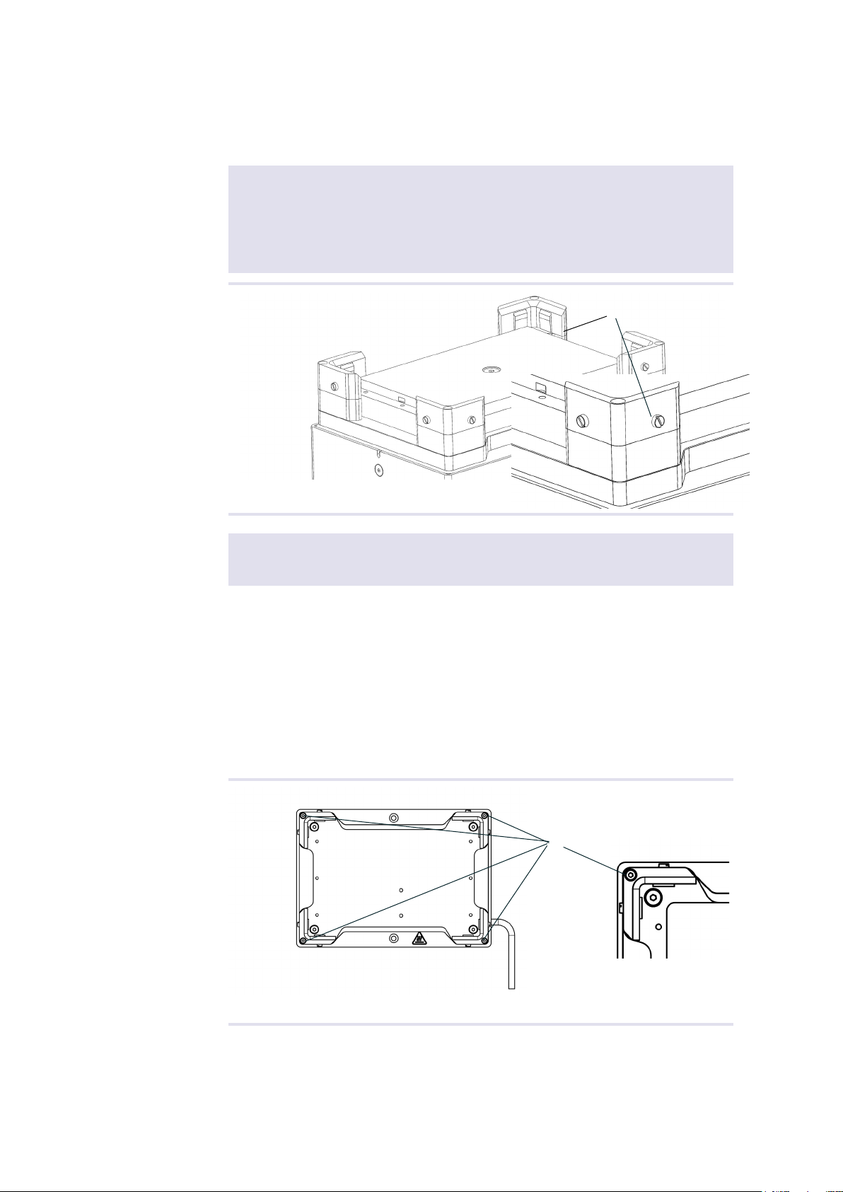
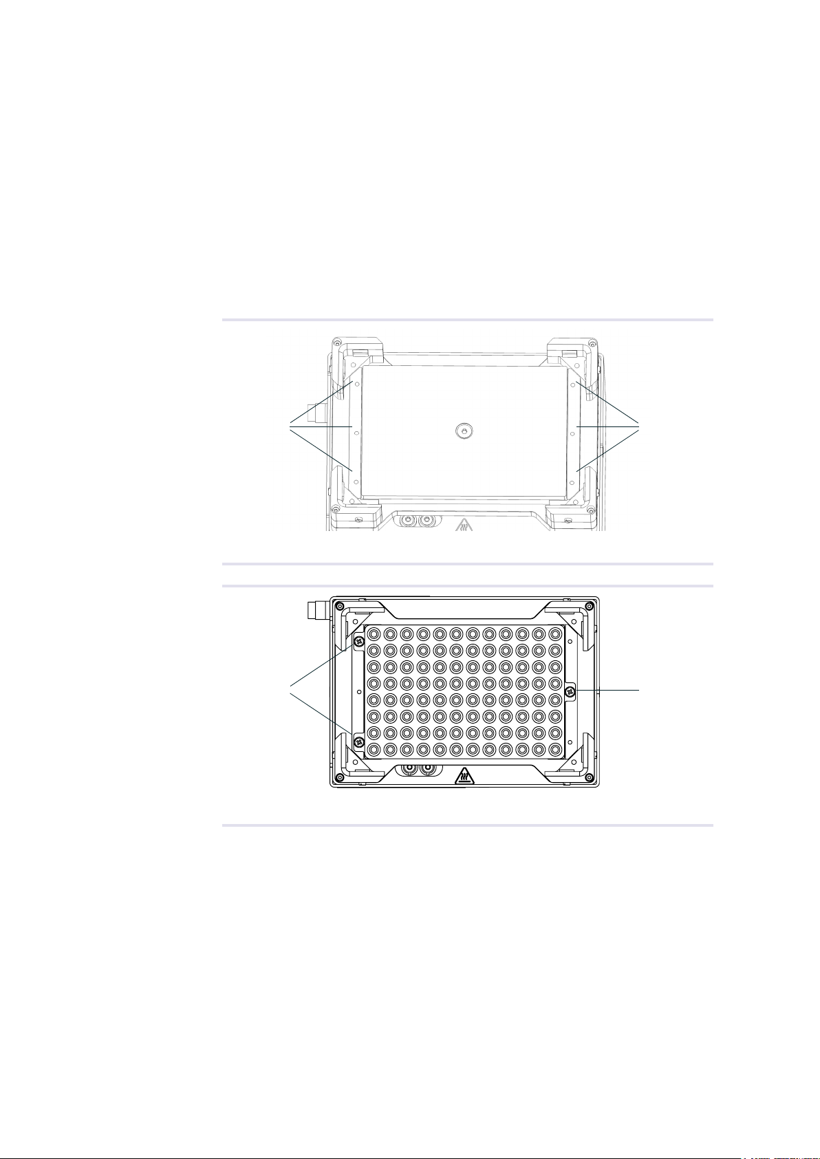
4.6. Installation of Adapter Plates (Inserts, Nests)
A thermal adapter is not needed for microplates with flat bottoms. Such plates can be
placed directly onto the temperature contact surface of the Thermoshake.
Custom-fit adapters are required for all tubes, reservoirs and plates without flat bottoms,
to ensure temperature transfer into the disposable/assay. The adapter may facilitate
accurate porsitioning for easy robotic handling plate.
Visit www.inheco.com to find the adapter which fits your tube, reservoir or plate. In case
custom design.
There are two orientations possible for the installation of the adapter plates.
Fig.10:
Thread M2.5x6 Thread M2.5x6
Threaded holes to x or unx the adapter plates
Fig.11:
HINWEIS: Sämtliche Informationen, die in diesem Dokument enthalten sind, sind STRENG VERTRAULICH. Jeder Empfänger
dieses Dokuments darf die darin enthaltenen Informationen, direkt oder indirekt, nur mit ausschliesslicher, schriftlicher Zustimmung
der INHECO GmbH an Dritte weitergeben oder offenlegen. Die INHECO GmbH behält sich alle Rechte in Bezug auf Urheberrechtsgesetz,
Patent- und Gebrauchsmusterschutz vor. Lizenzrechte werden hierdurch nicht erteilt.
7100146-A
BMU
002
Index
14.09.2012
MMomboisse
siehe
Zeichnung
Allgemeintoleranzen
Maßstab
Zeichnungsnummer
Benennung
Behandlung
Abmessungen
(mm)
Gewicht
(g)
Werkstoff
Oberfläche
siehe
Zeichnung
Werkstückkanten
Montag, 12. August 2013
INHECO GmbH
industrial heating and cooling
Variomag Thermoshake
\\IHC-SRV-0004\CALINK\CAL-DATA-PRODUCTION\IN_ARBEIT\71\7100146-A Thermoshake.SLDDRW
DIN ISO 2768 T1 - m
DIN ISO 2768 T2 - K
Zchng überarb. (AED92)
13.09.12
002
MMO
20.01.12
Zchng überarb. (AED81)
001
Ers.d.:
Ers.f.:
zuletzt gesp.:
Name
Datum
Änderung
Zust.
FEHLER!:Pruefer
FEHLER!:Pruefdatum
BMueller
24.03.2011
Name
Norm
Geprüft
Ersteller
Datum
SolidWorks; DIN A3
3511.00
Bl.
Blatt
1
1
1:1
NOTE: The information or material contained in this document is STRICTLY CONFIDENTIAL and any recipient
of this document shall not disclose or divulge, directly or indirectly, this document or the information or material
contained herein without the written consent of INHECO GmbH. All copyrights, trademarks, patents and other rights
in connection herewith are expressly reserved to INHECO GmbH and no license is created hereby.
GZ-01459_REL_04
Thread M2.5x6 Thread M2.5x6
Themoshake with installed PCR adapter plate
INHECO 16
Doc ID: 900113-003
July 2020
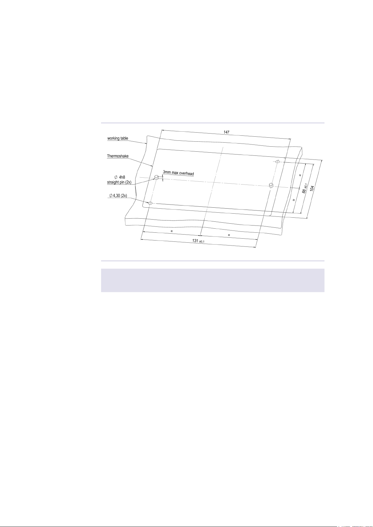
4.7. Mechanical Integration
The Thermoshake devices are usually integrated into liquid handling workstations. The
way of fixation depends on the hardware provided by the automation platform
manufacturer. When the Thermoshake devices are placed on a bench top, they must be
fixed to the ground with two M4 screws via the thread holes of the units. The ground
must be firm and even.
Drilling schematic for secure mounting of the Thermoshake unit on a working table is
shown in the following figure.
Fig.12: Drilling Scheme
NOTE
Thermoshake always needs to be xed to the ground for proper shaking performance.

INHECO 17
Doc ID: 900113-003
July 2020
5 SOFTWARE INSTALLATION
INHECO offers a software called Demo Tool to provide limited functional control (also
possible via touchscreen of the MTC/STC) and the opportunity to send manually
entered firmware commands to the devices.
We recommend to contact your workstation provider for integration (including software
integration) of the MTC/STC with devices into your workstation.
6 DAILY USAGE
The devices can be operated by touch-screen at the front panel of the MTC/STC, by the
Demo Tool software delivered by INHECO or by the software of your liquid handling
workstation. The INHECO Demo Tool software and the touch-screen allow
programming basic temperature and shaking sequences. More complex control
sequences can be performed with the software of your robotic platform provider or if you
write your own software based on our Firmware Command Set and DLL.
For more information consult the following documents:
- for touch-screen operation: MTC/STC Manual
- for software operation: Demo Tool Manual
- for firmware commands: MTC/STC Firmware Command Set
These documents can be downloaded from INHECO´ login section on
www.inheco.com.
6.1. Safety Instructions for Operation
Free air supply of the ventilation inlet and outlet must be ensured to avoid damage to the
unit.
NOTE
Do not operate the Thermoshake devices in an ambient temperature of more than 32°C
(90°F). Otherwise the devices may not work properly or may even get damaged.
Ensure that there is a minimum of at least 30 mm / 1.2 inches free of space between the
ventilation openings and adjacent devices or walls.
Fig.13: ventilation openings
WARNING
Devices can burn your skin. Even after switching off the TEC Control Unit, the
connected devices can still be hot and could seriously burn your skin as the material‘s
temperature can reach up to +70°C [+158°F]! It takes a while to cool down after the
device has been used.

INHECO 18
Doc ID: 900113-003
July 2020
7 MAINTENANCE
7.1. Software Updates
For updates of the Demo Tool Software, contact: [email protected] → How to contact
INHECO, page 6.
7.2. Trouble-Shooting & Support
In case of an operation failure follow the trouble-shooting instructions of this chapter.
INHECO needs the below mentioned information to help you troubleshooting the
operation failure.
Provide the following when contacting INHECO for support:
- INHECO product number of the device (shown on device label)
- INHECO product name of the device (shown on device label)
- INHECO serial number of the device (shown on device label or via software)
- Detailed error description
- Error code report (generated with software “MTC/STC Demo Tool”)
- Information about setup of devices:
○ integrated in workstation
○ controlled by MTC or STC (incl. part number and serial number)
○ controlled by workstation software or INHECO software
Serial numbers are shown on the device labels of the TEC Control Unit and connected
devices, but you can also read them out by using INHECO’s software “MTC/STC Demo
Tool” (Demo Tool). The Demo Tool must also be used to generate the above mentioned
report of error codes for the TEC Control Unit and all connected devices → Demo Tool
Manual.
Based on the above information, INHECO’s Techhotline decides about the requirement
of a return. → Return for Repair only with RMA Number, page 26.
7.2.1. Installation of the Software “MTC/STC Demo Tool”
The Demo Tool can be downloaded from INHECO´ login section on www.inheco.com.
In this section you will also find the Demo Tool Manual with detailed instructions of the
software.re.
Download the MTC/STC Demo Tool and the DLL file into the same folder. Both files
must be saved into the same folder, otherwise it is impossible to run the Demo
Tool.

INHECO 19
Doc ID: 900113-003
July 2020
7.2.2. Serial Numbers via Demo Tool
Start the Demo Tool and click on the button “find MTC” (or “find STC”). The software
scans all Com-Ports and subsequently displays the connected MTC/STC as well as
connected devices.
Fig.14: Command section of the User Interface
• Make sure the Refresh Box is unchecked (as in Fig. 14).
• Enter your command into the command field. (overwrite the last command shown in
this field e.g. last command was 0RFV1).
• Select button “Send Command”.
• Enter following Commands:
○ for MTC/STC Mainboard serial number: 0RFV2
○ for Slot Module serial number: xRFV2 (x=slotID: 1-6)
○ for external connected device: RSNx (x=slotID: 1-6)
7.2.3. Error Code Report generated with “MTC/STC Demo Tool”
• Start the Demo Tool.
• Click on the button “find MTC” (or “find STC”).
The software scans all Com-Ports and subsequently displays the connected MTC/
STC as well as connected devices.
• Click on the button “report error codes”.
An additional window appears in which all error codes are displayed. Email a
screenshot of this window along with all other required information to

INHECO 20
Doc ID: 900113-003
July 2020
7.3. Maintenance (Relling of Cooling Liquid Reservoir and Pump)
The Thermoshake needs a well defined minimum level of cooling liquid to work properly
and to avoid damages to the system. To ensure that the Thermoshake does not run dry
INHECO implemented a sensor to check the liquid level of the cooling liquid. The sensor
can be addressed with a command to report the cooling liquid level. This command can
be integrated into your daily routine with different ways:
- integrated in workstation software (→ contact your workstation provider to receive
information)
- integrated in start up routine of MTC/STC (error displayed on touch-screen → chapter
7.3.3)
- integrated in the error code report of INHECOs Demo Tool software (→ chapter 7.3.4)
- manually send via INHECOs Demo Tool software (→ RRS Command, chapter 7.3.4)
7.3.1.
NOTE
In any case we recommend to rell the Thermoshake at least every 3 months.
Rell Tools delivered with Thermoshake
- 100ml cooling liquid (23% ethanol, 77% distilled water)
- syringe to fill the reservoir
- socket wrench (2mm) to open filling nozzle
7.3.2. Rell Procedure
• Switch off the power of the MTC/STC.
• Unplug the Thermoshake from the MTC/STC.
• Loose the screw plugs of the cooling fluid reservoir (→ fig. 15).
• Fill the reservoir with the injection syringe delivered with the Thermoshake until the
liquid is visible in the filling nozzle.
•
NOTE
Use the original INHECO cooling uid or a mixture of 23% ethanol and 77% distilled
water to avoid damage to the unit.
Insert the needle of the empty syringe as deeply as possible into the filling nozzle and
extract as much of the fluid as possible.
•
NOTE
This method ensures that the reservoir contains cooling uid at the maximum lling
level.
Close the reservoir with the screw plugs of the cooling fluid reservoir.
NOTE
Never leave the reservoir open.
• Connect the Thermoshake with the MTC/STC.
• The Thermoshake is now ready again for use.
Fig.15: Screw plugs of the cooling uid reservoir
Screw plugs
This manual suits for next models
11
Table of contents
Other INHECO Accessories manuals

Popular Accessories manuals by other brands

Geermarc
Geermarc CLEARSOUND AMPLICALL 16 manual

NOVACARE
NOVACARE Wellness Oasis user manual

IVT
IVT AZ-F900DN Operation manual

Scott Fetzer
Scott Fetzer Carefree of Colorado Eclipse Universal installation manual

Hall Research Technologies
Hall Research Technologies EMX-HD-AUD user manual

Universal Remote Control
Universal Remote Control MRZ-260 - SPECS SHEET Specification sheet


