initium Promi-ESD-02 User manual

Promi-ESD-02 User Manual ver 1.1
www.initium.co.kr
1
by Bluetooth
Enabling Wireless Serial Communications
Promi-ESD-02
User Manual
Version 1.1

Promi-ESD-02 User Manual ver 1.1
www.initium.co.kr
2
Revision History: User Manual of Promi-ESD-02™
Version Changed Contents Date
1.1 Draft version 06/04/2004

Promi-ESD-02 User Manual ver 1.1
www.initium.co.kr
3
Contents
1. Product Description .........................................5
1.1 About Promi-ESD™ .................................................................................................... 5
2. Technical Specifications ..................................6
2.1 Pin Assignment.............................................................................................................. 6
2.2 Electrical Characteristics ............................................................................................... 7
2.3 Hardware Design........................................................................................................... 8
2.4 How to make a RS232 interfaced Jig Board ................................................................. 9
2.5 Power Consumption .................................................................................................... 10
2.6 Temperature ................................................................................................................ 10
2.7 Serial Interface ............................................................................................................ 11
2.8 Bluetooth Interface ...................................................................................................... 11
3. Configuration ..................................................12
3.1 Using Promi-WIN™ ................................................................................................... 12
3.1.1 Making the first Promi-SDTM/Bluetooth connection 12
3.1.2 Setting Operating Mode for Automatic Connection 18
3.2. Using a Terminal Program.......................................................................................... 19
3.2.1 Connecting Promi-SD™ to host. 19
3.2.2 Making the first Promi-SD™/Bluetooth connection 20
3.2.3 Making Promi-SD™ do INQUIRY SCAN and PAGE SCAN 21
3.2.4 Releasing the existing Bluetooth connection 22
3.2.5 Automatic connection of two Promi-SD™ Units 23
3.2.6 AT command vs. Operational Status 24
4. For Multi-Serial Connections ......................26
4.1 Promi-MSP™ ............................................................................................................ 26
5. Legal Notice ....................................................27
6. About this Manual...........................................29

Promi-ESD-02 User Manual ver 1.1
www.initium.co.kr
4
Appendix A: AT command sets............................30

Promi-ESD-02 User Manual ver 1.1
www.initium.co.kr
5
1. Product Description
1.1 About Promi-ESD™
Promi-ESD-02 is a board type of Promi-SD™, Class 2 OEM version, which can be
embedded in your applications such as mobile terminals or any kinds of machines
for Wireless serial communications of long range, easy-to-install, and low-cost.
Provided is point-to-point wireless connection without standard RS232 cables.
For point-to-multipoint connections, please refer to our Promi-MSP™, providing all
the features of RS485.
Model Name Part No. Spec.
Promi-ESD-02 ESD00-10200 Class 2 / Output Power: 2.5mW (4dBm)
3.3V DC power supply
Integrated antenna on the board
w/ Setup Software & manual on CD
Specification
zOutput Interface UART
zCompliant Bluetooth Specification v1.1
zTransmission Power Class 2(max 4dBm)
Dimensions: 18 x 20 (mm)

Promi-ESD-02 User Manual ver 1.1
www.initium.co.kr
6
2. Technical Specifications
2.1 Pin Assignment
Physical Dimension
Pin number Pin name Direction Description Signal Level
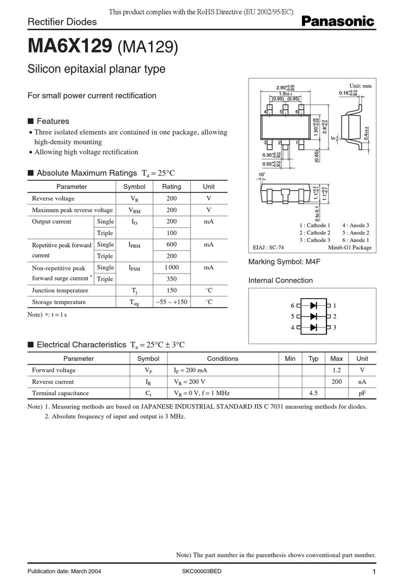
1 GND I Power Ground Ground
2 VDD I DC input (3.0 ~ 3.3V input) Power
3 STATUS O Status TTL
4 /RST I Reset (Active low) TTL
5 CTS I
UART Clear to Send TTL
6 RTS O
UART Ready to Send TTL
7 TXD O UART data out TTL
8 RXD I UART data input TTL

Promi-ESD-02 User Manual ver 1.1
www.initium.co.kr
7
2.2 Electrical Characteristics
Absolute Maximum Ratings
Operating Condition (Min Max
Operating Temperature Range -40°C85°C
VDD -0.4V 3.7V
Recommended Operating Conditions
Operating Condition (Min Max
Operating Temperature Range -20°C70°C
VDD 3.0V 3.6V
※For safe operation, supply power of 3.3V.
Input/Output Terminal Characteristics
Digital Terminals Min Typ Max Unit
Input Voltage
VIL input logic level low (VDD=3.0V) -0.4 - 0.8 V
VIH input logic level high 0.7VDD - VDD+0.4 V
Output Voltage Input
VOL output logic level low, (lO = 4.0mA), - - 0.2 V
VOH output logic level high, (lO = -4.0mA), VDD-0.2 - - V

Promi-ESD-02 User Manual ver 1.1
www.initium.co.kr
8
2.3 Hardware Design
1) If you would like to supply 5~12V power to Promi-ESD, you need to regulate the power
to be 3.3V as in below. ( Min. 100mA regulator )
C?
10uF
U?
L1117L-3.3
3 2
4
1
Vin Vout1
Vout2
GND
C?
10uF
DC3P3VVCC
Input to each signals when 5V power supplied.
R1
68K
/RST
CSR_TXD
CSR_RXD
TXD
CSR_RST
R4
115K
RTS
CSR_RTS
R3
68K
R7
68K
R8
115K
RXD
CSR_CTS
R2
115K
CTS

Promi-ESD-02 User Manual ver 1.1
www.initium.co.kr
9
2) If you are not using Hardware flow control (handshaking), please bridge ESD_CTS
and ESD_GND to disable the function.
2.4 How to make a RS232 interfaced Jig Board
DC3P3V
TXD
C?
10uF
/RST
RS_DCD
RS_DTR
DTR
RXD
U?
MAX3238/SO
2
26
16
15
28
25
1
3
27
4
13
14
24
23
22
19
17
8
9
11
21
20
18
5
6
7
10
12
GND
VCC
R1OUTB
INVALID
C1+
C1-
C2+
C2-
V+
V-
FORCEON
FORCEOFF
T1I N
T2I N
T3I N
T4I N
T5I N
R1IN
R2IN
R3IN
R1OUT
R2OUT
R3OUT
T1OUT
T2OUT
T3OUT
T4OUT
T5OUT
U?
L1117L-3.3
3 2
4
1
Vin Vout1
Vout2
GND
C?
0.1UF
RS_DSR
IN_PWR
C?
10uF
JH?
CONN PWR 3-H
3
2
1
3
2
1
STATUS
DC3P3V
RS_CTS
RS_DTR
C?
0.1UF
DC3P3V
P?
CONNECTOR DB9
5
9
4
8
3
7
2
6
1
STATUS
D?
LED_2
21
C? 0.1UF
JP?
2.54mm
8
7
6
5
CSR_CTS
/RST
DC3P3V
MALE
DCD
CSR_TXD
DC3P3V
C? 0.1UF
RS_TXD
RS_DSR DSR
CSR_RTS
RS_RTS
RS_RXD
RS_RXD
S?
SW
1 3
C?
0.1UF
RTS
RS_RTS
RS_TXD
DC3P3V
CSR_RXD
JP?
2.54mm
1
2
3
4
IN_PWR
R?
20k
D?
?
1 2
CTS
RS_DCD
R?
330
RS_CTS

Promi-ESD-02 User Manual ver 1.1
www.initium.co.kr
10
2.5 Power Consumption
Condition Current Consumption
If NOT connected to Host 1 mA
If connected to Host 1 mA
For data communications with Host only 8 mA
During INQUIRY mode 48 mA
For Master connection 48 mA
During SCAN (page & inquiry) mode 19 mA
Park mode 8 mA
Non-Park mode 10 mA
Data Com. (9600bps) 28 mA
Data Com. (115000bps) 38 mA
* Low Power Mode
If you want to use low power mode to save power, use AT command “AT+BTLPM".
If you set "AT+BTLPM,1", low power mode will be functioned.
2.6 Temperature
Model No.: Promi-ESD-02
Recommended operating conditions: -20’C~75’C
Storage conditions: -40’C~85’C

Promi-ESD-02 User Manual ver 1.1
www.initium.co.kr
11
2.7 Serial Interface
Model No.: Promi-ESD-02
RS232, 1200~230000 baud,
CTS/RTS flow control or no flow control
2.8 Bluetooth Interface
Bluetooth Specification V 1.1
Level 4 dBm
Range ~30m
Bluetooth protocols RFCOMM, L2CAP, SDP
Supported Profiles General Access Profile
Serial Port Profile

Promi-ESD-02 User Manual ver 1.1
www.initium.co.kr
12
3. Configuration
3.1 Using Promi-WIN™
To configure Promi-ESD, you need to prepare RS232 interfaced jig board.
1. Please connect Promi-ESD to RS232 interfaced jig board you prepared.
2. Connect the Jig board to your Host PC.
3. Supply power to the Jig board.
4. Start PromiWIN software on your Host PC and you may configure the Promi-ESD.
Configuration flow of Promi-ESD is same as the flow of Promi-SD.
Users may consider Promi-SD as Promi-ESD in the manual below.
3.1.1 Making the first Promi-SDTM/Bluetooth connection
To make Bluetooth wireless connections with SD, first connect the SD to a host
computer running PromiWINTM as instructed below. Then activate SD INQUIRY
SCAN and PAGE SCAN from PromiWINTM.
Let’s suppose there are 2 Promi-ESD™s, SD1 and SD2:
1. Connect the SD1 to a host serial port and turn on the SD.
2. Check the SD1 STATUS LED color. Amber indicates standard mode. Start the
PromiWINTM configuration program by clicking the program icon under
Start/Programs/PromiWINTM.
3. Please open PromiWIN ÆPromWIN configuration menu to set up the
PromiWIN to be matched with Promi-ESD.

Promi-ESD-02 User Manual ver 1.1
www.initium.co.kr
13
Check COM port number of your PC where Promi-SD is plugged in.
Check BaudRate/Parity/StopBit. Users need to select the correct
configuration value of Promi-ESD to start.
Default Setting of Promi-ESD: 9600/NoParity/ One Stop bit. Users may NOT
change the configuration of Promi-ESD, the job should be done at
DeviceSetting menu
4. Select Promi-SD ÆStart Configuration in the menu. Information will be
displayed as shown in Figure 1.

Promi-ESD-02 User Manual ver 1.1
www.initium.co.kr
14
Figure 1
Device Name: Shows default device name of Promi-SD. Ex) PSDv3a-120296
PSDv3a
means the version of firmware of Promi-SD.
Users may change the Device name at Device Setting page.
Device Hardware Address: Default Bluetooth Device Address.
Current Mode: This show current operation MODE of Promi-SD.
Current Status: Status of Promi-SD operation: Standby / Pending/ Connect.
Security: This shows current Security setting values.
Uart Setting: Shows current setting of UART. If users want to change Baud
Rate/ StopBit/ Parity, please go to Device Setting page.
5. Click the ‘Device Setting’ icon in the list control box.
Figure 2.
Operation Mode:
Mode0: Default Mode to set up Bluetooth connection
Mode1: Mode1 & Mode 2 are for secure connection. Promi-SD that has
been set to Mode1 will try connection to the last connected
device only.
Mode2: Promi-SD that has been set to Mode2 will wait fro connection from

Promi-ESD-02 User Manual ver 1.1
www.initium.co.kr
15
the last connected device only.
Mode3: In Mode3, Promi-SD will be discoverable/connectable by any kind
of Bluetooth devices. If users want to make a connection between
Promi-SD and other Bluetooth CF cards or USB dongles, please
set Mode3. For more information, please refer to the Trouble
shooting guide of this manual.
*Promi-SDs which are paired using Mode1 & Mode2 will be
automatically connected, unless Mode setting is changed.
Uart: To change the Baud rate/Parity/StopBit, please use this Uart setting menu.
*NOTE: Please do not confuse with PromiWIN configuration menu.
PromiWIN configuration menu will only set the configuration of
PromiWIN. To Change the configuration of Promi-SD, users must
use this Uart setting menu in Red circle above.
Security Option: Users may set the security option. Authentication/ Encryption/
password.
Device Name: Users may change the device name to be more friendly.
Signal: If users want to remove the response signals from Promi-SD, such as
OK, CONNECT, DISCONNECT, ERROR on each events, users may

Promi-ESD-02 User Manual ver 1.1
www.initium.co.kr
16
turn off the signal here. This can be done by ATS10=n command.
6. Click the ‘Connection(in)’ icon in list control box. Check both options and then
click the ‘Start’ button as shown in Figure 3. The SD1 now starts INQUIRY
SCAN and PAGE SCAN operations. During the operation, the STATUS LED
will flash green, twice every 3 seconds.
Figure 3.
7. After the INQUIRY SCAN and PAGE SCAN setting of the SD1 is finished ,
please plug out SD1. Then plug in another SD to connect to SD1, SD2,
may be connected to the host.
8. Select PromiWINTM and repeat the preceding procedure for SD2
9. Select the ‘Connection(out)’ icon in the list control box and click the search
button.
10. Now the additional SD2 enters INQUIRY operation.

Promi-ESD-02 User Manual ver 1.1
www.initium.co.kr
17
Figure 4.
11. From the ‘Search Result’ menu click the item with ‘Promi-SD1’ as its
DEVICE_NAME.
12. Once selected, its BD_ADDR will appear in the dialog box on the right side of
the ‘Connect to…’ button.
13. Click the ‘Connect to…’ button and the ‘Successful Connection’ Popup box will
appear as shown in Figure 5.
Figure 5.
14. To release the first Bluetooth wireless connection between the SD units click
the ‘Disconnect’ button.
15. For automatic connection setup, set SD1 as Mode 2 and SD2 as Mode 1.
To utilize the SD automatic connection feature, make a Bluetooth connection
between two SD units. Once connected, one SD stores the 48-bit BD_ADDR
of its counterpart.

Promi-ESD-02 User Manual ver 1.1
www.initium.co.kr
18
To expedite the 48-bit BD_ADDR input operation, SD is designed to store the
BD_ADDR of its latest counterpart.
3.1.2 Setting Operating Mode for Automatic Connection
New SD units are default set to ‘MODE 0’. For SD automatic connection
change the operating mode of an SD to MODE 1 and another to MODE 2.
The following simple steps describe the SD operating mode change
procedure.
1. After making a Bluetooth wireless connection between two SD units, set the
operating mode of one SD to MODE 1, as shown in Figure 6.
Figure 6.
2. Set the operating mode of another SD to MODE 2 as shown below.

Promi-ESD-02 User Manual ver 1.1
www.initium.co.kr
19
Figure 7.
3. Turn off both SD power supplies. From now, when both SD units are
powered up again, they will automatically connect. (To release this feature,
reset both SD units. Amber SD STATUS LED indicates successful reset
process.)
3.2. Using a Terminal Program
Promi-SDTM units are easily controlled and configured via PromiWINTM . Likewise
functions are accomplished via any terminal program such as HyperTerminal. AT
command sets supported by Promi-SDTM add sophistication to Promi-SDTM control.
3.2.1 Connecting Promi-SD™ to host.
For SD use, follow the simple instructions below:
1. Connect an SD to a host serial port. Then, turn on the SD.
2. Check the STATUS LED color. Amber indicates standard mode.

Promi-ESD-02 User Manual ver 1.1
www.initium.co.kr
20
3. Execute any terminal program and activate Local Echo.
4. Configure the host serial port to match the SD unit configuration. The SD
default configuration is 9600 bps Baud, 8 Data bit, No Parity, 1 Stop bit and
H/W flow control.
5. Enter ‘AT’ command at the prompt. An SD ‘OK’ reply indicates proper
operation.
3.2.2 Making the first Promi-SD™/Bluetooth connection
As stated before, Bluetooth wireless connections can be made with any other
Bluetooth device supporting Bluetooth SPP (Serial Port Profile). For Bluetooth
wireless connections to an SD, first make another SD ‘Discoverable’ and
‘Connectable’. In this case, refer to section 3.3 before following the
instructions below.
1. First check the status of the SD by entering ‘AT+BTINFO?’. The SD
response is comprised of BD_ADDR, Device Name, Operating Mode,
Operating Status, Authentication and Encryption flags. To make connection
to other Bluetooth devices, the operating status of the first SD should be
‘STANDBY’. A ‘PENDING’ operating status of the first SD indicates the
unit is busy with another operation. In this case, cancel the ongoing
operation by entering the ‘AT+BTCANCEL’ command.
2. Search other local Bluetooth devices by entering the ‘AT+BTINQ?’ command.
AT+BTINFO?
000B530000A9,PSDv2g-0000A9,MODE0,STANDBY,0,0
OK
Table of contents
