Page 3 of 13
6. Using the down arrow, scroll until you see SAVE NVRAM.
7. Press ENTER and ENTER again to confirm.
8. Set printer online.
9. Power OFF your printer.
Transferring the Ink Chips
Remove original cartridges from your printer.
Open the cartridges of the Bulk System.
Transfer the Ink Chips from your original cartridges to the cartridges of this bulk system.
If the bulk system’s cartridges do not have any color tabs removed, you should do so
when you have transferred chips. Each chip must be valid, with at least 20% of ink level
left on it. Lower level may cause RIP software to show warning messages of low ink.
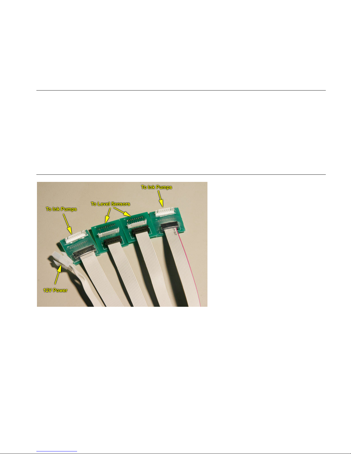
Installing the Electronic Control Devices
Each of the two electronic devices
supplied with Pro-CP2 bulk system
has a wide ribbon cable terminated
with 4 boards and one 2-pin
connector for the 12-volt power.
Two of the boards are shrink-
wrapped – they go to the pumps
compartment. The other two
boards will be connected to the ink
level sensors of the secondary
tanks (ink bags).
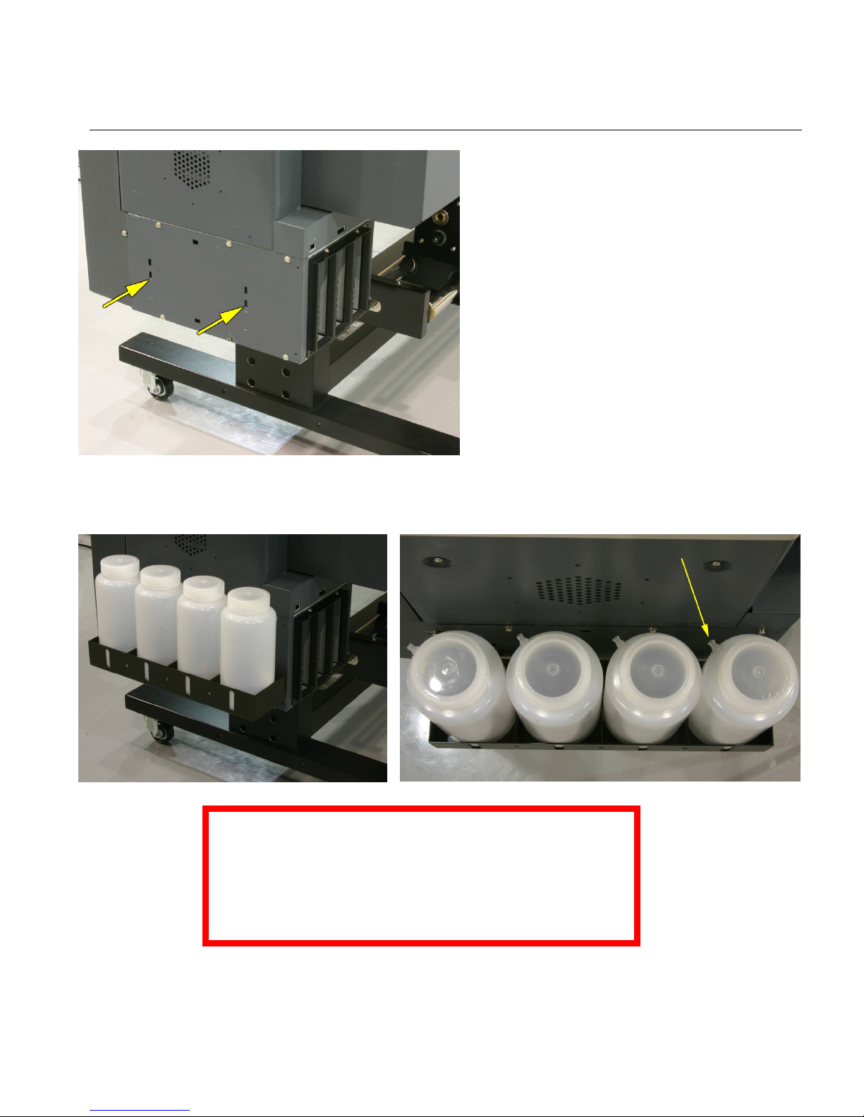
Remove the covers from the
printer:
- covers over the secondary
tanks on both sides;
- covers over ink pumps on
both sides;
- covers with holes for air exhaust.
Route the ribbon cable ends designated for ink level sensor connection, into the ink level
sensor area. The other ends must go into the area of the ink pumps.
The square boards for ink level sensor connections have 9-pin and 10-pin receptacles (at
the bottom, not visible on the picture above).
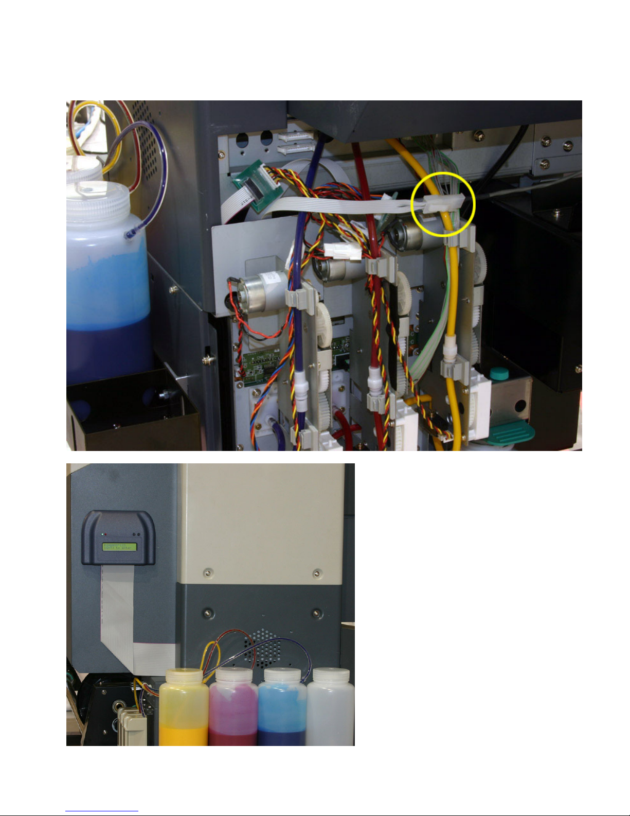
Connect these receptacles to the panel-mounted white headers. Connect the Seiko
receptacles to the white connectors on top of the boards. You cannot mistake because the
left connector is 10-pin and the right one is 9-pin.
You may need to cut the nylon tie around the ink tubing if it interferes with the
installation of the right board.