InnoMedia MTA8000 Series User manual

V10, June 2022
InnoMedia MTA8000 Series
Administrative Guide
INNOMEDIA CONFIDENTIAL
This document contains proprietary information of InnoMedia Inc., and its receipt or possession does not
convey any rights to reproduce, disclose its contents, or to manufacture, use or sell anything it may describe.
It may not be reproduced, disclosed or used without specific written authorization of InnoMedia Inc.

InnoMedia MTA8000 Series Administrative Guide
Page 2
Copyright © 2022 InnoMedia. All rights reserved.
Table of Contents
1Introduction .................................................................................................................................................8
1.1 Product Overview...................................................................................................................................8
1.2 Package Contents ...................................................................................................................................8
1.2.1 Residential models: MTA8328-1N, MTA8328-1W, MTA8328-1NP, MTA8328-1WP, MTA8338-1N
......................................................................................................................................................8
1.2.2 Business Models MTA8328-MP: MTA8328-4, MTA8328-8, MTA8328-24....................................9
1.3 Residential Models: Out of the Box Setup .............................................................................................9
1.3.1 MTA8328-1W WiFi Connection Optimizer (WCO) Test ..............................................................10
1.4 Business Models: Out of the Box Setup ...............................................................................................12
1.5 Terminology and Usage........................................................................................................................12
2Home -- Device States................................................................................................................................13
3Network .....................................................................................................................................................16
3.1 IP Address Configuration for MTA........................................................................................................16
3.1.1 Network Operation Mode ..........................................................................................................16
3.1.2 DHCP Server Setting....................................................................................................................16
3.1.3 Ethernet IP Address Setting ........................................................................................................17
3.1.4 WiFi Configuration and IP Address Setting .................................................................................18
3.1.5 LAN Interface IP Address Setting ................................................................................................18
3.1.6 Host and DNS Servers .................................................................................................................18
3.1.7 Master DNS.................................................................................................................................19
3.1.8 TOS Setting..................................................................................................................................20
4Telephony ..................................................................................................................................................22
4.1 Profile Config........................................................................................................................................22
4.1.1 SIP Server Setting........................................................................................................................22
4.1.2 Security Setting...........................................................................................................................25
4.1.3 Codec Setting..............................................................................................................................26
4.1.4 SIP Timer Setting.........................................................................................................................27
4.1.5 DigitMap Setting .........................................................................................................................29
4.1.6 Feature and Service Code Setting...............................................................................................33
4.1.7 Fax Setting ..................................................................................................................................35
4.1.8 Call Report Setting ......................................................................................................................36
4.2 Port Config............................................................................................................................................36
4.2.1 SIP Account Setting.....................................................................................................................37
4.2.2 Features Setting..........................................................................................................................37
4.2.3 Line Setting .................................................................................................................................38
4.2.4 Speed Dial ...................................................................................................................................39
4.2.5 IMS related SIP settings ..............................................................................................................40
4.3 Telephony Region and Misc Setting .....................................................................................................40
4.3.1 Media Port Setting......................................................................................................................40
4.3.2 Regional Setting ..........................................................................................................................41
4.3.3 Tone Cadence Setting .................................................................................................................41
4.3.4 Ring Cadence Setting ..................................................................................................................43
4.4 Line Diagnostics....................................................................................................................................44

InnoMedia MTA8000 Series Administrative Guide
Page 3
Copyright © 2022 InnoMedia. All rights reserved.
4.4.1 GR909 Tests: triggered from the WEB Administrative Console..................................................44
4.4.2 GR909 Tests: triggered from SIP NOTIFY Message .....................................................................45
5System........................................................................................................................................................46
5.1 Account Settings...................................................................................................................................46
5.1.1 Administrator Account Setting ...................................................................................................46
5.1.2 End User Account Setting ...........................................................................................................46
5.2 Page Permission ...................................................................................................................................46
5.3 Firmware Upload..................................................................................................................................47
5.4 Reboot..................................................................................................................................................48
5.5 Restore To Factory ...............................................................................................................................48
5.6 Provisioning Setting..............................................................................................................................49
5.6.1 Provisioning Parameters.............................................................................................................49
5.6.2 Provisioning Factory Default Settings to Devices Deployed in the Field ....................................51
5.7 EMS Setting ..........................................................................................................................................52
5.7.1 EMS Server..................................................................................................................................52
5.8 Trace Log ..............................................................................................................................................53
5.8.1 Trace Log Setting.........................................................................................................................53
5.9 System Time .........................................................................................................................................55
5.9.1 Time Setting................................................................................................................................55
5.10 Language ..............................................................................................................................................57
5.11 Uplink Connection................................................................................................................................57
5.12 Certificate & Key...................................................................................................................................58
5.13 Config File.............................................................................................................................................58
5.14 SNMP Setting........................................................................................................................................59
5.15 Remote Access .....................................................................................................................................60
5.15.1 Remote Access Setting................................................................................................................60
6CLI Command references...........................................................................................................................60
Appendix A LED States......................................................................................................................................62
Model MTA8328-1W......................................................................................................................................62
Model MTA8328-1N / MTA8338-1N ..............................................................................................................63
Model MTA8328-4, MTA8328-8, MTA8328-24..............................................................................................64
Appendix B The use of encryption key methods .............................................................................................65
Inno rc4_102 ..................................................................................................................................................65
Openssl command example ...........................................................................................................................65
Appendix C: WiFi Connection Setup through Captive Portal..............................................................................66
Appendix D –Provisioning through DHCP Options.............................................................................................68
Method 2 –Use both DHCP Option 66 and DHCP Option 67 together .....................................................68
Important Note:.........................................................................................................................................68

InnoMedia MTA8000 Series Administrative Guide
Page 4
Copyright © 2022 InnoMedia. All rights reserved.
Table of Figures
Figure 1. Residential MTA Package.......................................................................................................................8
Figure 2. MTA8328-1N Front and back panel (Example)......................................................................................8
Figure 3. MTA8328-MP business models (4, 8, and 24 FXS port models) ............................................................9
Figure 4. Setup the Residential MTA device to connect to the router or network switch ...................................9
Figure 5. WCO test result....................................................................................................................................11
Figure 6. Setup the MTA in a business environment..........................................................................................12
Figure 7. Login Screen - Input Username and Password. MTA8328-1N login screen example. ........................13
Figure 8. Current status of MTA8328-1N (as an example) .................................................................................14
Figure 9. Configure the Operation Mode ...........................................................................................................16
Figure 10. Configure the DHCP Server................................................................................................................16
Figure 11. Configuring the IP Address on the Ethernet Interface.......................................................................17
Figure 12. WiFi Configuration and IP Address Setting ........................................................................................18
Figure 13. Configure the LAN IP address ............................................................................................................18
Figure 14. Configuring the host information on the device ...............................................................................19
Figure 15. Configuring the Master DNS Information..........................................................................................20
Figure 16. TOS Setting ........................................................................................................................................20
Figure 17 Configuring Telephony options...........................................................................................................22
Figure 18. SIP Server Setting—SIP Proxy Server .................................................................................................22
Figure 19. SIP Server Settings –SIP Option.........................................................................................................24
Figure 20. MTA Security Settings........................................................................................................................25
Figure 21. Codec Setting.....................................................................................................................................26
Figure 22. SIP Timer Setting................................................................................................................................27
Figure 23. Digitmap Setting ................................................................................................................................29
Figure 24. FXS Setting .........................................................................................................................................32
Figure 25. Feature and Service Code Setting......................................................................................................33
Figure 26. Fax Setting .........................................................................................................................................35
Figure 27. CDR Setting ........................................................................................................................................36
Figure 28. Phone port status overview...............................................................................................................36
Figure 29. SIP Account Setting............................................................................................................................37
Figure 30. Call Feature Setting............................................................................................................................37
Figure 31. Line Setting ........................................................................................................................................38
Figure 32. Speed Dial ..........................................................................................................................................39

InnoMedia MTA8000 Series Administrative Guide
Page 5
Copyright © 2022 InnoMedia. All rights reserved.
Figure 33. IMS Settings .......................................................................................................................................40
Figure 34. Media Port Setting.............................................................................................................................40
Figure 35. Regional settings for power and analog line specifications...............................................................41
Figure 36. Tone Cadence Setting ........................................................................................................................42
Figure 37. Ring Cadence Setting .........................................................................................................................43
Figure 38. GR909 Line Test (illustrative example showing a four port ATA) ......................................................44
Figure 39. Administrator account setting...........................................................................................................46
Figure 40. User Account Setting .........................................................................................................................46
Figure 41.User Page Permission Setting ............................................................................................................47
Figure 42. Firmware Upload ...............................................................................................................................47
Figure 43. Reboot Dialog ....................................................................................................................................48
Figure 44. Restore To Factory Dialog..................................................................................................................48
Figure 45. Provisioning Server Setting................................................................................................................49
Figure 46. Configuring EMS Server Information .................................................................................................52
Figure 47. Trace Log Setting ...............................................................................................................................54
Figure 48. Time Setting.......................................................................................................................................56
Figure 49. Language Selection for IVR system....................................................................................................57
Figure 50. Uplink Detection Settings ..................................................................................................................57
Figure 51. Certification & Key.............................................................................................................................58
Figure 52. System Config ....................................................................................................................................58
Figure 53. SNMP Setting .....................................................................................................................................59
Figure 54. Protocol and Port Settings for Remote Access ..................................................................................60
Figure 55. Captive Portal - Welcome ..................................................................................................................66
Figure 56. Captive Portal –SSID selection ..........................................................................................................66
Figure 57. Captive Portal –SSID password input................................................................................................67
Figure 58. Captive Portal –Confirm settings ......................................................................................................67

InnoMedia MTA8000 Series Administrative Guide
Page 6
Copyright © 2022 InnoMedia. All rights reserved.
About This Document
This document provides details of the features available on the InnoMedia MTA8000 series as well as feature
descriptions and the configurations required.
Revision History
Date
Version
Notes
2016/10/25
V1.0
Based on firmware V1.0.0.19
2016/11/08
V1.1
Based on firmware V1.0.0.23
2016/11/23
V1.1
Based on firmware V1.0.0.27
2017/03/25
V5
Based on firmware V1.0.5.1
2017/04/07
V6
Based on firmware V1.0.5.3
2018/06/25
V7
Add high density port models
2019/04/08
V8
Add Router/Switch mode features
2022/02/03
V9
Add MTA8338-1N model
2022/05/31
V10
Based on firmware V1.0.22.66/1.0.0.7

InnoMedia MTA8000 Series Administrative Guide
Page 7
Copyright © 2022 InnoMedia. All rights reserved.
Federal Communication Commission Interference Statement
The MTA8000 series of products have been tested and found to comply with the limits for a Class B digital
device, pursuant to Part 15 of the FCC Rules. These limits are designed to provide reasonable protection
against harmful interference in a residential installation. This equipment generates, uses and can radiate
radio frequency energy and, if not installed and used in accordance with the instructions, may cause harmful
interference to radio communications. However, there is no guarantee that interference will not occur in a
particular installation. If this equipment does cause harmful interference to radio or television reception,
which can be determined by turning the equipment off and on, the user is encouraged to try to correct the
interference using one of the following measures:
● Reorient or relocate the receiving antenna.
● Increase the separation between the equipment and receiver.
● Connect the equipment into an outlet on a circuit different from that to which the receiver is connected.
● Consult the dealer or an experienced radio/TV technician for help.
FCC Caution: Any changes or modifications not expressly approved by the party responsible for compliance
could void the user’s authority to operate this equipment.
This device complies with Part 15 of the FCC Rules. Operation is subject to
the following two conditions: (1) This device may not cause harmful
interference, and (2) this device must accept any interference received,
including interference that may cause undesired operation.
IMPORTANT NOTE:
FCC Radiation Exposure Statement:
This equipment complies with FCC radiation exposure limits set forth for an uncontrolled environment. This
equipment should be installed and operated with a minimum distance of 20cm between the radiator & your
body.
InnoMedia MTA8000 Series Administrative Guide
Page 8
Copyright © 2022 InnoMedia. All rights reserved.
1INTRODUCTION
1.1 Product Overview
The InnoMedia MTA8000 series is an integrated device providing telephony service over a broadband
network.
It allows the connection of your device to a Router/Firewall through either a wired Ethernet connection or
through WiFi
1
. This guide will help you to quickly install and configure your unit so that you can start placing
calls right away.
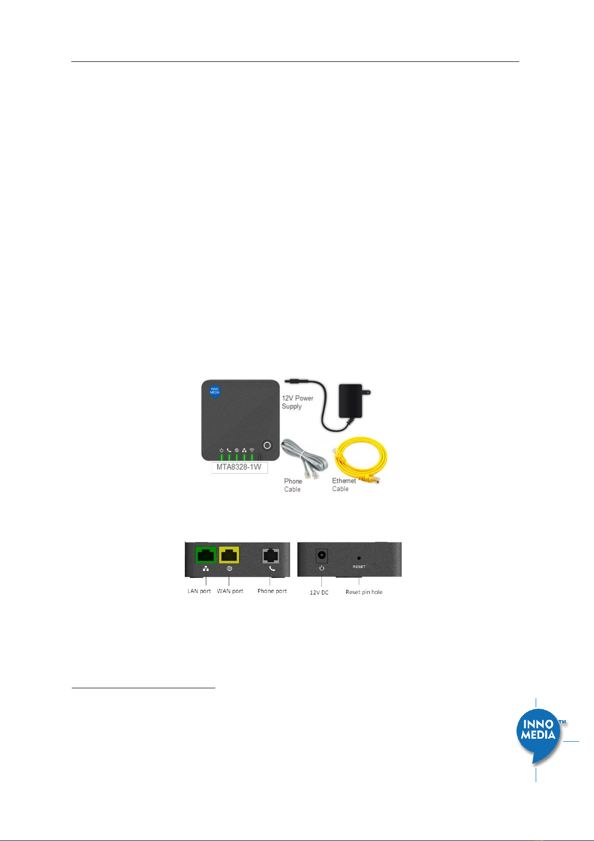
1.2 Package Contents
1.2.1 Residential models: MTA8328-1N, MTA8328-1W, MTA8328-1NP, MTA8328-1WP, MTA8338-1N
•MTA8328-1W(P): Supports WiFi and Ethernet interfaces
•MTA8328-1N(P): Supports Ethernet interfaces only
•MTA8338-1N(P): Supports Ethernet interfaces only
Figure 1. Residential MTA Package
Figure 2. MTA8328-1N Front and back panel (Example)
1
WiFi functionality is supported on certain models only.
InnoMedia MTA8000 Series Administrative Guide
Page 9
Copyright © 2022 InnoMedia. All rights reserved.
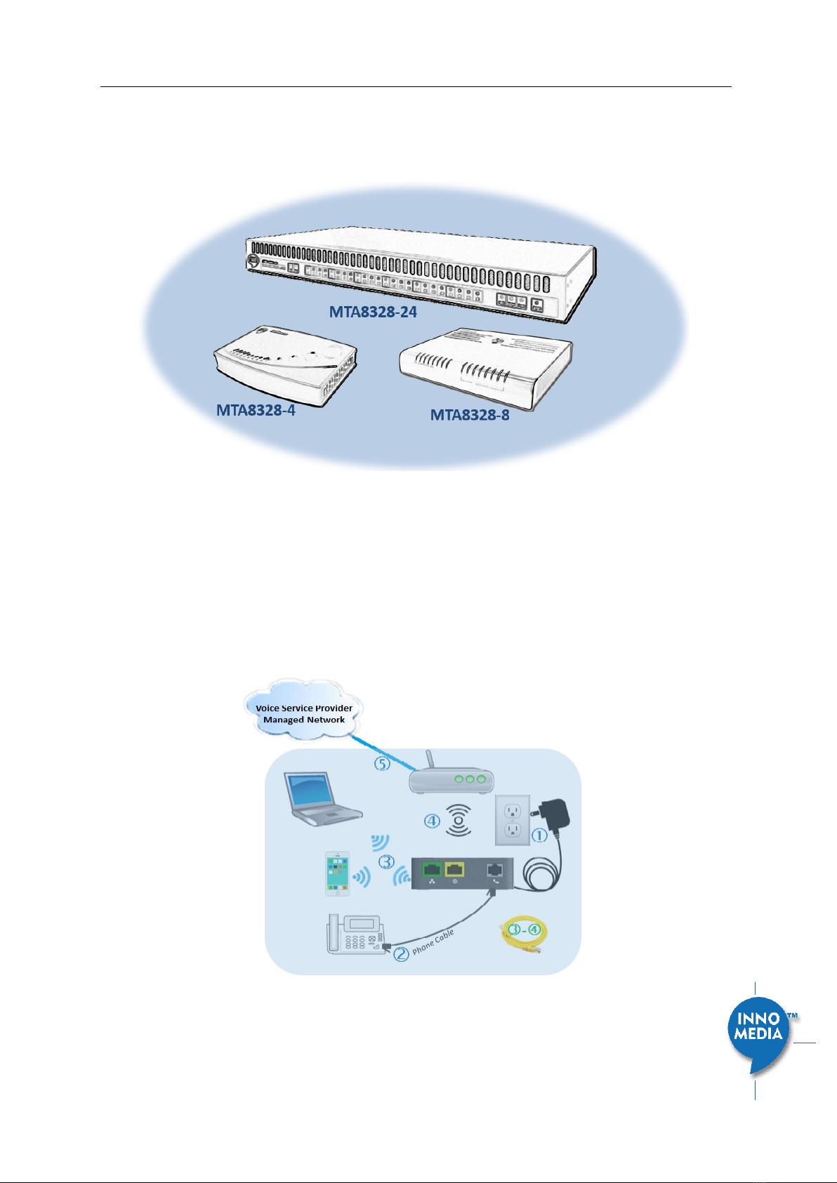
1.2.2Business Models MTA8328-MP: MTA8328-4, MTA8328-8, MTA8328-24
The MTA 8328-MP high density port models (4, 8, 24 FXS ports) allow the use of an Ethernet interface to
connect to the office Router/Firewall.
Figure 3. MTA8328-MP business models (4, 8, and 24 FXS port models)
1.3 Residential Models: Out of the Box Setup
This section provides a step-by-step guide to install the MTA and setup the system for connecting to a
broadband network. Before starting the Installation, make sure your broadband Internet access device is
powered on and your connection is up. (Check your Internet service provider’s documentation).
Note that the Ethernet connection setup applies to MTA8338-1N, MTA8328-1N and MTA8328-1W models;
whereas the WiFi connection setup applies to MTA8328-1W only.
Figure 4. Setup the Residential MTA device to connect to the router or network switch

InnoMedia MTA8000 Series Administrative Guide
Page 10
Copyright © 2022 InnoMedia. All rights reserved.
Plug the supplied power adapter into the MTA. The power LED will show steady green.
Connect your phone into the PHONE port on the MTA using the supplied Phone Cable.
Setup the MTA to connect to your Home Router.
•For Ethernet Connection. If your MTA is located close to your Home Router, connect the yellow
Ethernet cable (supplied) into the WAN port on the MTA and connect the other end into an available
Ethernet port on your router or LAN network. Then proceed to step directly.
•For WiFi Connection. Alternatively, connect the MTA to the Home Router through a WiFi connection.
You will connect the MTA to a WiFi Access Point using your smartphone, tablet or PC. Press the round
button on the top of the unit for about 5 seconds, the MTA will switch to “Setup Mode” and the WiFi
LED will change to solid yellow. Connect your smartphone or PC to the MTA’s preset SSID shown on
the back of the unit, i.e., MTA8328-xxxxxx, product name followed by the last 6 digits of MAC
address. The MTA welcome portal web page will show up on your smartphone/PC. If this page does
not popup, open a web browser and type in the following address: http://192.168.199.1/wifisetup/
During setup, follow the instructions on the welcome portal. You will need to select the WiFi SSID of
your WiFi Access Point and input the WiFi passphrase. For detailed instructions, please see Appendix
C: WiFi Connection Setup through Captive Portal.
Confirm that the MTA is successfully connected to the Home Router and acquires an IP address as follows:
For Ethernet Connection. The WAN LED shows green for 100BT connection, or shows amber for 10BT.
For WiFi Connection. The WiFi LED shows green. If it is not green, repeat step .
Once the MTA connects to the voice service provider network, and completes the registration and service
provision process, you should see a solid green PHONE LED light displayed.
1.3.1MTA8328-1W WiFi Connection Optimizer (WCO) Test
This feature applies to the MTA8328-1W only. The WCO test is designed to determine an ideal location for
the MTA by performing voice quality validation thru a WiFi connection
2
. One of the following results will be
displayed/announced after the WCO test is completed:
Your device location is Excellent|Good|Not Good
If the test result is “Not Good”, one or more of the following steps are recommended before running the
WCO test again until the result is “Good” or “Excellent”:
•Change the location of the MTA. Decrease the distance between the MTA and the WiFi router
and/or avoid any large obstructions between the MTA and WiFi router.
•Switch to another WiFi channel.
•Change WiFi frequency between 2.4GHz and 5 GHz to improve reception.
Note:
•The WCO test can only be invoked when the WAN Ethernet is not connected.
•Run the WCO test only when the WiFi LED displays solid green as its initial state.
2
Note that some WiFi routers may drop WCO packets for strict security configurations.

InnoMedia MTA8000 Series Administrative Guide
Page 11
Copyright © 2022 InnoMedia. All rights reserved.
•The WCO test will run for 30 seconds. During a test period, the WiFi LED changes its state to
“blinking yellow” (0.5 sec ON | 0.5 sec OFF).
Execute the WCO test using any of the following three approaches:
Method 1: Dial ***8 from the phone connected to the MTA.
Off hook the phone, dial ***8, and the MTA Interactive Voice Response (IVR) will play “Wireless connection
optimizer test is in progress, please wait…” After the test is complete, the IVR will then announce the test
result, as well as displaying it through its respective LED state, as shown in LED State
Method 2: Double click the round button on the top of the MTA box
Double click the round button on the top of the unit. After the WCO test is complete, the result is displayed
through its respective LED state, as shown in LED State
Method 3: Device administrative WEB console
Login to the MTA administrative web console (Figure 7). Navigate to Telephony > Wireless Connection
Optimizer page, and click the <Start Test> Button. The test result will be displayed on the WEB GUI page
(Figure 5) as well as through its respective LED state, as shown in
Table 1: WCO Result-LED State.
Figure 5. WCO test result
Table 1: WCO Result-LED State. The WCO test result represented through its LED status will stay active for 20
seconds.
Test State
WiFi LED Representation
WCO Initial State
Solid Green
WCO Result State
•Excellent
Solid Green
•Good
Alternates between solid yellow and solid green.
•Not Good
Solid yellow
InnoMedia MTA8000 Series Administrative Guide
Page 12
Copyright © 2022 InnoMedia. All rights reserved.
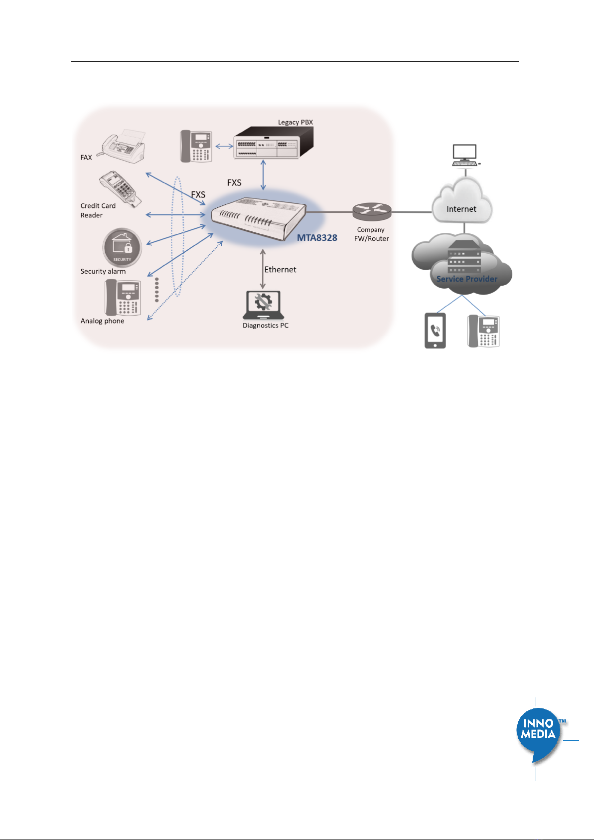
1.4 Business Models: Out of the Box Setup
Figure 6. Setup the MTA in a business environment
Plug the supplied power adapter into the MTA. The power LED will show steady green.
Connect phones or other analog devices into the PHONE X port on the MTA.
Setup the MTA to connect to the Internet. Connect the yellow Ethernet cable (supplied) into the WAN
port on the MTA and connect the other end into an available Ethernet port on your router or LAN
network switch.
Confirm that the MTA is successfully connected to the Router and acquires an IP address. If the WAN LED
shows steady green, it is connected.
•The MTA WAN interface is configured as DHCP client by factory default so that it can obtain an IP
address from the corporate DHCP server.
•When a static IP address is needed, refer to section 2 to login to the MTA web console and configure
the WAN interface accordingly.
Once the MTA connects to the voice service provider network, and completes the registration and service
provision process, you should see a solid green PHONE LED light displayed.
1.5 Terminology and Usage
1. The supported character set of the device text input box: 7 bit ASCII.
InnoMedia MTA8000 Series Administrative Guide
Page 13
Copyright © 2022 InnoMedia. All rights reserved.
2HOME -- DEVICE STATES
The MTA can be managed via a Web Browser interface. Once the MTA is connected to the network, connect
a device with a browser to the same router as the MTA WAN interface, or directly connect the device to the
MTA LAN interface. Access and configure the MTA via a Web Browser.
The IP address of the Ethernet LAN interface is 192.168.99.1.
Press ***1 on a phone connected to the MTA and the IP address of the MTA WAN interface will be played
through the telephone handset.
When the Ethernet WAN interface is connected to the Router, the IP address played is always the Ethernet
WAN IP; otherwise, the WiFi WAN IP address will be played if a WiFi connection has been setup.
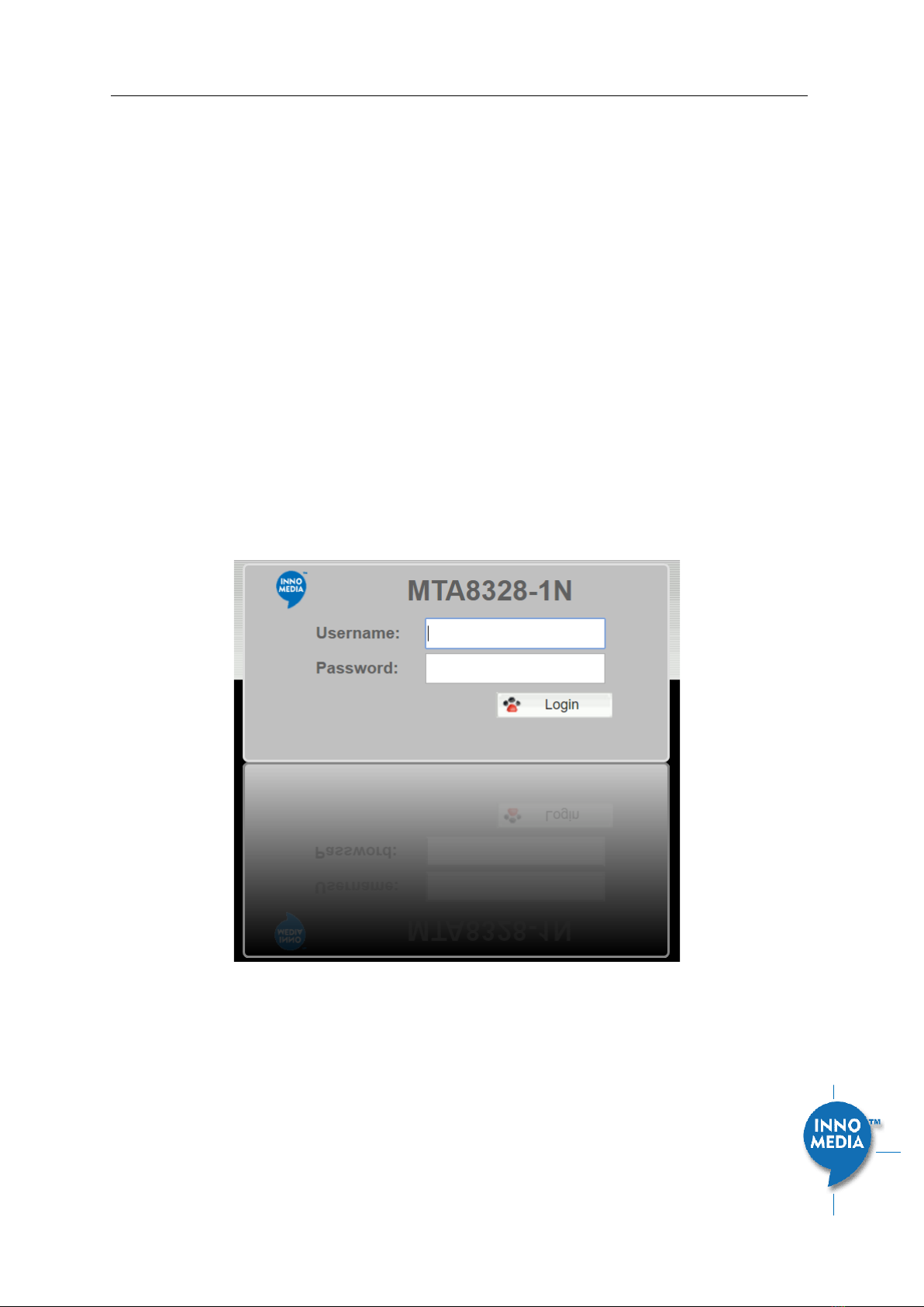
The default Admin Username is: admin
The default Password is: password
The default end user Username is: user
The default Password is: welcome
Note: The username and password could be different if changed by the service provider. They also could be
changed through service provisioning process, Please refer to the user’s guide of provisioning system
provided by specific vendors..
Figure 7. Login Screen - Input Username and Password. MTA8328-1N login screen example.

InnoMedia MTA8000 Series Administrative Guide
Page 14
Copyright © 2022 InnoMedia. All rights reserved.
The Home page displays the MTA current status.
Figure 8. Current status of MTA8328-1N (as an example)
Field Name
Description
Channel
Information
Number of phone lines provisioned
Number of SIP accounts provisioned
Reg Status
Successfully REGISTERED with SIP proxy
Not REGISTERED with SIP proxy
Account disabled
State
Phone on hook
Phone off hook
System
Information
•MAC address of Ethernet WAN
•Provision Status: last provisioning date-
time and status
•Date Time: current date and time
•System Up Time: up time since last
power up.
Version
Information
•Hardware Version
•Firmware Version
•Boot Loader Version
Network
Information
•Master Interface Information: Current
active (in use) network.

InnoMedia MTA8000 Series Administrative Guide
Page 15
Copyright © 2022 InnoMedia. All rights reserved.
•DNS Server: all DNS server IP addresses
configured on the MTA devices. The
priority order of DNS servers (in order of
decreasing priority) used is: Master DNS
server(s) > those obtained from the
DHCP server > user configured DNS
server(s). See section 3.1.7 for details
on Master DNS.
•Domain Name: the domain name
obtained from DHCP Option 15 or the
configured value described in section
3.1.5. The value obtained from DHCP
has higher priority than any manually
configured domain name.
InnoMedia MTA8000 Series Administrative Guide
Page 16
Copyright © 2022 InnoMedia. All rights reserved.
3NETWORK
The Network pages allow the configuration of the MTA network parameters.
3.1 IP Address Configuration for MTA
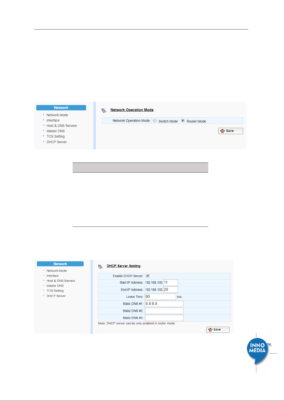
3.1.1Network Operation Mode
This setting is applicable to MTA8328-MP series models only.
Figure 9. Configure the Operation Mode
Field Name
Description
Network Operation
Mode
•Switch Mode, the factory default
setting. The MTA LAN ports are switch
ports. Hosts connect to the LAN ports
have the same IP network as the MTA
WAN interface.
•Router Mode. The MTA provides NAT
and DHCP Server services to hosts which
connect to its LAN ports.
3.1.2DHCP Server Setting
This setting is only applicable to the MTA8328-MP series model, and when the Network Operation Mode is
configured as “Router Mode.”
Figure 10. Configure the DHCP Server
InnoMedia MTA8000 Series Administrative Guide
Page 17
Copyright © 2022 InnoMedia. All rights reserved.
Field Name
Description
Enable the DHCP
Server
Check to allow the MTA to offer IP addresses
to hosts connect to its LAN port(s)
Start IP Address
End IP Address
Input the start/end IP addresses which the
MTA to offer to its LAN hosts.
The IP network is limited to the subnet with
netmask 255.255.255.0.
The network address is the same as that of
its LAN interface.
Lease Time
Input the IP address lease time offered to
the LAN hosts.
Static DNS #1, #2,
#3
Input the DNS server(s) that the MTA offers
to its LAN hosts.
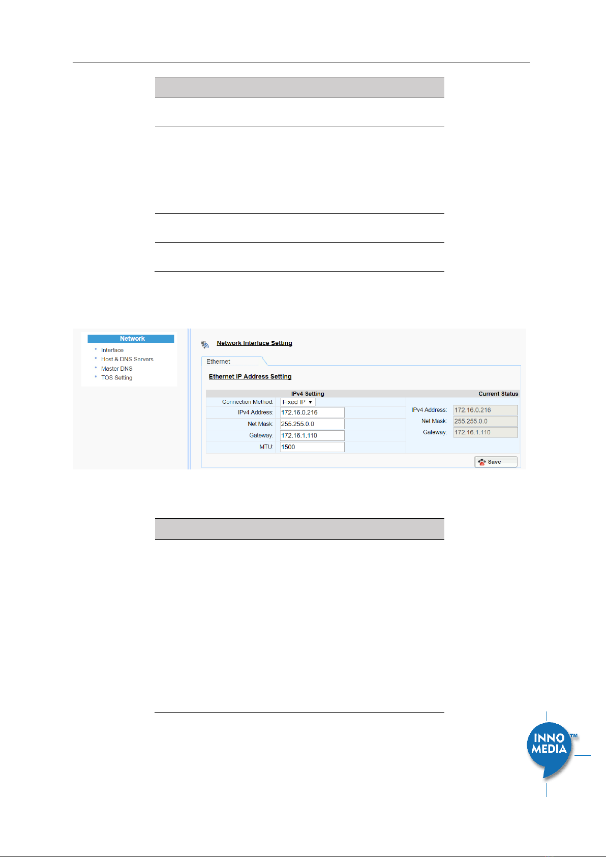
3.1.3Ethernet IP Address Setting
Configure the IPv4 IP address for the device. Click the “Interface” menu from the left panel.
Figure 11. Configuring the IP Address on the Ethernet Interface
Field Name
Description
Connection
Method
•DHCP: Automatically acquires IP address
from the Router.
•Fixed IP: Need to configure the
following parameters according to the
Router network settings.
IPv4 IP address | Net Mask | Gateway |
MTU (maximum size of an IP packet, in
bytes).
Note that default value of MTU is 1500,
and its valid value ranges from 150 to
1500. Do not change the MTU value
unless necessary.

InnoMedia MTA8000 Series Administrative Guide
Page 18
Copyright © 2022 InnoMedia. All rights reserved.
3.1.4WiFi Configuration and IP Address Setting
This page is applicable to the MTA8328-1W model only.
Figure 12. WiFi Configuration and IP Address Setting
Select a WiFi SSID and input the password (Pass Phrase) for WiFi Access Point. Note that the WiFi password
cannot be retrieved from this page by the administrator if it is entered through the Captive Portal page.
3.1.5LAN Interface IP Address Setting
This page is applicable to the MTA8328-MP series models.
Configure the IP address and netmask for its LAN interface. Note that all LAN port(s) share the same IP
address. For maintaining optimum voice quality, the device should not exceed total (WAN and LAN)
throughput of 40 Mbit/sec.
Figure 13. Configure the LAN IP address
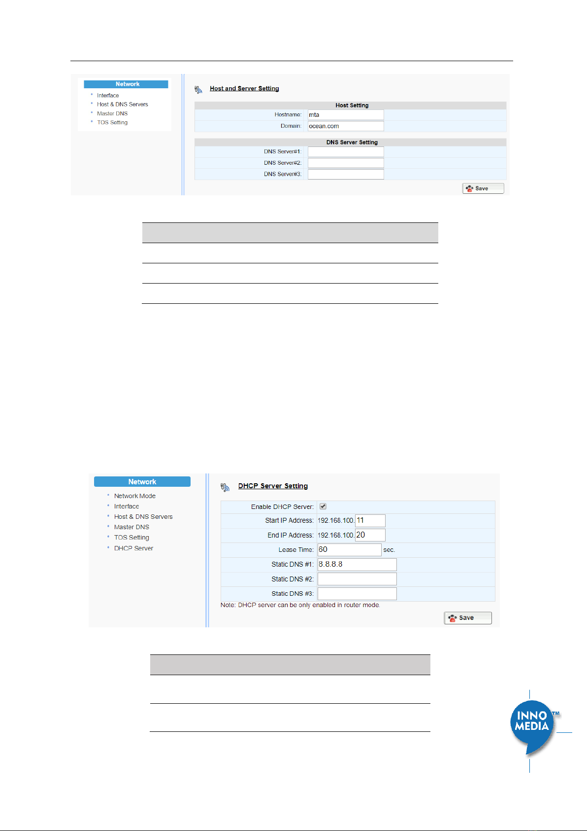
3.1.6Host and DNS Servers
Configure the host and the DNS server information provided by your network operator.
InnoMedia MTA8000 Series Administrative Guide
Page 19
Copyright © 2022 InnoMedia. All rights reserved.
Figure 14. Configuring the host information on the device
Field Name
Description
Host Name
Configure the host name for the device.
Domain
Configure the domain name for the device.
DNS Server Setting
Allows configuration of up to three DNS servers.
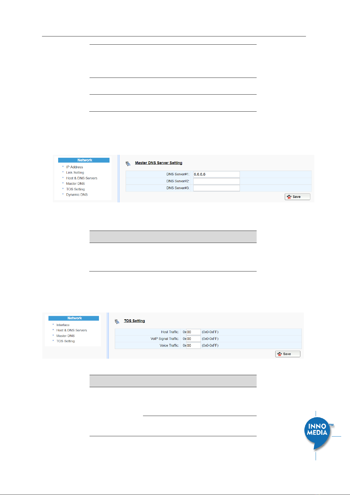
3.1.7 Master DNS
“Master DNS” is the IP address of the domain name server specified by the telephony service provider rather
than the internet service provider. If “Master DNS” is configured, the MTA gets related DNS services from this
configured server to perform voice communication functions. The MTA acquires DNS information from the
following servers in the priority shown (in order of decreasing priority):
1. Master DNS
2. DHCP Option (this is a DHCP Server Setting
3. This setting is only applicable to the MTA8328-MP series model, and when the Network Operation
Mode is configured as “Router Mode.”
Figure 10. Configure the DHCP Server
Field Name
Description
Enable the DHCP
Server
Check to allow the MTA to offer IP addresses
to hosts connect to its LAN port(s)
Start IP Address
End IP Address
Input the start/end IP addresses which the
MTA to offer to its LAN hosts.
InnoMedia MTA8000 Series Administrative Guide
Page 20
Copyright © 2022 InnoMedia. All rights reserved.
The IP network is limited to the subnet with
netmask 255.255.255.0.
The network address is the same as that of
its LAN interface.
Lease Time
Input the IP address lease time offered to
the LAN hosts.
Static DNS #1, #2,
#3
Input the DNS server(s) that the MTA offers
to its LAN hosts.
4. Ethernet IP Address Setting
4. )
5. Manually configured DNS (see section 3.1.5)
Figure 15. Configuring the Master DNS Information
Field Name
Description
DNS Server
Configure the DNS server information
specified by the VoIP service provider for up
to 3 DNS servers.
3.1.8TOS Setting
TOS (Type of Service) is a part of the IPv4 header which is used for precedence, or in other words categorizing
traffic classes. The higher the value of the IP Precedence field, the higher the priority of the IP packet.
Figure 16. TOS Setting
Field Name
Description
TOS Setting
Host Traffic: Use the configured TOS value to
tag data traffic other than SIP or RTP
packets.
VoIP Signal Traffic: Use the configured TOS
value to tag SIP signaling packets.
This manual suits for next models
9
Table of contents
Other InnoMedia Telephone System manuals


