Xblue Networks X16 User manual

X16 Installation Guide
- 64 -
Index
XBLUE Networks © Copyri
g
ht 2007
XBLUE Networks
X16
Installation Guide

X16 Installation Guide
- 2 -
Part Numbers
Revision Table
Revision Description of Changes Date Released
Preliminary Release – PAL 11/2007
Page 6 – added a page brake to change the page tab labels.
Page 12 – Fixed typo in Installation
Page 14 – Fixed typo line up to lineup
Page 16 – Fixed typo in Cable Pair
Page 20 – Fixed typo on endpoint device
Page 35 – Fixed typo, added a “,” to sentence
Page 22 – Entered new LIU functionality
Page 29 – Fixed typo in Muted Ring
Page 29 – Fixed typo in New Message Playback
Page 32 – Fixed typo in Transfer
Page 56 – Fixed typo in One Touch Record
Page 57 – Fixed typos in Using AME
1/14/08
Part Numbers
Part Numbers Description
1610-00 X16 Voice Server
1630-00 2 CO Line Expansion Module
1680-00 SIP VoIP Module
1670-00 Backlit digital telephone endpoint – Charcoal
1670-92 Backlit digital telephone endpoint – XBLUE
1670-86 Backlit digital telephone endpoint – Titanium Metallic
1670-76 Backlit digital telephone endpoint – Red Mahogany
Reproduction, publication, or duplication of this manual, or any part thereof, in any
manner, mechanically, electronically, or photographically, is strictly prohibited.
© Copyright 2006 by XBLUE Network, LLC. All rights reserved.
The information contained in this document is subject to change without notice and should
not be construed as a commitment by XBLUE Networks, LLC,; XBLUE Networks, reserves
the right, without notice, to make changes to equipment design as advances in engineering
and manufacturing methods warrant.
Trademarks: XBLUE, XBLUE Networks, X16 are trademarks of XBLUE Networks, LLC. All
trademarks are the property of their respective owners.
- 63 -
Index
Pulse Dialing, 32
Punch down, 17
—R—
Record, 42, 52
Redial, 42, 52
Redial Button, 30
Remote Access, 60
Remote Commands, 60
Reserved, 42
Ring Alert, 31
Ringer Equivalence, 7
Ringing, 51
Audible Indication, 31
Visual Indication, 31
Ringing Scenarios, 51
RJ11 connector, 14
RJ11 extension, 13
Room Monitor, 31
—S—
Set Relocation, 31
Setting Time and Date, 31
Speakerphone, 31
Speed Dial Bins, 31
Programmable Pause, 30
Speed Key, 42
Star Topology, 13
System Configuration and Layout,
12
System Programming, 50
—T—
Telephone Callouts, 10
Termination Box, 31
Time in Display, 32
Transfer, 32
Direct to Voice Mail, 32
TRK2TRK
Forward, 25
—U—
Underwriters Laboratories, 7
—V—
Voice Mail
Deleting Messages, 58
Getting Started, 58
Operation, 56
Personal Mailbox, 30
Playing New Messages, 57
Quick Start Guide, 58
Voice Mail, 33
Volume
Intercom Forced Tone Ring, 33
Intercom Handset, 32
Intercom Speakerphone, 32
Network Handset, 33
Network Speakerphone, 32
Ringing, 32
Volume Control, 31
Handset, 27
Headset, 27
—W—
Wall Mount, 16

X16 Installation Guide
- 62 -
Index
Programming Steps, 43
Forward, 25
Functions
Cadence, 52
CO Line Cadence, 53
Functions, 52
Intercom Tone Cadences, 52, 53
Phone Book, 52
Ringing Cadence, 53
—H—
Hands-free
Calling, 27
Hands-Free
Calling, 26
Headset, 42, 52
Headset Activation, 27
Hearing Aid Compatible, 7
Hold, 27
Hot Dial Pad, 27
—I—
Idle Display, 55
Installation
CO Line, 14
Expansion Module, 19
Extension Numbering, 18
Location, 13
Telephone Endpoint, 15
Installing the system, 13
Intercom
Intercom Calling, 27
Intercom Paging, 27
Introduction, 9
—L—
Line Access
Dial 9, 24
Line In Use, 27
Line Status Detection, 27
—M—
Meet Me
Paging, 29
Memo Recording, 28, 56
Message Waiting
Telephone Company, 28
Multilingual Extension, 28
Music on Hold, 28
Mute, 29, 42, 52
Muted Ringing, 29, 31
—N—
Navigation Keys, 29, 36
New Message Play, 29
—O—
One Touch Record, 24, 57
One-Way Paging, 29
—P—
Page
All Call, 29
Paging
Meet Me, 29
Part Numbers, 2
Password
Default, 45
Pause, 29, 42, 52
Personal Mailbox, 56
Phone Book Dialing, 30
Phone Setup, 49
Power up and Initialization, 18
Privacy Release, 30
Programmable Buttons, 30
Programmable Pause
Speed Dial Bins, 30
Programming, 35
Feature Buttons, 30, 42
Phone, 35
Phone Setup, 37
System, 35
System Setup, 45
-3-
Table of Contents
Table of Contents
PART NUMBERS ........................................................................2
TABLE OF CONTENTS................................................................3
NOTICES ..................................................................................7
HEARING AID COMPATIBILITY: ....................................................7
UL/CSA SAFETY COMPLIANCE: ....................................................7
FCC INFORMATION ...................................................................7
NOTES: ....................................................................................8
INTRODUCTION........................................................................9
FEATURES ................................................................................9
TELEPHONE CALLOUTS ...........................................................10
BACKLIT LCD DISPLAY ............................................................10
BUTTON LAYOUT....................................................................11
SYSTEM CONFIGURATION.......................................................12
INSTALLATION ......................................................................13
Step 1 - Location .................................................................... 13
Step 2 – CO Line Connections .................................................. 14
Step 3 – Telephone Endpoint Connection .................................. 15
PUNCH DOWN ........................................................................17
Step 4 – Power up and Initialization ......................................... 18
Step 5 – Extension Numbering ................................................. 18
EXPANSION MODULE ..............................................................19
Step 1 – Installing the Expansion Module .................................. 19
Step 2 – Insert the Expansion Module....................................... 20
ENDPOINT DEVICE .................................................................20
FEATURE DESCRIPTION ..........................................................21

X16 Installation Guide
- 4 -
Table of Contents
ALL PAGE ...............................................................................21
ANSWERING MACHINE EMULATION .............................................21
AUTO ATTENDANT -VOICE MAIL (STANDARD)...............................21
BACKLIT BLUE LCD DISPLAY .....................................................21
CALL PICK UP.........................................................................22
CALL TIMER ..........................................................................22
CALLER ID AND CALL WAITING CALLER ID (TYPE 1&TYPE 2) .........22
CO LINE BUSY/IDLE STATUS (LED)............................................22
CO LINE RINGING –PER EXTENSION ..........................................23
CONFERENCE (3-WAY) .............................................................23
CONFERENCE –EXPRESS CONFERENCE.........................................23
CONVERSATION RECORDING –VOICE MAIL (STANDARD) .................24
DAYLIGHT SAVINGS –AUTOMATIC (USING CID)............................24
DIRECT CO LINE ACCESS .........................................................24
DIRECT MAILBOX TRANSFER -VOICE MAIL (STANDARD)..................24
DIRECT STATION SELECT –BUSY LAMP (LED) FIELD ......................25
DISTINCTIVE RINGING –RINGER TYPE ........................................25
DONOT DISTURB (DND).........................................................25
FLASH ..................................................................................25
FLASH TIMER.........................................................................25
FORWARD .............................................................................25
HANDS-FREE CALLING .............................................................26
HANDSET/HEADSET VOLUME CONTROL ........................................27
HEADSET ACTIVATION .............................................................27
HOLD...................................................................................27
HOT DIAL PAD .......................................................................27
INTERCOM CALLING.................................................................27
INTERCOM PAGING..................................................................27
LINE STATUS DETECTION (LINE IN USE) ......................................27
MEMO RECORDING -VOICE MAIL (STANDARD)..............................28
MESSAGE WAITING (TELEPHONE COMPANY-FSK)...........................28
MULTILINGUAL DISPLAY PER EXTENSION ......................................28
MUSIC ON HOLD INPUT............................................................28
MUTE WITH LED INDICATION ....................................................29
- 61 -
Index
Index
—A—
All Call
Paging, 29
All Page, 21, 42, 52
Answering Machine Emulation, 21,
57
Auto Attendant, 21, 56
Off, 51
On, 51
Auto Mute, 26
—B—
Backlit Blue LCD Display, 21
Backlit Display, 21
Backlit LCD Display, 10, 22
Bridge Tap, 15, 20
—C—
Cable Pair Colors, 16
Cable Run, 13
Call Forward, 25
External, 26
TRK2TRK, 25
Voice Mail, 25
Call Time, 22
Call Transfer
Extension, 32
Caller ID
Call Waiting Caller ID, 22
Setting Time and Date, 31
Calling
Hands-free, 27
Character Input Keyboard, 41
CO Line
Busy, 22
Idle, 22
Ringing, 23
Common Ringing, 51
Conference, 23, 42, 52
Express Conference, 30
Operation, 23
Conversation Record, 24
—D—
Daylight Savings, 24
Default Button Layout, 11
Direct Mailbox Transfer, 24
Direct Station Select, 25
Distinctive Ring Tone, 25
Distinctive Ringing, 25
DND, 25, 42, 52
Do Not Disturb, 25
DSS
DSS, 25
DSS/BLF Key, 42
DTMF Dialing, 32
—E—
Expansion Module
Installation, 19, 20
Installing, 19
Express Conference, 23
Conference, 30
Extension Numbers, 15
External
Call Forward, 26
—F—
FCC Registration, 7
Feature Button
Programming, 30, 42
Feature Key, 42
Features, 9
Flash
CO Line, 25
Flash Key, 42
Flash Timer, 25
Key, 52
Flexible Button

X16 Installation Guide
- 60 -
V
oice Mail
Operation
Remote Commands
Mailboxes may be accessed from outside of the system using a telephone with
standard DTMF (Touchtone®) dialing.
Remote Access
Call into the system and let the Auto Attendant answer the call and then dial the
desired extension number. If the extension is forwarded to voicemail, and the
mailbox answers, enter the “Remote Access code” (default remote access code is
123) which is programmed in the “Phone Programming Area”.
Once connected remotely, the system will prompt the user through the remote
control menu.
Replay Previous Message
Play All New Messages
Play All Messages
Skip to Next Message
Record Memo
Stop
Play Personal OGM
Repeat this Menu
** - Erase Playing
Message
Transfer to Auto
Attendant
-5-
Table of Contents
MUTED RING (RING ALERT)......................................................29
NAVIGATION KEYS ..................................................................29
NEW MESSAGE PLAYBACK -VOICE MAIL (STANDARD) .....................29
PAGING ................................................................................29
MEET MEANSWER (PAGING).....................................................29
PAUSE..................................................................................29
PERSONAL MAILBOX -VOICE MAIL (STANDARD) ............................30
PHONE BOOK DIALING .............................................................30
PRIVACY (PRIVACY RELEASE).....................................................30
PROGRAMMABLE BUTTONS (12) .................................................30
PROGRAMMABLE PAUSE (SPEED DIAL BINS)..................................30
REDIAL (LAST 6NUMBER REDIAL) ..............................................30
RING ALERT (MUTED RINGING) .................................................31
RINGING (AUDIBLE AND VISUAL)................................................31
RINGER VOLUME CONTROL .......................................................31
ROOM MONITOR.....................................................................31
SETTING TIME AND DATE (AUTOMATIC).......................................31
SPEAKERPHONE (DIGITAL TELEPHONE ENDPOINT)WITH LED ...........31
SPEED DIAL BINS ...................................................................31
SET RELOCATION....................................................................31
TIME IN DISPLAY ....................................................................32
TONE/PULSE .........................................................................32
TRANSFER.............................................................................32
TRANSFER –DIRECT TO VOICE MAIL...........................................32
VOLUME ADJUSTMENTS ............................................................32
VOICE MAIL (STANDARD) .........................................................33
PROGRAMMING ......................................................................35
NAVIGATION KEYS .................................................................36
PHONE SETUP ........................................................................37
PROGRAMMING FEATURE BUTTONS .............................................42
FEATURE BUTTON PROGRAMMING...............................................43
SYSTEM SETUP.......................................................................45

X16 Installation Guide
- 6 -
Table of Contents
PROGRAMMING GUIDE ...........................................................49
RINGING SCENARIOS..............................................................51
AUTO ATTENDANT ..................................................................51
Auto Attendant On-AA Ring Only.............................................. 51
Auto Attendant Off-AllEXT Ring ................................................ 51
Ringing .................................................................................. 51
FUNCTIONS............................................................................52
Features and LED function....................................................... 52
Lamp (LED) Cadence............................................................... 52
Lamp (LED)s on Phone............................................................ 52
Intercom Tone cadences ......................................................... 52
CO Line Cadence and Status Table ........................................... 53
Ringing Cadence..................................................................... 53
Cable Specifications ................................................................ 53
TROUBLESHOOTING ...............................................................54
IDLE LCD DISPLAY..................................................................55
VOICE MAIL OPERATION.........................................................56
AUTO ATTENDANT ..................................................................56
PERSONAL MAILBOX ................................................................56
Memo Recording..................................................................... 56
One Touch Record .................................................................. 57
Answering Machine Emulation (AME) ........................................ 57
Playing New Messages ............................................................ 57
Deleting Messages .................................................................. 58
Voice Mailbox Quick Start Guide ............................................... 58
Getting Started:...................................................................... 58
REMOTE COMMANDS ..............................................................60
INDEX ....................................................................................61
- 59 -
Voice Mail
Operation
Use the up or down navigation buttons to scroll through the programming
choices, Press the center navigation button to select the “VoiceMail Setup”
parameter.
Use the up or down navigation buttons to scroll through the programming
choices, Press the center navigation button to select the “Personal OGM”
parameter.
Press the center navigation button to select “Play” to listen to the current
message.
To change the message use the down navigation button to scroll to
”Re-Record“ and press the center navigation button, and lift the handset to
begin recording.
Press the center navigation button again to “Stop” the recording, and preview
the newly recorded message.
Hang up the handset to accept the new message or select “Re-Record” to
rerecord the Outgoing Message.
AUTO MUTE
ÆPersonal OGM
Clear My VMSG

X16 Installation Guide
- 58 -
V
oice Mail
Operation
xEach message is automatically saved after it has been played. To scroll
through saved messages, use the left and/or right navigation keys.
Notes:
1) Messages will play in order that they are received.
2) While a message is playing, use the up or down navigation key to scroll
through Pause, Volume, and Exit. Press the select navigation button to
select, the desired action.
3) While a message is playing and the left navigation key is pressed, the
previous message will be played, or if it is the first message, the
message will be repeated.
4)
While a message is playing and the right navigation key is pressed, the
next message will be played. However, if it is the last message in the
list, a prompt will be played, “End all Messages”.
Deleting Messages
After listening to a message, it will automatically be saved in the voice mailbox.
To delete the message, press the “Delete” button twice or the “Delete” button
and the center Navigation Key while the message is playing. The voice mail
message will be deleted and the next message will automatically begin to play.
Note:
The message is permanently deleted and cannot be recovered. If an extension is
unplugged for more than 120 seconds, all of voice mail messages for that
extension will be deleted.
Voice Mailbox Quick Start Guide
Although each voice mailbox comes with a prerecorded outgoing message,
recording a new outgoing message is a nice way to personalize the way the
mailbox answers incoming calls.
Getting Started:
Personal Outgoing Messages are accessed in the voice mailbox area under the
“Phone Programming” Parameter.
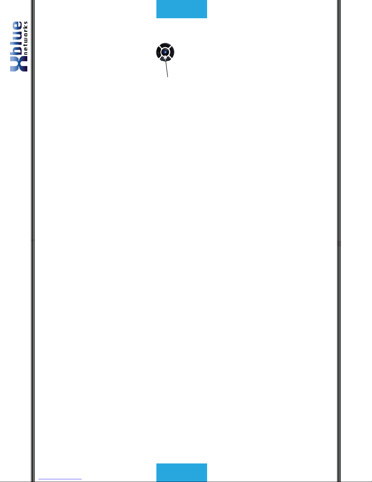
With your handset on hook...Press the “Programming” button to enter the
programming mode, and then Press the center navigation button to access the
Phone Setup area.
AUTO MUTE
ÆPhone Setup
System Setup
-7-
Notices
Notices
Hearing Aid Compatibility:
The digital telephone endpoints are hearing aid compatible, as defined in section 68.316 of Part 68 FCC
Rules and Regulations.
UL/CSA Safety Compliance:
The X16 system has met all safety requires, and found to be in compliance with the Underwriters
Laboratories (UL) 60950-1.
Warning: This service information is designed for experienced repair technicians only and is not
designed for use by the general public. It does not contain warnings or cautions to advise non-technical
individuals of potential dangers in attempting to service a product. Products powered by electricity
should be serviced or repaired only by experienced professional technicians. Any attempt to service or
repair the product or products dealt with in this service information by anyone else could result in
serious injury or death.
This equipment generates, uses, and can radiate radio frequency energy, and if not installed and used
properly, that is, in strict accordance with the instruction manual, may cause interference to radio and
television reception. This equipment has been tested and found to comply with the limits for a Class B
computing device in Subject J of Part 15 of FCC Rules, which are designed to provide reasonable pro-
tection against such interference. However, there is no guarantee, or warranty, that interference will not
occur in a particular installation. If this equipment causes interference or fails to operate correctly, due
to radio frequency interference (RFI) or electromagnetic interference (EMI), it will be fixed at the
owners’ expense.
FCC Information
Provide the following information to the Telephone Company prior to connection the X16 system to the
network.
Item Specification
FCC Registration D6XKH05BX16
Ringer Equivalence 0.5B
Networks Address Signaling E
Service Order Code 9.0Y
Facility Interface Code 02LS2
Required Network Interface RJ11 & RJ14

X16 Installation Guide
- 8 -
Notes:
Notes:
- 57 -
Voice Mail
Operation
One Touch Record
While speaking to an outside party, the user may press their record button and
record the current conversation. The message will be saved as a new voice mail
message in the user’s personal mailbox.
Answering Machine Emulation (AME)
This feature “Mimics” the call screening feature of an answering machine. Five
seconds after a call is answered by an extension users’ voice mailbox, that user
can monitor/screen the caller as they leave a message.
The extension user will receive a warning tone, which indicates that a caller has
been answered by their voice mailbox. The user has the option to monitor the
call, or ignore the alert, and allow the caller to leave a message. Once the user
has selected to monitor the caller, they have the option to leave the caller
undisturbed (leaving a message) or to retrieve the caller from the voice mailbox
and be connected to the caller for a live conversation.
Using AME
xThe extension must be forwarded to Voice Mail.
xThe Telephone Company Central Office Line may be transferred directly
into the user’s voicemail box, or transferred and ring at the extension
until it is forwarded to voice mail.
xIf a call is transferred to an extension or directly into the users’ voice
mailbox, AME is available once the Line button turns green. The
extension user may press the center navigation button to monitor the
message being left.
xLift the handset to speak live to the calling party.
xPress the left or right navigation button to exit the AME without
intercepting the call.
Playing New Messages
The center navigation button will flash when you have a new voice mail
message. In addition, the display will indicate how many new voice mail
messages you have.
To access your voice mailbox:
xFrom an idle telephone
oPress the center navigation key. (No password required)
oThe voice mail count will be announced
oThe time and weekday will be announced
oThe messages will play in the order that they are received.

X16 Installation Guide
- 56 -
V
oice Mail
Operation
Voice Mail Operation
The System comes equipped with a 4 channel auto attendant and voice
mail system, which can answer up to 4 different calls simultaneously.
Auto Attendant
The system can be programmed to answer in “Auto Attendant” mode.
When Auto Attendant is set to “On-AA Ring Only” the attendant
telephone will ring unit the “Waiting Time” expires. When Auto
Attendant is set to “Off-AllEXT Ring” all telephone programmed to
ring will ring until the “Waiting Timer” expires. Once the Auto Attendant
answers the caller may dial the desired extension number.
Personal Mailbox
Each extension is automatically assigned a personal mailbox, which is used to
play a personal greeting and record message. In addition, all extensions are
automatically forwarded to their mailbox.
Once forwarded to voice mail the center navigation key will be lit solid, indicating
that the telephone has been forwarded to voice mail. Be sure to record the OGM
so that callers will receive your personal message. Once forwarded, all calls that
are transferred to that extension will be forwarded to the user’s personal mailbox
and will hear their OGM (Outgoing Message).
Memo Recording
Each extension can press their record button to record a memo or a conversation
that is taking place in the office.
1) Press the record button
2) Press the center navigation button to begin, and end recording.
3) The memo will be stored as a new message.
AUTO MUTE
Record Memo
Yes?
AUTO MUTE
Record Memo
Stop
-9-
Introduction
Introduction
The X16 system is a full featured, next generation, multi-line business
telephone system ideal for both home and small office environments. It
comes equipped to interface with 4 Central Office (CO) Lines, equipped to
receive Caller ID, and sixteen (16) proprietary digital telephone endpoints.
The system can be expanded to accommodate an additional two (2) CO
Lines, allowing a maximum configuration of six central office telephone lines.
Or the system may be configured with 4 CO Lines and 2 Voice over IP (VoIP)
Session Initiation Protocol (SIP) Media Gateways and sixteen proprietary
digital telephone endpoints. In addition, the system comes standard with
Auto Attendant and all digital telephone endpoints have a personal digitally
integrated voice mailbox.
Features
Auto Attendant Intercom Pa
g
in
g
Answerin
g
Machine Emulation Meet me Answer (Pa
g
in
g
)
Audible and Visual Rin
g
in
g
Memo Recordin
g
Backlit LCD Display Messa
g
e Waitin
g
(Telco-FSK)
Call Timer Multilin
g
ual Display per Extension
Call Transfer Music on Hold Internal/External
Caller ID and Call Waitin
g
Caller ID Mute with LED indication
CO Line Busy/Idle Status (LED) Navi
g
ation Keys
CO Line Rin
g
in
g
(pro
g
rammable) New/All Messa
g
e Play
Conference (3-way) Voice Mail
Conversation Recordin
g
Phone Book Dialin
g
Dayli
g
ht Savin
g
s (Automatic with
Caller ID)
Pro
g
rammable Buttons (12)
Direct Mailbox Transfe
r
Pro
g
rammable Pause (Speed Bins)
Direct Station Select
–
Busy Lamp
Field
Redial
Display Number Dial Remote Messa
g
e Pickup
Distinctive Rin
g
in
g
Rin
g
er Volume Control
Do Not Disturb Set Time and Date
Flash Timer Speakerphone with LED
Handset/Headset Volume Control Speed Dial Buttons
Headset Activation Time in Display
Hold Tone/Pulse
Intercom Callin
g
Voice over IP (VoIP) - future

X16 Installation Guide
- 10 -
Telephone Callouts
Telephone Callouts
Backlit LCD Display
Time, Date and Da
y
Line Ke
y
s
Pro
g
ram Ke
y
Caller ID Lo
g
Phone Book
New Voicemail Extension
Number
Integrated
Headset
Backlit Display
Navi
g
ation Ke
y
s
Programmable
K
e
y
s
Speakerphone Button
- 55 -
Idle LCD Display
Idle LCD Display
07:19P 10/12 FRI
Accounting 312
07:19P 10/12 FRI
New CID:24 312
07:19P 10/12 FRI
NEW VMSG:04 312
07:19P 10/12 FRI
TRK2TRK FWD 312
07:19P 10/12 FRI
External FWD 312
07:19P 10/12 FRI
Accounting DND
Time, Date, Day, Name and Number In DND Mode
4 New Voice Mail Messa
g
es 24 New Caller ID Calls
Trunk to Trunk Forwarding External Forwarding

X16 Installation Guide
- 54 -
Troubleshooting
Troubleshooting
Trouble Possible Causes Action
The Blue LED “Heartbeat”
is not functioning.
AC Cord or Power adaptor
is not working correctly or
not plugged in correctly.
Remove all of the plugs and
re-plug them back in.
Sluggish Performance at
Key Telephone –
xPress Speakerphone
several time with no
reaction
xLift/Replace Handset
with no reaction
Cable Pairs connect to one
or more KSU digital ports
without a telephone
connected
xRemote Connection of
un-terminated cable pair
at KSU port
xInstall telephones at all
locations wired
Telephone LCD Shows:
“No Link to KSU”
Cable Pairs Connected to
one or more KSU digital
ports without telephone
installed
xRemove connection of
un-terminated cable
pairs at the KSU.
xInstall telephone at all
locations which are
wired.
Telephone reports:
“Register Fail” or cycles
between “Register Fail”
and “Initializing, Please
Wait!”
Cable pairs connected to
one or more KSU digital
ports without a telephone
connected.
xRemove connection of
un-terminated cable
pairs at the KSU.
xInstall telephone at all
locations which are
wired.
One or more extensions
are experiencing static or
distortion.
Not all extensions are
punched down.
xRemove connection of
un-terminated cable
pairs at the KSU.
xInstall telephone at all
locations which are
wired.
- 11 -
Button Layout
Button Layout
Navigation keys
Scroll left or right, up and down to update the LCD Display.
OK
/
Select
/
Confirm
Voice Mail Access
Scroll Up
Scroll Down
Bac
k
u
p
a level
Scroll Left Scroll Ri
g
ht
CO Lines with
Integrated
CID
Programmable
Feature Buttons
Delete, Conference, Feature,
Transfer, Redial, Hold,
Mute and Speaker
12 Ke
y
Dial Pad

X16 Installation Guide
- 12 -
System
Configuration
System Configuration
The system uses advanced digital interface technology. One cable pair
supports up to four digital telephone endpoints. Each digital telephone
endpoint has its own extension number, and can be called from any
other extension in the system.
- 53 -
Functions
CO Line Cadence and Status Table
Speaker Unlit: Speaker or Intercom Link Idle
Fast: Receiving incoming call
Lit: Talking with the Digital Telephone Endpoint
Slow: In headset mode
Enter/VM Unlit: No New messages
Fast: New Message in VM
Lit: No answer forward active – unanswered calls will be
forwarded to VM
Slow: New Telephone Company Line Message Waiting
Mute Unlit: Inactive – phone is not muted
Lit: Active – phone is muted
All Page
On Flexible Button
Unlit: Inactive – Not currently paging
Lit (rapid flash): Making or receiving a page
DND
On Flexible Button
Unlit: Inactive – DND function is off
Lit (solid): Active – DND function is active
Record
On Flexible Button
Unlit: Inactive – Not recording call
Lit (rapid flash): Active – Recording call
Headset
On Flexible Button
Unlit: Headset function is off
Lit: Headset function is on
DSS/BLF
On Flexible Button
Unlit: The extension programmed on the button is idle
Lit: The extension programmed on the button is busy
Slow: The extension programmed on the button is in DND
Ringing Cadence
CO Ring Synchronized with CO Ringing
Intercom Ringing 0.25 sec on, 0.25 sec off, 0.25 sec on, 1.25 sec off repeating.
Transfer/Recall 1 sec on, 1 sec off, repeating
Hold Reminder 1100Hz, 0.05 sec on/off, 4 beeps
Privacy Release 1100Hz, 0.2 sec on/off, 1 beep
Privacy Recover 1100Hz, 0.2 sec on/off, 2 beep
Call Waiting Beep 500Hz, 0.2 sec on/off, 2 beeps
Single/All Page 600Hz, 1.0 sec on, 1 beep
Confirmation Beep 1100Hz, 0.5 sec on, 1 beep
Warning Beep 1100Hz, 0.05 sec on/off, 3 beeps
Cable Specifications
Category AWG Length Impedance
CAT5e 24 600 feet 20 Ohms

X16 Installation Guide
- 52 -
Functions
Functions
Features and LED function
Feature Code Descriptive LED lit LED Not Lit
Feature + Record Active Not Recording
Feature + Open N/A N/A
Feature + Flash Key N/A N/A
Feature + DND Active Not in DND
Feature + Mute Active Not in Mute Mode
Feature + Conference N/A N/A
Feature + Pause N/A N/A
Feature + Redial N/A N/A
Feature + Headset Active Not Active
Feature + All Page Active Not Active
Feature + Open N/A N/A
Lamp (LED) Cadence
Unlit Off
Lit Lit Solid
Fast 0.125 sec off, 0.125 sec on, repeating
Slow 0.5 sec off, 0.5 sec on, repeating
Wink 1 0.250 sec off, 1.750 sec on repeating.
Wink 2 0.250 sec off, 0.250 sec on, 0.250 sec off, 1.25 sec on repeating
Wink 3 0.250 sec off, 0.250 sec on, 0.250 sec off, 0.250 sec on, 0.250 sec off, 0.750
sec on, repeating.
Lamp (LED)s on Phone
CO Line Status My Station Other Stations
Idle Unlit Unlit
In-Use Lit Green (I-Use) Lit Blue (In-Use)
On Hold Slow Green (I-Hold) Lit Blue (In-Hold)
Ringing Fast Blue Fast Blue
Being Transferred Slow Green (I-Hold) Lit blue (I-Hold and Transfer)
Intercom Tone cadences
Dial Tone Continuous Tone
Busy Tone 0.5 sec on, 0.5 sec off, repeating
Ring Tone 1 sec on, 1 sec off, repeating
DND Tone 0.25 sec on, 0.25 sec off, repeating
- 13 -
Installation
Installation
The X16 comes standard with four RJ11 extension ports. Each port
supports up to 4 proprietary digital telephone endpoints, for a total of
sixteen (16) endpoints. Each port on the system will support up to 600
feet of cable.
In a star topology 600 feet is calculated by adding each Digital
Telephone endpoints cable run.
Cable A + Cable B + Cable C + Cable D <= 600 feet.
In a serial cable topology 600 feet is calculated by adding the distance of
the initial run plus the distance between each telephone.
Cable A to telephone 1 + (distance between telephone1 & telephone 2)
+ (distance between telephone 2 & telephone 3) + (distance between
telephone 3 & telephone 4) <= 600 feet.
Step 1 - Location
The system should be located close to the telephone company interface
(RJ21X), and have a dedicated outlet with an isolated ground.
The system can be mounted on the wall or placed on a table. Once the
location of the system is determined use the supplied wall mounting
template to level and secure, the system, with the provided screws, or
place it on a table.
CO Lines
Extensions
2 Line Expansion
CO or VoIP Module

X16 Installation Guide
- 14 -
Installation
Lineup the back of the system with the four screws, and slides it into
place.
Step 2 – CO Line Connections
Using the matrix below, connect the CO Lines to the system using one
RJ14 connector per CO Line. The port labeled Line 1 is a direct access
auxiliary port for line 1 allowing an analog device direct access.
Line Port Number
AUX CO Line1
CO Line 1 1 / 2
CO Line 2 2
CO Line 3 3 / 4
CO Line 4 4
CO Line 5 5
CO Line 6 6
CO Lines
Extensions 2 Line Expansion
CO or VoIP Module
L4 L3 L2 L1
A
UX CO
CO Lines
- 51 -
Ringing Scenarios
Ringing Scenarios
Auto Attendant
The Auto Attendant can be set to “On-AA Ring Only” or “Off-AllEXT Ring.
Auto Attendant On-AA Ring Only
When set to On-AA Ring Only, only the extension defined as the attendant (301
at default) will ring until the Auto Attendant Delay Timer expires. If the timer is
set to 10 seconds, for example, the attendant extension will ring up to two times
before the auto attendant answers.
Auto Attendant Off-AllEXT Ring
When set to Off-AllEXT Ring, all telephones programmed to ring, will ring until
the Auto Attendant Delay Timer expires.
Ringing
Each extension may be programmed to ring or not ring, depending on the
telephones programming. However, the Auto Attendant must be set to off-AllEXT
Ring, to allow extensions to ring before the auto attendant answers the call. The
telephones will ring unit the Auto Attendant Wait Timer expires, which can be set
from 06 seconds to 240 seconds.
Common Ringing
Auto Attendant Delay - Set the Auto Attendant to Off-AllEXT Ring, and the Auto
Attendant Wait Timer to 30 seconds and all telephones will ring for 30 seconds
and then the line will be answered by the auto attendant.
Auto Attendant Answering – Set the Auto Attendant to On-AA Ring Only, and set
the Auto Attendant Wait timer to 10 seconds. Only the Attendant telephone will
ring, for the length of the timer, and then the Auto Attendant Greeting will begin
to play.

X16 Installation Guide
- 50 -
Programming Guide
System
Programming
Default
Password
“####”
Feature Parameter Sub Parameter
Change
Password
####
Date & Time Year
Month/Date
Time 00:00 format
Recall Time 30-120 seconds
Tone/Pulse Tone, pulse
Flash Time 80-800 milliseconds
Music Source Internal/External
CO MSGW On/Off
Clear CO
MSGW
Yes?/No?
Area Codes Home Area code
Local Area C1
Local Area C2
Local Area C3
Local Area C4
Local Area C5
Mail System Clear All VMSG Yes?/No?
Auto Attend Ring On-AA Ring Only
Off-AllEXT Ring
Attendant Extension 301 Ext
AA Answer Delay 06~240 seconds
Message Length Unlimited
Greeting
1 Minutes
Day Time 09:00 A
Night Time 06:00 P
Day Time OGM
(Outgoing Msg)
Night Time OGM
(Outgoing Msg )
AUX OGM
(Outgoing Msg)
Reset KSU Yes?/No?
- 15 -
Installation
Step 3 – Telephone Endpoint Connection
Connect telephone endpoints to the system using one RJ11 port for up
to 4 different endpoints, with a maximum of 600 feet per port. Once
connected each telephone endpoint will register with the voice server
when it is powered up. At default, the extensions begin with number
301. The remaining extension numbers must be entered. See step 5.
Correct Installation process
It is important to connect a telephone to every jack that is connected to
the system. Extensions connected to a cable with “Bridge Taps”, may
experience distortion. If locating a bridge tap is not practical, a quick
resolution is to use a different cable pair such as the Yellow/Black or
White/Orange.
Extensions
13
~
16
9
~
1
2
5~8
1
~
4

X16 Installation Guide
- 16 -
Installation
Incorrect Installation process - DO NOT leave any ports open:
X16 Cable Pair
White Blue White Orange
Ports 1~4 Ports 5~8
301 302 303 304 305 306 307 308
White Green White Brown
Ports 9~12 Ports 13~16
309 310 311 312 313 314 315 316
Leaving any ports punched down but not connected to a telephone, may
result in erratic operation.
When mounting a Digital Telephone Endpoint be sure to use the inner
posts on an adjustable wall mount plate.
- 49 -
Programming Guide
Programming Guide
Phone Setup Feature Programming Parameter Sub Parameter
Language English, Spanish, French
Feature Key Press feature button
Extension Number 3xx
Auto Mute On/Off (Private/ Hands Free)
Preference Call Intercom
CO Call
Line Selection Line # 1-4
Line # 5-6
Record All Call On/Off
Hold Reminder 30
60
0ff
Ringer On/Off Line1 Ringer – On/Off
Line2 Ringer – On/Off
Line3 Ringer – On/Off
Line4 Ringer – On/Off
Line5 Ringer – On/Off
Line6 Ringer – On/Off
Ringer Type Line1 Ring Type 1-6
Line2 Ring Type 1-6
Line3 Ring Type 1-6
Line4 Ring Type 1-6
Line5 Ring Type 1-6
Line6 Ring Type 1-6
Call Forward Waiting Time
FWD Destination
FWD Phone Number
10 - 25 Seconds
Off
VoiceMail
External
TRK2TRK
Empty
Voice Mail Setup Remote Code
Personal Outgoing MSG
Clear VM messages
Call Screening
123
=On
User Name Empty
Reset Phone Yes?/No?

X16 Installation Guide
- 48 -
System Setup
Day Time – This timer determines when the
system will start to function in day mode.
Night Time – This timer determines when the
system will start to function in the night
mode.
Day Time OGM – This is the message that
will play when the system is in Day mode.
Night Time OGM – This is the message that
will play when the system is in Night mode.
AUX OGM – The Auxiliary Outgoing Message,
is accessed when the caller dials “7” while in
the Auto Attendant. At default this is
intended to be used to record the company
directory. However, it can be used as an
announcement only “mailbox” for commonly
asked questions such as hours of operation
or directions to the office.
Day Time
=09:00A
Night Time
=06:00P
Day Time OGM
Play
Night Time OGM
Play
AUX OGM
Play
- 17 -
Punch Down
Punch Down
In this example, system ports 10 through 16 do not have telephones
connected to them but they are still “punched down” on the system. There is
a potential that extensions, especially extension 309 in this example, may
experience distortion.

X16 Installation Guide
- 18 -
Punch Down
Step 4 – Power up and Initialization
Connect the power to power on the system. To initialize the system,
once the blue LED begins flashing at 1 impulse per second (IPS), switch
the “init switch” back and forth three times and the LED will begin
flashing at rapid rate, for 5 seconds and then return to 1 IPS. For proper
operation, be sure to reset, by unplugging, the system after all
extensions are connected.
Step 5 – Extension Numbering
One extension will automatically be numbers 301 all other extension
numbers will have to be entered at the time of installation. Valid
numbers are 302 to 399. Please refer to Phone Setup (see Page 37), in
the programming section.
The system becomes fully functional after all extensions are registered.
Extensions may be moved from one port to another simply by
unplugging the unit and plugging it into another active port. If the
extension is unplugged for longer than 120 seconds (2 minutes) the port
may initialize, and revert back to factory default – This includes all
personal voice mail settings. Any port that is active must have either a
telephone or an Endpoint Device connected to it, or distortion may be
heard.
Note:
An “Endpoint Device” may be needed when relocating an extension.
Initialization Switch
MOH Por
t
Power Input
- 47 -
System Setup
Mail System – Voice mail comes standard with
the system and only takes a few minutes to
setup.
Clear All VMGS - Select “Yes?” to clear all voice
mail messages in the system. Select “No?” or
press the left navigation key to retain the
messages.
Auto Attend Ring – When set to “Off-AllExt
Ring” all telephones will ring until the AA
answer delay timer expires. When set to “On-
AA Ring Only” only the attendant telephone will
ring and then the call will be answered by the
auto attendant.
Attendant EXT# – This is the extension that will
ring when a caller dials “0” in the auto
attendant.
AA Answer Delay – The Auto Attendant Answer
Delay is the time between a call ringing into the
system and the Auto Attendant answering. The
timer is variable between 06~240 seconds.
Message Length – This setting determines the
maximum amount of recording time available to
callers when leaving a message.
Unlimited – giving no limit to the amount of
time each message can take.
Greeting – A message can only be as long as
the recorded greeting. Callers that try to record
a message longer than the greeting will be
disconnected.
1 Minute – A message recording can only be 1
minute long. Callers that try to record a
message longer than 1 minute will be
disconnected.
AUTO MUTE
Mail System
Clear All VMSG
No?
Auto Attend Ring
=On-AA Ring Only
Attendant EXT#
=301
AA Answer Delay
=10
Message Length
=Unlimited
=Greeting
=1 Minute

X16 Installation Guide
- 46 -
System Setup
Music Source – The system comes with an
internal music on hold source, or can be
connected to an external music on hold source
such as a CD or MP3 player.
CO MSGW – If this parameter is set to “On” and
a Network (Telephone Company) voice mail
system with Message Waiting Indication (MWI)
is being used, then the display will show what
lines have a new voice mail message. On the
second line of the display it will show:
CO MSGW: 12 4 6 – for lines 1, 2, 4 and 6.
Clear CO MSGW – This will erase (clear) all of
the Message Waiting Indication (MWI) left by
the Network (Telephone Company) voicemail
system.
Area Codes – There are a total of 6 area codes
that can be entered into the area code
parameter.
The first is the Home Area Code. This is the
area code of the physical location of the system.
When Caller ID is received, the 3 digits entered
into the “Home Area Code” will not be displayed
or redialed.
The next five “Local Area” codes are used if the
calling area requires ten (10) digit dialing. When
Caller ID matches an entry, the number will be
displayed and redialed with only 10 digits.
When Caller ID does not match an entry in
either the Home Area code or the local area
codes, the system will display and redial the
number with 11 digits.
AUTO MUTE
Music Source
=External
AUTO MUTE
CO MSGW
=Off
AUTO MUTE
Clear CO MSGW
=No?
AUTO MUTE
Area Codes
Home Area Code
Local Area C1
Local Area C2
Local Area C3
Local Area C4
Local Area C5
- 19 -
Expansion Module
Expansion Module
The X16 system comes with four CO Lines and is expandable to six CO Lines.
The two line expansion module can be either a CO Line module or a two channel
VoIP Gateway Module.
The expansion module mounts inside the communication server and connects to
the main board, via ribbon cable. When the system is powered on, the
expansion module will be recognized in software and fully operational. Use the
following steps to install the expansion module.
Step 1 – Installing the Expansion Module
Place the voice server face down on a stable surface such as a table, showing
the four rubber feet.
Remove the four rubber feet, placing them in a safe place, such as the back of
the voice server, exposing 4 screws. Unscrew the four screws and remove the
cover.
2 CO Line Expansion Module
Phili
p
s Head Screws
Rubber Feet

X16 Installation Guide
- 20 -
Endpoint Device
Step 2 – Insert the Expansion Module
Remove the plastic tab found on the front of the Voice server. Insert the RJ14
(RJ48 for VoIP) connections through the front of the voice server and secure the
card with the provided screws. Connect the ribbon cable from the expansion
module to the main board and replace the cover. Place the provided black
plastic encasement window around the newly installed card.
Endpoint Device
Every live telephone jack connected to the system will receive a data signal. If
the system finds an open jack (bridge tap) the data signal may be lost, causing
the remaining digital telephone endpoints to receive erroneous data, which may
lead to improper operation. Therefore, for proper operation each live telephone
jack, connected to the system, must have either a digital telephone endpoint or
an endpoint device.
Symptoms of an open jack include – but not limited to - voice distortion, static
and slow speakerphone reaction when the button is pressed, problems accessing
CO Lines, etc.
- 45 -
System Setup
System Setup
When System Setup is selected, the password will need to be
entered. At default, the password is ####.
The default system password is ,
and can be changed to any 4 digit number.
To set the system date and time:
Enter the Year in two digit year and then press
the center navigation button. Enter the month
and the day in four digit format and then press
the center navigation button. Enter the hour
and the minutes in 12 hour format, and then
press the center navigation button. Press the up
navigation button for P (PM) and the down
navigation button for A (AM).
Note: Caller ID
will maintain the time and date after it is set the
first time.
Recall time – When a call is placed on hold, this
timer begins. When this timer expires, the call
placed on hold, will begin ringing all extensions
in the system. Using the up or down navigation
key, the timer can be adjustable from 30, 45,
60, 90, and 120 seconds.
Tone/Pulse – This allows the system to be used
on older network (Telephone Company) Lines.
DTMF (Touch Tone) Tones are used on most
network (Telephone Company) lines.
Flash – The Flash, which is a momentary
closure, is a rudimentary indication to the
telephone company line that a feature is being
enabled, such as call waiting. This timer is
adjustable from 80 to 800 milliseconds.
AUTO MUTE
Change Password
AUTO MUTE
Date & Time
AUTO MUTE
Recall Time
=30 Seconds
AUTO MUTE
Tone/Pulse
=Tone
AUTO MUTE
Flash Time
=600 ms
Other manuals for X16
10
Other Xblue Networks Telephone System manuals