Innotech GENII MZSAH REM User manual
© MASS ELECTRONICS Pty Ltd 2006
Models:
GENII MZSAH REM: Multi-zone Station Aer Hours
Remote Expansion Module
DS 15.12
August 2013
GENII MZSAH REM
Multi-zone Station Aer Hours
Remote Expansion Module
Applications
Expands GENESIS Controller capabilities by providing a numeric output
display, numerical value input, a single toggle digital input switch and
single LED display output for distributed control via RS485. The GENII
MZSAH REM Module provides a visual display of up to 6 control values
and a means to set up to 6 parameters.
Application Notes
A GENESIS Controller must have version 4 firmware installed to support
REM Modules. Version 4.1 or higher Config Soware must be used to
configure a GENESIS Controller that has REM Modules connected to it.
One GENESIS Controller can have up to 15 GENII MZSAH REM Modules*
connected to it via the REM comms bus.
For detailed connection information to the pre version 5 GENESIS Digital
Controller Family, please refer to DS 99.03
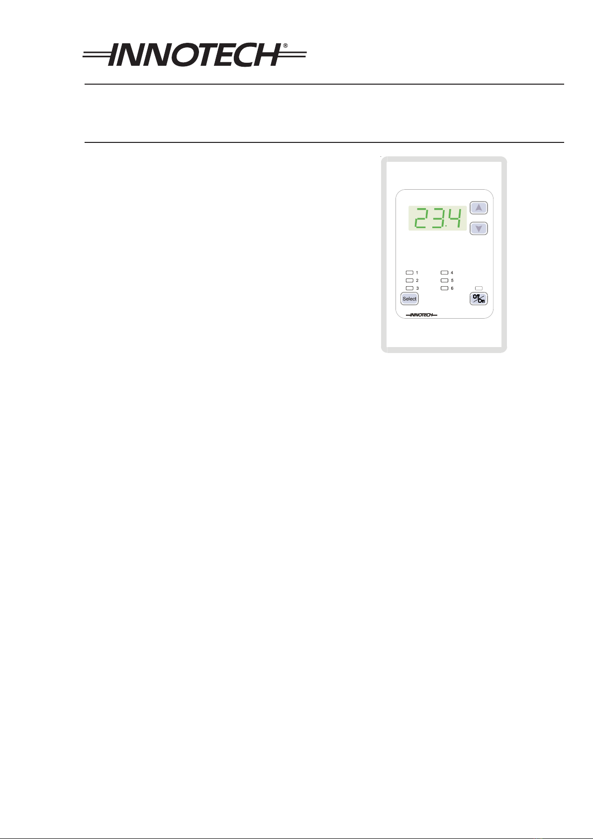
Overview
The Innotech GENII MZSAH REM Multi-Zone Station Module is an
expansion device for the GENESIS range of Digital Controllers.
The module is powered by 24VAC and provides a limited User
Interface to the GENESIS Controller. There are no physical
connections between field equipment and the GENII MZSAH
REM, all input/output values are edited and viewed on the wall
unit.
The GENII MZSAH REM may be located remotely from the
GENESIS Controller providing a distributed User Interface for the
system.
The GENII MZSAH REM is configured via the wallplate and
programmed via the GEN2Config Soware.
The GENII MZSAH REM communicates with the Genesis
Controller via the REM Comms port. The remote link uses RS-485
at a baud rate of 38400. For pre-version 5 controllers, a Gen II
RMI Remote Module Interface is required.
Please refer to DS 15.01 for further information.
Features
• One three decimal place numerical value input
• One three decimal place numerical output
• One momentary digital input
• One LED digital display output
• One ‘current zone’ input
• Housed in a switchplate that mounts in standard electrical
wall plates
• RS485 interconnection between REM Modules
• 24VAC operation
• Wiring Diagrams for modules generated by GEN2Config
Soware
• Adjustable user input range
• Configurable power on settings
• LED indication of network traic on rear to ease debugging &
setup
Approvals
The GENII MZSAH REM conforms to:
• EN 55011 Class B Group 1 & AS/NZS 2064:1997 for RCM
Labelling
• FCC Title 47 CFR, Part 15 Class A for FCC Marking
• UL listed to UL916, File Number E242628

© MASS ELECTRONICS Pty Ltd 2006
Page 2
DS 15.12 - GENII MZS REM - Multi-zone Station Aer Hours Remote Expansion Module
August 2013
Specifications
Power Supply
• Voltage: 24VAC ±10% @ 50/60Hz
• Power Consumption: 3VA max
The operating voltage must meet the requirements of Safety Extra Low
Voltage (SELV) to EN60730. The transformer used must be a Class 2 safety
transformer that has the energy and voltage limiting characteristics as
described in the National Electrical Code, ANSI/NFPA70. It must also be sized
and fused in compliance with local safety regulations.
Inputs
• Push buttons for adjusting control values
• Push button for toggling of “digital function”
• Push button for zone selection
Outputs
• No physical outputs
• Display of Temperature and Setpoint
Terminal Identification
1 24VAC Supply
2 0VAC Supply
3 Earth
TERMINAL 3 is for the protection of the Comms circuitry and
must be connected to a good electrical bonded Earth.
COMMS Connection
SHLD 1 Shield from incoming Comms Cable.
+ RS 485 (+) signal.
- RS 485 (-) signal.
SHLD 2 Shield from outgoing Comms Cable.
Temperature Ratings
• Storage 0 to 50°C non-condensing
• Operating 0 to 40°C non-condensing
Enclosure
The GENII MZSAH REM Modules are housed in switchplate that
mounts in standard electrical wall plates.
Colour: White
Mounting: Wall mounted
Installation
• The Cable run between the GENII MZSAH REM and the GENII RMI
should not exceed 500 mtrs. The Comms wiring requires cable
especially suited for RS485. Other shielded cable is not suitable
and may cause spasmodic Comms failures.
• Strictly follow the guidelines when installing the Comms wiring as
outlined in the Genesis II Installation Manual.
• Mount the GENII MZSAH REM in a dry and clean location free of
excess vibration.
The REM address must be set by programming Parameter 0.
Please refer to the Program Functions section of this data
sheet for more specific information regarding this.
Wiring
• The cable used for RS485 Comms must be shielded single
twisted pair, 120 ohms character impedence, 36 to 45pF per
metre capacitance between conductors.
• The Comms cable must be organised as a bus topology. That is,
starting at one end, devices are connected to it until the other
end of the cable is reached. No “stubs” are allowed. To connect
a device to the cable, as cut is made in the cable at the point
where the device is to be situated along it. Then, the two new
ends of the cable are wired into the device. The shields from the
two new ends are then terminated into the terminals marked
SHLD1 and SHLD2.
• Refer to the Genesis Network Installation Instructions for more
information.
FCC Class A Notice
This device complies with Part 15 of the FCC Rules. Operation is
subject to the following two conditions:
• This device may not cause harmful interference.
• This device must accept any interference received, including
interference that may cause undesired operation.
Note – This equipment has been tested and found to comply with the limits for a Class A
digital device, pursuant to Part 15 of the FCC Rules. These limits are designed to provide
reasonable protection against harmful interference when the equipment is operated
in a commercial environment. This equipment generates, uses and can radiate radio
frequency energy and, if not installed and used in accordance with the instruction
manual, may cause harmful interference to radio communications. Operation of this
equipment in a residential area is likely to cause harmful interference in which case the
user will be required to correct the interference at his own expense. Modifications to this
device, may void the authority granted to the user by the FCC to operate this equipment.
© MASS ELECTRONICS Pty Ltd 2006
Page 3
DS 15.12 - GENII MZS REM - Multi-zone Station Aer Hours Remote Expansion Module
August 2013
Program Functions On The GENII MZSAH REM
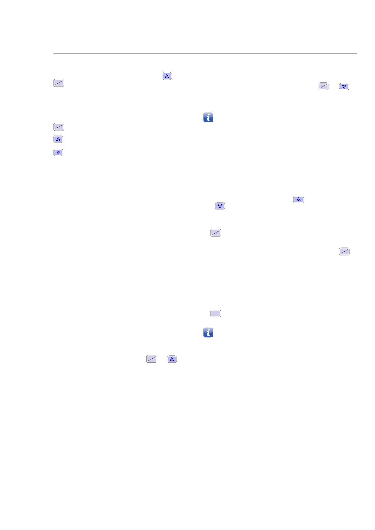
Start Programming Mode
To enter Programming Mode depress and hold the and
ON
OFF buttons for 5 seconds. The display will become blank
indicating that you are in the Programming Mode. Release both
keys and the display will show parameter 0.
Whilst in the programming mode the following buttons are
active:
ON
OFF Change to the next parameter.
Increase the current parameters value.
Decrease the current parameters value.
Parameter 0: Rem Address
This parameter is only available for Zone 0.
The display will show the current REM Address of the device.
• The range of address is 0 to 15
• The default address is 0
Parameter 1: Maximum Input Value
The display will show the Maximum Input Value to which the
module’s input can be set.
• The range of Maximum Input Value is 0.0 to 99.9
• The factory default setting is 30.0
Parameter 2: Minimum Input Value
The display will show the Minimum Input Value to which the
module’s input can be set.
• The range of Minimum Input Value is 0.0 to 99.9
• The factory default setting is 15
Parameter 3: Decimal Position
The display will show the position of the decimal point.
• The range of Maximum Input Value is 0.0 to 2.0
• The factory default setting is 1.0
Parameter 4: Zone Enable
The display will show whether the zone is enabled.
• 1 - Zone Enabled
• 0 - Zone Disabled
Exit Programming Mode
To exit the Programming Mode depress the ON
OFF and
buttons and the new setting will be saved.
Start Up Default Settings
The GENII MZSAH REM Module can be set to start in any mode of
operation.
1. To set the start up default, adjust the GENII MZSAH REM Module to
the desired settings and then press and hold the ON
OFF and
buttons for 5 seconds.
2. The display will become blank indicating that the new settings
have been saved.
Each Zone can have individual settings.
OPERATING FUNCTIONS ON THE GENII MZSAH REM
Numerical Output
The GENII MZSAH REM Module will display a 3 digit, single decimal place
analogue output value during normal operation.
Numerical Input
The GENII MZSAH REM Module will provide a 3 digit, single decimal
place analogue input value to the GENESIS Controller during normal
operation.
This value can be modified by pressing the button to increase
or the button to decrease the value. The value will increase or
decrease by the least significant digit as set by Parameter 3.
Momentary Digital Input Value
The
ON
OFF button on the GENII MZSAH REM Module provides a digital
input value to the GENESIS II Digital Controller during normal operation.
This operates as a standard momentary switch, i.e. Pressing the
ON
OFF
button produces a momentary digital input to the Genesis II Digital
Controller for the selected zone.
Digital Run Led
The GENII MZSAH REM displays a digital state via the On/O led during
normal operation.
Select Button And Zone Led
The Select button is used to increment the current zone to the next ena-
bled zone. The zone led indicates which zone is current.
Each zone has its own set of parameters.

© MASS ELECTRONICS Pty Ltd 2006
Page 4
DS 15.12 - GENII MZS REM - Multi-zone Station Aer Hours Remote Expansion Module
August 2013
Wiring Diagram
YOUR DISTRIBUTOR
Australian Owned, Designed & Manufactured
by Mass Electronics Brisbane
Phone: +61 7 3421 9100 Fax: +61 7 3421 9101
Email:
[email protected] www.innotech.com.au
The INNOTECH device and the word INNOTECH are registered or unregistered trademarks of Mass Electronics Pty Ltd in Australia, USA and other countries
Other Innotech Control Unit manuals


Popular Control Unit manuals by other brands

KIESELMANN
KIESELMANN 402 Series Operating instruction

Viessmann
Viessmann EM-EA1 extension Installation and service instructions for contractors

Rockwell Automation
Rockwell Automation Allen-Bradley ControlLogix 1756-HSC user manual

Hydac
Hydac FMM-O-M Series Installation and maintenance instructions

Dynamic Controls
Dynamic Controls DX-ACC2 installation manual

Compac
Compac C4000 Futra manual


