manuals.online logo
Brands
  1. Home
  2. •
  3. Brands
  4. •
  5. M-system
  6. •
  7. Control Unit
  8. •
  9. M-system R6S-RS2 User manual

M-system R6S-RS2 User manual

EM-7781-BL Rev.4 P. 1 / 4
MG CO., LTD. www.mgco.jp
5-2-55 Minamitsumori, Nishinari-ku, Osaka 557-0063 JAPAN
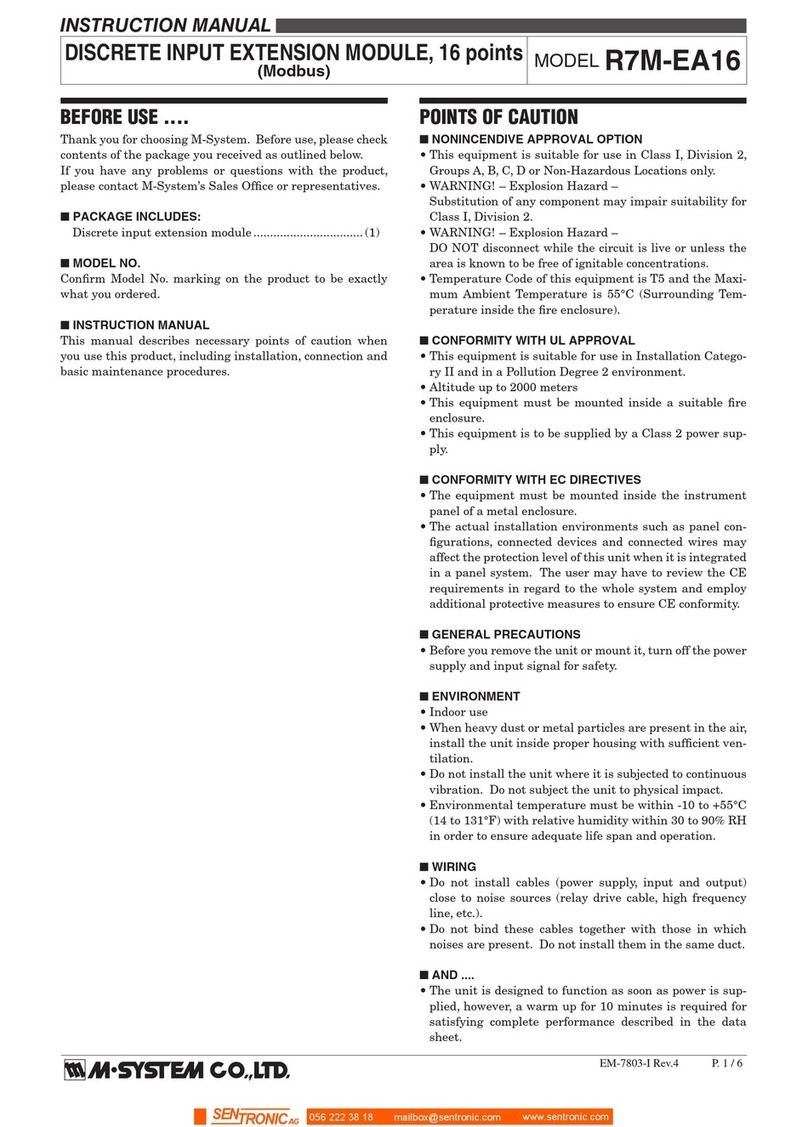
INSTRUCTION MANUAL
RTD INPUT MODULE, 2 points
(Tension clamp) MODEL R6S-RS2
BEFORE USE ....
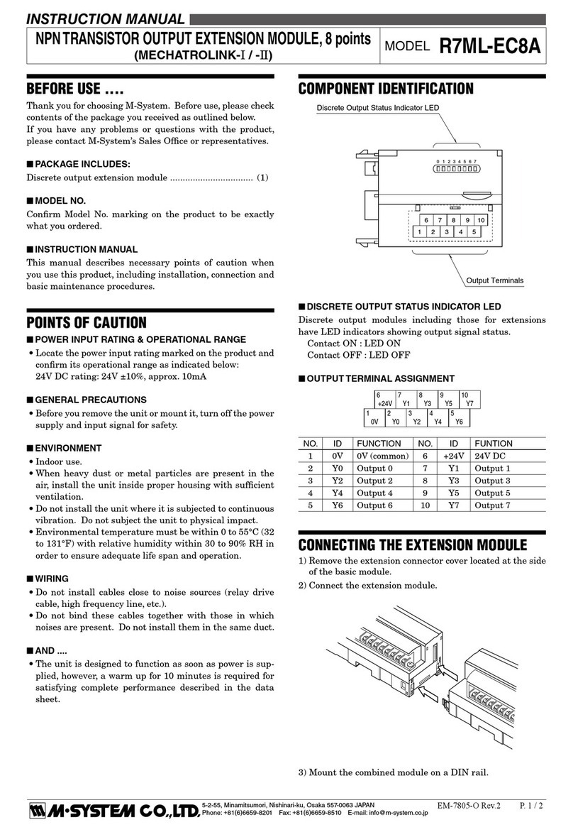
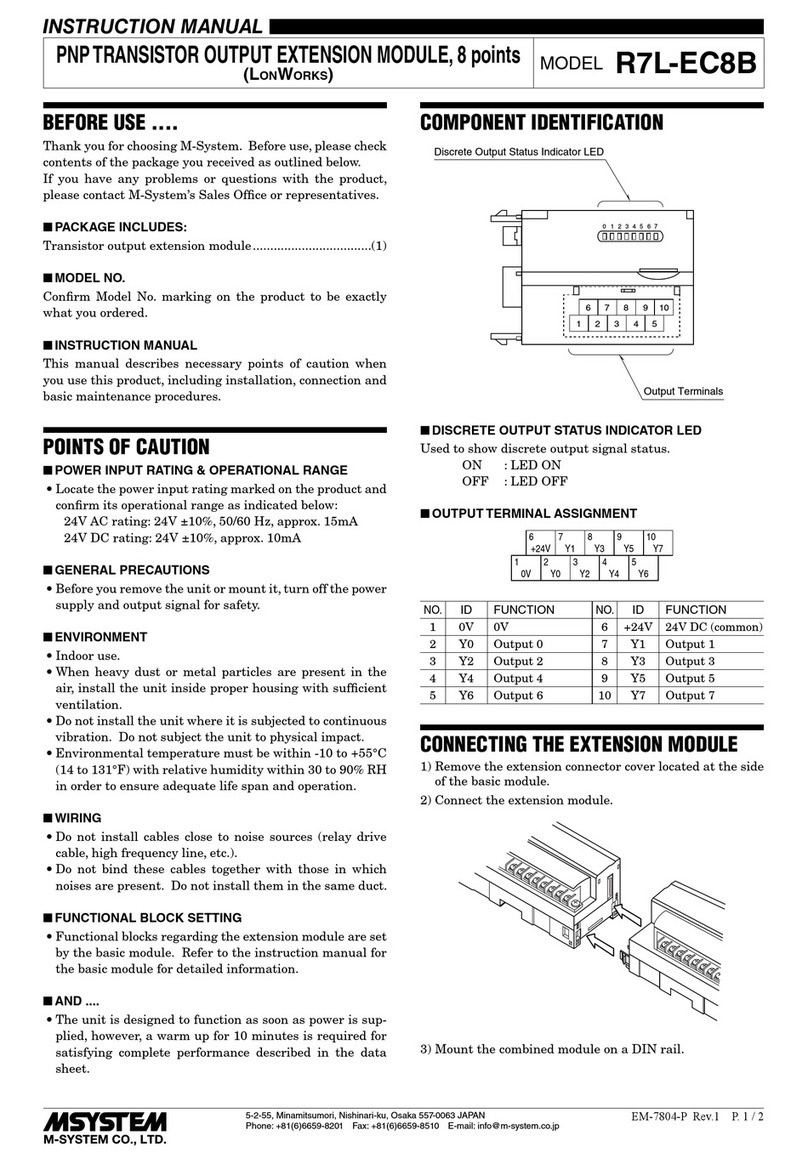
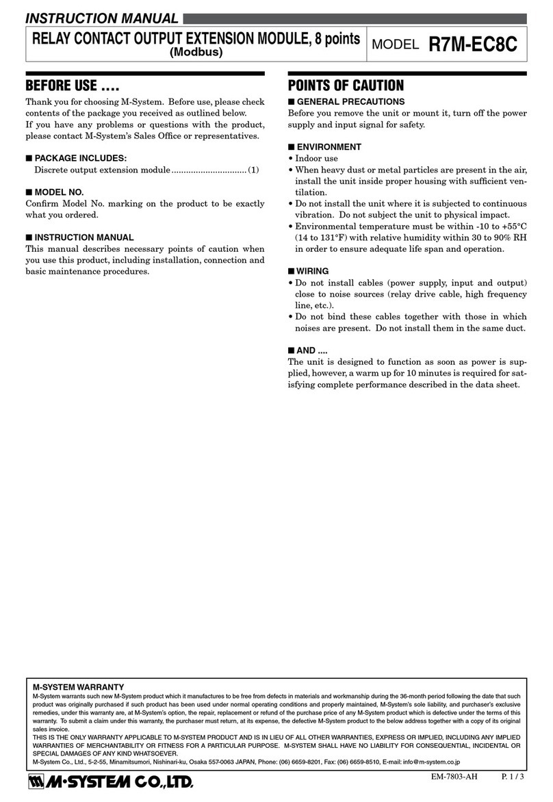
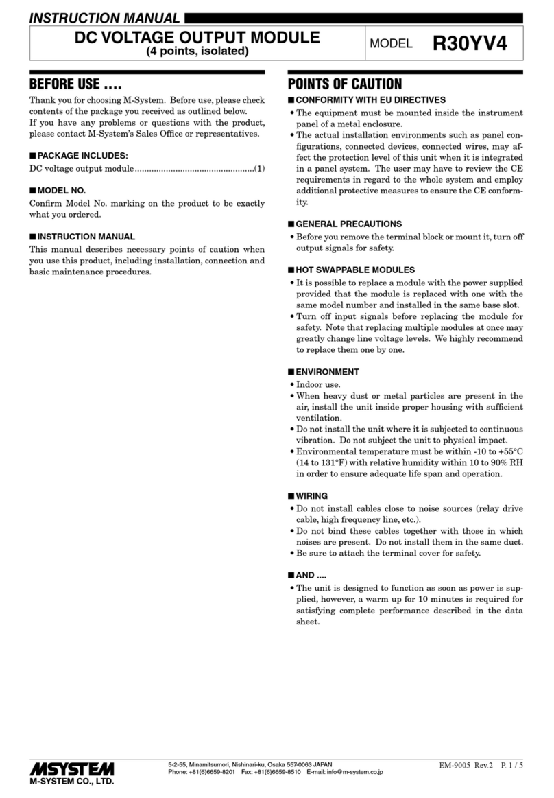
Thank you for choosing us. Before use, please check con-
tents of the package you received as outlined below.
If you have any problems or questions with the product,
please contact our sales office or representatives.
■PACKAGE INCLUDES:
RTD input module...............................................................(1)
■MODEL NO.
Confirm Model No. marking on the product to be exactly
what you ordered.
■INSTRUCTION MANUAL
This manual describes necessary points of caution when
you use this product, including installation, connection and
basic maintenance procedures.
The unit is programmable using the PC Configurator Soft-
ware. For detailed information on the PC configuration, re-
fer to the R6CON users manual. The R6CON PC Configu-
rator Software is downloadable at our web site.
POINTS OF CAUTION
■CONFORMITY WITH EU DIRECTIVES
• The equipment must be mounted inside a panel.
• Insert a noise filter for the input and communication line
connected to the unit. NEC TOKIN Model ESD-SR-250
or equivalent is recommended.
• The actual installation environments such as panel con-
figurations, connected devices, connected wires, may af-
fect the protection level of this unit when it is integrated
in a panel system. The user may have to review the CE
requirements in regard to the whole system and employ
additional protective measures to ensure the CE conform-
ity.
• Install lightning surge protectors for those wires connect-
ed to remote locations.
■HOT INSERTION/REMOVAL OF MODULES
• Removing or replacing modules does not affect other mod-
ules on the same backplane. It is possible to replace them
without removing the power supply. However, replacing
multiple modules at once may greatly change line voltage
levels. We recommend that you replace them one by one.
■GENERAL PRECAUTIONS
• Do NOT set the switches while the power is supplied.
The switches are used only for maintenance without the
power.
■ENVIRONMENT
• Indoor use.
• When heavy dust or metal particles are present in the
air, install the unit inside proper housing with sufficient
ventilation.
• Do not install the unit where it is subjected to continuous
vibration. Do not subject the unit to physical impact.
• Environmental temperature must be within -10 to +55°C
(14 to 131°F) with relative humidity within 30 to 90% RH
in order to ensure adequate life span and operation.
■WIRING
• Do not install cables close to noise sources (relay drive
cable, high frequency line, etc.).
• Do not bind these cables together with those in which
noises are present. Do not install them in the same duct.
■AND ....
• The unit is designed to function as soon as power is sup-
plied, however, a warm up for 10 minutes is required for
satisfying complete performance described in the data
sheet.
COMPONENT IDENTIFICATION
Specifications
Body
Front Cover
Mounting Adaptor
INSTALLATION
Mount the unit on the base (model: R6S-BS).
R6S-RS2
EM-7781-BL Rev.4 P. 2 / 4
MG CO., LTD. www.mgco.jp
5-2-55 Minamitsumori, Nishinari-ku, Osaka 557-0063 JAPAN
EXTERNAL VIEWS
8
6
7
3
4
5
2
1
0
F
E
D
C
B
A
9
• Front View (cover opened) • Side View
5678
1234
1
SW3
SW2
SW1
2345678
OFF
ON
0
16
SW3
SW2
SW1
Module Address
Setting
Operating Mode
Setting
Status LED
Power LED
■INDICATOR LED
ID COLOR FUNCTION
Power OFF Power supply is off
Green ON Power supply is on.
Status OFF Standing by (at the startup)
or communication error
Green ON Normal communication
Green blink Configuration mode
Red ON DIP switch error
Red blink
2 sec. interval
Parameter error
Red blink
0.5 sec. interval
Burnout
■MODULE ADDRESS
Module address is selectable between 0 and 31. Choose 0 or
16 with SW1 for offsetting the address selected with SW2 (0
to F, hexadecimal).
The module’s slot position on the base and the module ad-
dress are not necessarily correlated.
ADDRESS SW1 SW2 ADDRESS SW1 SW2
0 0 0 16 16 0
1 0 1 17 16 1
2 0 2 18 16 2
3 0 3 19 16 3
4 0 4 20 16 4
5 0 5 21 16 5
6 0 6 22 16 6
7 0 7 23 16 7
8 0 8 24 16 8
9 0 9 25 16 9
10 0 A 26 16 A
11 0 B 27 16 B
12 0 C 28 16 C
13 0 D 29 16 D
14 0 E 30 16 E
15 0 F 31 16 F
■OPERATING MODE
(*) Factory setting
• RTD Type
RTD
INPUT 1 INPUT 2
SW3 SW3
123456
Pt 100 (JIS ’97, IEC) (*)
Pt 100 (JIS ’89) ■ ■
JPt 100 (JIS ’89) ■ ■
Pt 50Ω (JIS ’81) ■ ■ ■ ■
Ni 100 ■ ■
Cu 10 @25°C ■ ■ ■ ■
Cu 50 ■ ■ ■ ■
■= ON, Blank = OFF
• Burnout
BURNOUT SW3-7
Upscale (*)
Downscale ■
■= ON, Blank = OFF
• Conguration Mode
CONFIGURATION MODE SW3-8
DIP SW (*)
PC ■
■= ON, Blank = OFF
R6S-RS2
EM-7781-BL Rev.4 P. 3 / 4
MG CO., LTD. www.mgco.jp
5-2-55 Minamitsumori, Nishinari-ku, Osaka 557-0063 JAPAN
TERMINAL CONNECTIONS
Connect the unit as in the diagram below or refer to the connection diagram on the side of the unit.
■EXTERNAL DIMENSIONS unit: mm (inch)
94 (3.70)
5.9 (.23)
*Use a minus screwdriver: tip width 3.8 mm max., tip thickness 0.5 to 0.6 mm
102 (4.02)
WIRE INSERTION ANGLE
: approx.35°
TEST PROBE
max. 2 (.08) dia.
SCREWDRIVER
*
INSERTION ANGLE
: approx. 35°
5678
1234
■CONNECTION DIAGRAM
BUS CONNECTOR
3
1
2
7
5
6
INTERNAL
POWER
INTERNAL
BUS
INPUT 1
INPUT 2
A
B
B
RTD
A
B
B
RTD
• Unused Input Channels
Close across the unused input terminals with a resistor as
shown below and set the DIP switch for Pt 100 input.
1
2
INPUT 1
5
6
INPUT 2
100Ω
3 7
If a resistor is not connected to unused input terminals, sta-
tus indicator LED blinks in red (0.5 sec. cycle), and a burn-
out flag is set in the PLC or the host device.
■WIRING INSTRUCTIONS
• Applicable wire size
Solid: 0.2 to 2.5 mm2(0.55 to 1.75 dia.)
Stranded: 0.2 to 2.5 mm2(Tinning wire ends may cause
contact failure and therefore is not recom-
mended.)
Ferruled: 0.2 to 1.5 mm2(0.55 to 1.35 dia.)
• Expose wire conductors by 8 mm (0.31”).
• How to Connect Wires
Screwdriver
Wire
R6S-RS2
EM-7781-BL Rev.4 P. 4 / 4
MG CO., LTD. www.mgco.jp
5-2-55 Minamitsumori, Nishinari-ku, Osaka 557-0063 JAPAN
1) Insert a minus screwdriver into the wire entry opening,
between the clamp and the housing, until its tip hits the
bottom where it is firmly held.
Tension Clamp
Screwdriver
2) Insert a wire. Push the screwdriver toward the direction
indicated with the arrow in the figure below to widen the
opening if necessary.
Wire Entry
Wire
3) Confirm that the wire tip hits the bottom and pull out the
screwdriver in holding it in position.
Confirm that the wire’s insulation tube is not caught in
the clamp.
PC CONFIGURATOR
With configurator software, settings shown below are avail-
able.
Refer to the software manual of R6CON for detailed opera-
tion.
■CHANNEL INDIVIDUAL SETTING
PARAMETER AVAILABLE RANGE
DEFAULT SETTING
Sensor type Pt 100 (JIS ’97, IEC)
Pt 100 (JIS ’89)
JPt 100 (JIS ’89)
Pt 50Ω (JIS ’81)
Ni 100
Cu 10 @ 25°C
Cu 50
Pt 100 (JIS
’97, IEC)
Lower range value
Depends on sensor type
0.00 (degC)
Upper range value
Depends on sensor type
0.00 (degC)
Fine zero adjustment
-320.00 to +320.00 (%) 0.00 (%)
Fine gain adjustment
-3.2000 to +3.2000 1.0000
Scaled range Zero -32000 to +32000 0
Scaled range Span -32000 to +32000 10000
Burnout Upscale, Downscale Upscale
■CHANNEL BATCH SETTING
PARAMETER AVAILABLE RANGE
DEFAULT SETTING
Loss of internal
bus communication
detection time
0.0 – 99.9 (sec.) 1.0 (sec.)
Conversion rate 250, 500 (msec.) 500 (msec.)
Temperature unit degC, degF, K degC
Limit -15 to +115%
Scaled range Zero /
Span
-15 to +115%

Other M-system Control Unit manuals

M-system R7C-EC8B/UL User manual

M-system

M-system R7C-EC8B/UL User manual

M-system R7M-DA16 User manual

M-system

M-system R7M-DA16 User manual

M-system R3-PA4 User manual

M-system

M-system R3-PA4 User manual

M-system R3-NC2 User manual

M-system

M-system R3-NC2 User manual

M-system M6NPS2 User manual

M-system

M-system M6NPS2 User manual

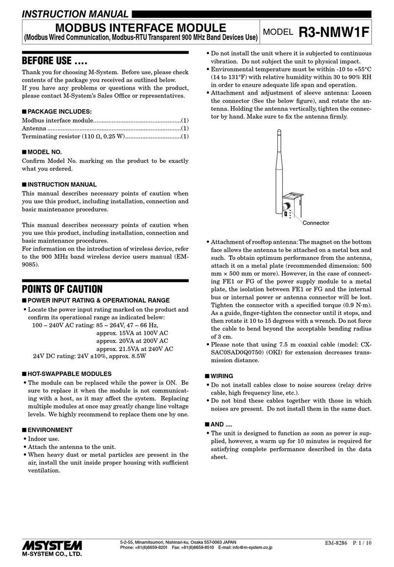
M-system R3-NMW1F User manual

M-system

M-system R3-NMW1F User manual

M-system R7G4HH-A-YVF4 User manual

M-system

M-system R7G4HH-A-YVF4 User manual

M-system R7M-CT4E User manual

M-system

M-system R7M-CT4E User manual

M-system LONWORKS R3-NL2 User manual

M-system

M-system LONWORKS R3-NL2 User manual

M-system 61A User manual

M-system

M-system 61A User manual

M-system R6N-RS2 User manual

M-system

M-system R6N-RS2 User manual

M-system R7C-DC16A User manual

M-system

M-system R7C-DC16A User manual

M-system M6NPS1 User manual

M-system

M-system M6NPS1 User manual

M-system R7D-MS4 User manual

M-system

M-system R7D-MS4 User manual

M-system R7F4HML3-D-DAC32A User manual

M-system

M-system R7F4HML3-D-DAC32A User manual

M-system EtherCAT R7I4DECT-1-PA8A User manual

M-system

M-system EtherCAT R7I4DECT-1-PA8A User manual

M-system R3-PD16B User manual

M-system

M-system R3-PD16B User manual

M-system R3-NP1 User manual

M-system

M-system R3-NP1 User manual

M-system R7C-EC8B User manual

M-system

M-system R7C-EC8B User manual

M-system R3-PT4 User manual

M-system

M-system R3-PT4 User manual

M-system R7L-EC8A User manual

M-system

M-system R7L-EC8A User manual
M-system R7ML-DC16A User manual

M-system

M-system R7ML-DC16A User manual

M-system Devicenet R7F4HD-DAC32D User manual

M-system

M-system Devicenet R7F4HD-DAC32D User manual

M-system R8-DC4C User manual

M-system

M-system R8-DC4C User manual

Popular Control Unit manuals by other brands

National Instruments PXIe-8245 Getting started guide

National Instruments

National Instruments PXIe-8245 Getting started guide

Tuxhorn tubra-eTherm manual

Tuxhorn

Tuxhorn tubra-eTherm manual

Texas Instruments LM5123EVM-BST user guide

Texas Instruments

Texas Instruments LM5123EVM-BST user guide

Gemu 650 manual

Gemu

Gemu 650 manual

Pilz PSSuniversal PSSu H F PN operating manual

Pilz

Pilz PSSuniversal PSSu H F PN operating manual

Seraphim SRP-XXX-6PA-BB installation guide

Seraphim

Seraphim SRP-XXX-6PA-BB installation guide

Pentair Aurora CBV-S Installation and operation manual

Pentair

Pentair Aurora CBV-S Installation and operation manual

Bartec APEX px operating instructions

Bartec

Bartec APEX px operating instructions

Siemens SIRIUS manual

Siemens

Siemens SIRIUS manual

oventrop Regufloor H Installation and operating instructions for the specialised installer

oventrop

oventrop Regufloor H Installation and operating instructions for the specialised installer

CTC Union ETU01 user manual

CTC Union

CTC Union ETU01 user manual

Vag DUOJET Series Operation and maintenance instructions

Vag

Vag DUOJET Series Operation and maintenance instructions

Lutron Electronics QSN-2DALUNV-S install guide

Lutron Electronics

Lutron Electronics QSN-2DALUNV-S install guide

Burkert 2933 operating instructions

Burkert

Burkert 2933 operating instructions

Easy ELC12 Series user manual

Easy

Easy ELC12 Series user manual

Eaton Cutler-Hammer IQMSSPM instructions

Eaton

Eaton Cutler-Hammer IQMSSPM instructions

Warren rupp Sandpiper HD20F Service & operating manual

Warren rupp

Warren rupp Sandpiper HD20F Service & operating manual

Radionics D8128D installation instructions

Radionics

Radionics D8128D installation instructions

manuals.online logo
manuals.online logoBrands
  • About & Mission
  • Contact us
  • Privacy Policy
  • Terms and Conditions

Copyright 2025 Manuals.Online. All Rights Reserved.