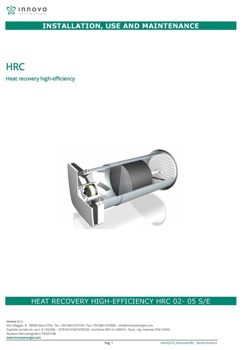
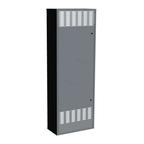
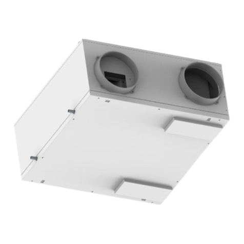
Innova HRC 08 Service manual

Page1
INSTALLATION, USE AND MAINTENANCE MANUAL
DECENTRALIZED HIGH EFFICIENCY HEAT RECOVERY UNIT

Page2
INDEX
1GENERALITY ..................................................................................................................................................................4
1.1.1 INTRODUCTION.................................................................................................................................................4
1.1.2 BASIC SAFETY RULES .....................................................................................................................................4
1.1.3 SYMBOLOGY .....................................................................................................................................................5
1.1.4 WARNINGS ........................................................................................................................................................5
1.1.5 COMPLIANCE ....................................................................................................................................................6
1.1.6 RANGE ...............................................................................................................................................................6
1.1.7 IDENTIFICATION................................................................................................................................................7
1.1.8 CONSTRUCTION FEATURES...........................................................................................................................7
1.1.9 OPERATION DESCRIPTION .............................................................................................................................8
1.1.10 DELIVERY STATE ..........................................................................................................................................8
1.1.11 START-UP REQUIREMENTS ........................................................................................................................8
1.1.12 DISASSEMBLY AND DISPOSAL ...................................................................................................................8
2INSTALLATION ...............................................................................................................................................................9
2.1.1 INSTALLATION CONDITIONS...........................................................................................................................9
2.1.2 UNIT PLACEMENT...........................................................................................................................................10
2.1.3 CONDENSATE DRAIN CONNECTION (enthalpy version not present X) .......................................................16
3ELECTRICAL CONNECTIONS.....................................................................................................................................17
3.1.1 GENERALITY ...................................................................................................................................................17
3.1.2 UNIT WIRING DIAGRAMS ...............................................................................................................................19
3.1.3 ELECTRICAL CONNECTIONS VERSION -I- ...................................................................................................20
4COMMISSIONING AND METHOD OF USE .................................................................................................................21
4.1.1 GENERALITY ...................................................................................................................................................21
4.1.2 PANEL DESCRIPTION ON THE MACHINE ....................................................................................................21
4.1.3 PSSWITCH SETTINGS ....................................................................................................................................22

Page3
4.1.4 VERSION OPERATION -I- ...............................................................................................................................23
5MAINTENANCE.............................................................................................................................................................26
5.1.1 CLEANING OR REPLACING FILTERS............................................................................................................26
5.1.2 CLEANING THE HEAT EXCHANGER .............................................................................................................27
5.1.3 GENERAL CLEANING OF THE UNIT..............................................................................................................28
6ALARMS ........................................................................................................................................................................29
6.1.1 GENERALITY ...................................................................................................................................................29
6.1.2 PROBLEMS WITHOUT ERROR INDICATION ON THE DISPLAY .................................................................29
6.1.3 ALARM SIGNALING .........................................................................................................................................30
6.1.4 TABLE OF ALARMS INDICATED BY THE DISPLAY - VERSIONS I -............................................................30
7NOTES AND MAINTENANCE INFORMATION ............................................................................................................31
NOTE .............................................................................................................................................................................31

Page4
1 GENERALITY
1.1.1 INTRODUCTION
This manual was conceived with the aim of making installation and management of your system as simple as possible.
By reading and applying the suggestions in this manual, you will be able to obtain the best performance from the purchased product.
We would like to thank you for the choice you made by purchasing our product.
Read this booklet carefully before carrying out any operation on the unit.
The unit must not be installed or performed on it in any way unless this manual has been carefully read and understood in all its parts. In particular, all
the precautions listed in the manual must be taken.
The documentation supplied with the unit must be handed over to the system manager so that he can keep it carefully (at least 10 years) for any future
assistance, maintenance and repairs.
The installation of the unit must take into account both the purely technical requirements for correct operation and any local legislation
in force and specific provisions.
Make sure that when the unit is delivered, there are no obvious signs of transport damage. In this case, indicate it on the delivery note.
This manual reflects the state of the art at the time the machine was marketed and cannot be considered inadequate because it is subsequently
updated on the basis of new experiences. The Manufacturer reserves the right to update the production and the manuals, without the obligation to
update the previous ones, except in exceptional cases.
Contact the Manufacturer's Sales Department to receive further information or updates to the technical documentation and for any improvement
proposal to this manual. All reports received will be rigorously screened.
1.1.2 BASIC SAFETY RULES
We remind you that the use of products that use electricity and water implies the observance of some basic safety rules:
•Use of the appliance by disabled and unassisted persons is prohibited
•It is forbidden to touch the appliance with bare feet and with wet or damp parts of the body
•Any cleaning operation is prohibited before having disconnected the appliance from the mains power supply by setting the main system switch
to off
•It is forbidden to modify the safety or adjustment devices without the authorization and indications of the appliance manufacturer
•It is forbidden to pull, disconnect or twist the electric cables coming out of the appliance, even if this is disconnected from the mains power
supply.
•It is forbidden to introduce objects and substances through the air intake and delivery grilles.
•It is forbidden to open the access doors to the internal parts of the appliance without having first turned the main switch of the system to off.
•It is forbidden to disperse and leave the packaging material within the reach of children as it can be a potential source of danger.
•Respect the safety distances between the machine and other equipment or structures to guarantee sufficient access space to the unit for
maintenance and assistance operations as indicated in this booklet.
•The power supply of the unit must take place with electric cables having a section suitable for the power of the unit. The voltage and
frequency values must correspond to those indicated for the respective machines; all machines must be earthed as per current legislation in
the various countries.

Page5
1.1.3 SYMBOLOGY
The symbols shown in the following file allow you to quickly provide the information necessary for correct use of the unit.
Safety related symbols
ATTENTION
Authorized personnel only Warns that the operations indicated are important for the safe operation of the machines
DANGER
Risk of electric shock Warns that failure to observe the instructions involves a risk of electric shock.
DANGER Warns that failure to observe the instructions involves a risk of harm to exposed persons.
WARNING It warns that failure to observe the instructions involves a risk of damage to the unit or the system.
DANGER Warns that there is the presence of moving parts and involves a risk of harm to exposed persons
1.1.4 WARNINGS
The installation of the unit must be carried out by qualified and authorized personnel according to the regulations in force in the various
countries.
If the installation is not performed it could become a dangerous situation
Avoid installing the unit in very humid rooms or with the presence of large heat sources.
On the electrical side, to prevent any risk of electrocution, it is essential to disconnect the main switch before carrying out any operations
electrical connections and any maintenance operation.
In the event of water leaks inside the unit, position the main switch of the system to "Off", close the taps of the
water and contact the technical service
It is recommended to use a dedicated power circuit; Never use a power supply in common with other appliances.
It is recommended to install an earth leakage breaker; failure to install this device may result in shock
electric.

Page6
For the connection, use a cable long enough to cover the entire distance, without any connection; do not use
extension cords and do not apply other loads on the power supply but use a dedicated power circuit.
After connecting the electric cables, make sure that the cables are arranged so as not to exert excessive forces on the covers or on the
electrical panels; any incomplete connection of the covers may cause overheating of the terminals.
Make sure that the earth connection is made; do not earth the appliance on distribution pipes.
High intensity surge currents could damage the unit
Installations carried out outside the warnings of this manual or use outside the operating limits will invalidate
the guarantee instantly.
Make sure that the first start-up is carried out by personnel authorized by the company (see first start-up request form)
1.1.5 COMPLIANCE
The CE marking (present on each machine) certifies compliance with the following EU standards:
•Low Voltage Directive 2014/35/EC
•Electromagnetic Compatibility Directive 2014/30/EC
•Ecodesign 2009/125/EC
•RoHS2 2011/65/EU
•WEEE 2012/19/EC
1.1.6 RANGE
-1-
-2-
-3-
-4-
HRC 08
08
V
X
I
1) Defines the maximum range
Size: 08 up to 80 m³/h
2) Type of installation
V: Vertical view
3) Type of exchanger
V: sensitive
X: enthalpic
4) Type of control
I: electronics I

Page7
1.1.7 IDENTIFICATION
- The unit can be identified by the plate placed on the lower front panel of the same.
- On the packaging there will be an additional identification plate with the unit model and shipping references.
- The label on the packaging has no value for the traceability of the product in the years following the sale.
The removal, deterioration and illegibility of the plate placed on the unit, entails major problems in identifying the machine, in finding spare parts and
therefore in any future maintenance.
1.1.8 CONSTRUCTION FEATURES
HRC 08 is a very high efficiency dual flow decentralized ventilation unit;
The unit is particularly suitable for residential units with the possibility of installing the number of units necessary to cover the house's air exchange
requirement; Each unit covers approximately 50-60 m2 of surface.
CHASSIS:
Self-supporting sheet metal frame
Galvanized sheet panels, with internal insulation in high density polyethylene;
External painting of the aesthetics with RAL9003 finish;
HEAT EXCHANGER:
High efficiency counter-current cross-flow polypropylene heat exchanger.
Low freezing temperatures
Very high exchange efficiency.
FANS:
Brushless fans with electronic motor.
Very high efficiency and low noise levels.
FILTERS:
70/80% ePM1 filters with low pressure drop.
Easily removable both horizontally and vertically.
FREE COOLING:
Free cooling with automatic management through temperature probes
ELECTRICAL CABINET:
Electrical panel complete with 4-speed fan management card, antifreeze, automatic bypass,
temperature probes, post-heating coil management and automatic dirty filter signaling.
Capacitive touch control panel on board the machine, integrated temperature, air quality and
humidity sensors;
Wifi chip for management through remote APP;
EFFICIENCY:
Thanks to the construction features and its components, HRC+ is able to achieve recovery
efficiency greater than 90%.
In the winter and summer seasons there is a considerable energy recovery of the fresh air
introduced into the environment.

Page8
1.1.9 OPERATION DESCRIPTION
The unit is a decentralized ventilation system with heat recovery with the following characteristics and peculiarities:
promotes healthy ventilation in offices, schools, commercial activities allowing the correct air exchange in the rooms and extracting excess humidity and
bad smells;
•allows considerable energy savings for heating thanks to the efficiency of the heat recovery unit greater than 90%;
•the epm1 class filters with low pressure drop guarantee the filtering of the external air, which is essential for allergy sufferers;
•the electronically controlled speed motors guarantee low electricity consumption;
•heat and sound insulation;
•easy access inspection and maintenance by panel with locks;
•frost protection;
•control unit with display;
•predisposition for easy connection to the network and remote control.
1.1.10 DELIVERY STATE
The supply includes:
•recovery unit complete with fans supplied for installation in the pipes
•polypropylene counter-current exchanger pre-inserted inside the unit;
•epm1 class filters pre-inserted inside the unit;
•Telescopic mounting tubes
•Collapsible outdoor grills
•electrical box with connection terminal block;
•wall mounting brackets
•labels/stickers (safety pictograms, identification of air connections, CE marking…) already positioned on the unit.
•2 cable ties
•installation, use and maintenance manual
1.1.11 START-UP REQUIREMENTS
Before starting, make sure there are no foreign bodies inside the unit.
Check the fixings of the closure panels and inspection doors.
Check the power supply and grounding of the unit.
1.1.12 DISASSEMBLY AND DISPOSAL
Do not disassemble or dispose of the product yourself.
The disassembly, demolition, disposal of the product must be carried out by authorized personnel in accordance with local regulations.

Page9
2 INSTALLATION
2.1.1 INSTALLATION CONDITIONS
The unit must be installed according to the national and local standards governing the use of electrical devices and according to the following
indications:
•install the unit inside residential buildings with an ambient temperature between 0°C and 45°C;
•avoid areas near sources of heat, steam, flammable and/or explosive gases and particularly dusty areas;
•install the unit in a place not subject to frost (the condensed water must be discharged not frozen, at a certain angle, using a siphon);
•do not install the unit in areas with a high relative humidity (such as the bathroom or toilet) to avoid condensation on the external surface;
•choose an installation site where there is sufficient space around the unit for the connections of the air ducts and to be able to carry out
maintenance operations;
•the consistency of the ceiling/wall/floor where the unit will be installed must be suitable for the weight of the unit and not cause vibrations.
In the environment chosen for installation there must be:
-external air duct connections;
-230 V single-phase electrical connection
-connection for the condensate drain.

Page10
2.1.2 UNIT PLACEMENT
Unit placement
The unit can be installed against an external wall with the pipes
directly to the outside
The installation takes place directly adjacent to the wall and
directed outward holes;
The assembly sequence includes the installation of the telescopic
tubes, the external grille and the unit;
Unit placement

Page11
Template for wall holes
For the assembly of the unit, a template is supplied to easily make
the holes in the wall of the unit and the fixing points;
•Place the installation template on the wall
•Mark and drill the wall making the two holes for external
air and expulsion of internal air
•Prepare the condensate drain if it is conveyed directly
outside with the air passage holes;
•Ensure sufficient space for carrying out maintenance
activities: the opening of the unit cover must be
guaranteed
•Prepare the fixing holes for the unit
Do not mount the unit with the sides in direct contact with the walls
to avoid possible contact noise;
Wall installation template

Page12
Piping assembly
Sprinkle the hole made with cement mortar or
polyurethane foam.
Insert the telescopic tube inside the hole made and bring
the part of the tube with the larger diameter flush with the
external wall.
Move the part of the pipe with the smaller diameter, bringing
it flush with the internal wall. (fig.3)
Fig.3 Positioning of the telescopic tube
Installation of external grilles
Wait for the cement mortar or polyurethane foam to set.
Insert the grid in-out by compressing the springs on the
larger diameter pipe towards the outward end of the core.
Release and check the fastening of the grille.
Fig.4 Positioning of the external grille

Page13
Fan assembly
Insert the fans in the pipes respecting the indications of
the direction of the fan as shown in the figure shown in the
following image;
-Insert the fan into the pipe with a smaller diameter
avoiding making it slide too much in the pipe;
NB If it is placed in a pipe with a larger diameter, the seal
of the fan gasket could be insufficient;
Insertion of fans
- Follow the diagram on the side and respect the labels
positioned on the fan and on the unit in order to have the
correct installation on the expulsion side and the inlet side;
Correct installation of the fans

Page14
- Wall mounted unit
The unit is supplied with a wall mounting bracket
To fix the unit on the wall:
•Drill and plug the wall bracket using the references
on the assembly template;
•Level the bracket, preferring a minimum inclination
towards the left side condensate drain
•Rest the unit on the bracket, tilting it with the top
towards the wall so that it hooks onto the bracket
and let the unit rotate towards the wall so that there
is adherence between the wall and the rear
insulation;
•Fix the lower central bracket inserted inside the base
to lock the unit to the wall
•Ensure sufficient space for carrying out maintenance
activities: the opening of the cover of the unit (from
below) must be guaranteed.
•Respect the left side distance to have access to the
control display
Do not mount the unit with the sides in direct contact with the
walls to avoid possible contact noise;
Wall mounting

Page15
Fan connectors connection
After installing pipes, fans and units it is necessary to connect
the connectors of the fans to the unit;
To connect the fan connectors;
•Rotate the unit from below, creating a gap between
the wall and the unit;
•Use a temporary support such as a spacer to keep
the unit temporarily off the wall;
•Connect the connectors of the two fans;
Each fan has a 4-pole connector for the power
supply and a 2-pole connector for the signal;
•Pay attention to the positioning of the cables and if
necessary use the two clamps supplied to block
them on the anti-intrusion grille;
•Remove the temporary support and leave the unit
leaning against the wall, paying attention to the
cables that do not interfere with the closing of the
unit;
NB Do not carry out the operation with the unit powered;
Wall mounting

Page16
2.1.3 CONDENSATE DRAIN CONNECTION (NOT PRESENT ENTHALPY VERSION X)
Due to the heat recovery system (the hot exhaust air is cooled by the intake air inside the heat exchanger), the humidity contained in the indoor air
condenses inside the unit.
For the correct functioning of the heat recovery unit, it is therefore necessary to connect a condensate drain to the hydraulic system or to lose it
externally. Furthermore, to allow the correct outflow of the condensate water and to avoid air suction, the condensate drain must always be equipped
with the special siphon by the installer;
For the installation of the condensate drain, comply with the following standards:
•give the drain pipe a slope of at least 2%;
•provide for the possibility of disconnecting the drain hose for any maintenance
•make sure that the discharge end of the hose is at least below the water level of the siphon;
•make sure that the siphon is always full of water and of sufficient height (at least 15-20mm)
On the machine, the drain is placed on the lower part
accessible from the base;
A Dn20 silicone pipe is supplied on the rear side in order to
facilitate exit from the machine and connection to the
condensate drain network;
ATTENTION TO THE HORIZONTAL SECTIONS FOR THE
CONDENSATE DISCHARGE WITH INSTALLATION
DIRECTLY TOWARDS THE OUTSIDE;
IF WATER STAGNANT AND THE OUTDOOR
TEMPERATURES ARE BELOW 0°, THERE IS DANGER OF
FREEZING THE EXHAUST AND THEREFORE POSSIBLE
INTERNAL WATER LEAKS;
Condensate drain

Page17
3 ELECTRICAL CONNECTIONS
3.1.1 GENERALITY
- Before starting any operation to make the electrical connections, make sure that the unit is not electrically powered
- Make the necessary electrical connections by consulting only the electrical diagram attached to this manual.
- Install a suitable cut-off and differential protection device for the exclusive service of the unit.
- It is essential that the unit is connected to an efficient earth connection. The manufacturer refuses all responsibility for non-observance;
- Check that the electrical components chosen for installation (main switch, circuit breakers, cable section and terminals) are suitable for the electrical
power of the installed unit and that they take into account the compressor peak currents as well as the maximum load that can be reached. The relative
data are indicated on the attached wiring diagram and on the unit identification plate
- It is forbidden to enter the unit with electric cables unless specified in this booklet.
- Use cables and electrical conductors with adequate sections and compliant with the regulations in force in the various countries.
- Absolutely avoid running the electrical cables in direct contact with pipes or components inside the unit
- After the first moments of operation, check the tightness of the screws of the power supply terminals
Power line sizing table
Size
70
Maximum absorbed current
TO
0.3
For the electrical connections, a power cable with schuko socket is
supplied;
On the machine the electrical connections are placed on the lower
part and on the rear part;
For the electrical connection of other cables:
•Use the hole adjacent to the electrical cord outlet hole to
route other connections to the unit's electrical panel;
Pay attention that the cables do not come into contact with the
impellers of the fans;

Page18
Electrical connections
The electronic card is located on the front left side of the unit
where any auxiliary connections can be made;
For auxiliary electrical connections
•Use the hole adjacent to the electrical cord outlet hole to
route other connections to the unit's electrical panel;
•Remove the front aesthetic cover as indicated in the
maintenance chapter;
•Remove the 2+2 front panel screws under the grilles
•Use the two cable glands to enter the electrical cables
inside the unit;
•Use electrical cables with double insulation in the
crossing up to the electrical box;
•Enter the cables inside the electrical box and make the
electrical connections;
Auxiliary electrical connections

Page19
3.1.2 UNIT WIRING DIAGRAMS
Version I
LINKS PROVIDED BY THE CUSTOMER
GRID
Speed Booster
Contact closed / function active
CHILLER
Post battery generator control or preheating battery
Clean Contact
REMOTE DISPLAY
Remote control (4 wires)
ON OFF REMOTE (ON DISPLAY)
Remote ON OFF contact present on remote display
Contact closed / unit OFF

Page20
3.1.3 ELECTRICAL CONNECTIONS VERSION -I-
Auxiliary Connections
The card allows the operation of the EC Brushless fan through a remote control described above;
Some auxiliary functions have been implemented in the card such as the connection of the regulators and the management of a battery / post valve;
REMOTE ON OFF LINK
The remote panel has an ON OFF command
with which the unit can be connected via a
clean contact to a device for remotely
switching on / off the unit such as a switch or a
timer
The logic provides:
Contact closed: Unit OFF
Contact open: Unit ON
BOOSTER CONNECTION
The connection of a contact which brings the
ventilation speed to maximum speed is
foreseen;
The connection is made on the GRID
terminals
as indicated on the wiring diagram
Contact closed – booster speed active
Booster connection
Table of contents
Other Innova Heating System manuals

Innova
Innova HRC + User manual

Innova
Innova HRP DOMO SMALL Service manual

Innova
Innova HRC Series Quick start guide

Innova
Innova 2.0 User manual

Innova
Innova HRP DOMO Quick start guide

Innova
Innova HRP DOMO EXT User manual

Innova
Innova HRW DOMO Quick start guide

Innova
Innova EF40 Series Troubleshooting guide

Innova
Innova HRC Instruction manual
Popular Heating System manuals by other brands

LATICRETE
LATICRETE STRATA_HEAT 120V quick start guide

Sun Heat
Sun Heat Thermal Wave TW1500 owner's manual

ProFusion
ProFusion GD8115BP-L owner's manual

Alfalaval
Alfalaval Mini ECO Installation, service and operating instruction

Heat & Glo
Heat & Glo PRIMO Series installation instructions

Delta
Delta K160 user manual