Innova HRP DOMO SMALL Service manual

Innova S.r.l.
Page 1 HRP DOMO SMALL Manual
INSTALLATION, USE AND MAINTENANCE MANUAL
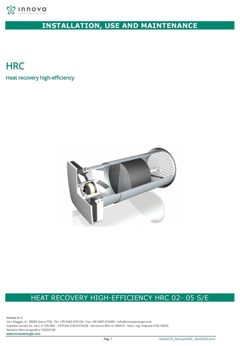
HIGH-EFFICIENCY HEAT RECOVERY UNIT

Innova S.r.l.
Page 2 HRP DOMO SMALL Manual
TABLE OF CONTENTS
1GENERAL INFORMATION .................................................................................................................................................................. 4
1.1 INTRODUCTION ....................................................................................................................................................................... 4
1.2 BASIC SAFETY RULES ....................................................................................................................................................... 4
1.3 SYMBOLS ................................................................................................................................................................................. 4
1.4 WARNINGS .............................................................................................................................................................................. 5
1.5 COMPLIANCE ........................................................................................................................................................................... 6
1.6 RANGE ..................................................................................................................................................................................... 6
1.7 IDENTIFICATION .................................................................................................................................................................. 6
1.8 CONSTRUCTION CHARACTERISTICS......................................................................................................................................... 7
1.9 DESCRIPTION OF OPERATION.................................................................................................................................................. 7
1.10 DELIVERY CONTENTS ............................................................................................................................................................... 7
1.11 START-UP REQUIREMENTS ................................................................................................................................................ 8
1.12 DISMANTLING AND DISPOSAL ........................................................................................................................................... 8
2INSTALLATION ................................................................................................................................................................................... 9
2.1 CONDITIONS OF INSTALLATION .......................................................................................................................................... 9
2.2 POSITIONING THE UNIT ................................................................................................................................................... 10
2.3 CONDENSATE DRAIN CONNECTION ................................................................................................................................ 12
3AIR DUCT CONNECTIONS ................................................................................................................................................................ 12
3.1 AIR DUCT GUIDELINES ....................................................................................................................................................... 13
4ELECTRICAL CONNECTIONS............................................................................................................................................................. 13
4.1 GENERAL INFORMATION ................................................................................................................................................. 14
4.2 UNIT WIRING DIAGRAM ........................................................................................................................................................ 14
4.3 ELECTRICAL CONNECTIONS VERSION -I- ......................................................................................................................... 16
5COMMISSIONING AND OPERATION................................................................................................................................................ 19
5.1 GENERAL INFORMATION ................................................................................................................................................. 20
5.2 OPERATION............................................................................................................................................................................ 20
5.3 SWITCHING THE UNIT ON AND OFF ...................................................................................................................................... 20
5.4 MODIFYING FAN SPEEDS AND BOOSTER FUNCTION............................................................................................................. 21

Innova S.r.l.
Page 3 HRP DOMO SMALL Manual
5.5 NOMINAL SPEED OPERATION ........................................................................................................................................... 21
5.6 CHANGING THE SEASON........................................................................................................................................................ 21
5.7 BUTTON LOCK........................................................................................................................................................................ 21
5.8 PANEL BRIGHTNESS ADJUSTMENT ........................................................................................................................................ 22
6MAINTENANCE................................................................................................................................................................................ 22
6.1 CLEANING AND FILTER REPLACEMENT.................................................................................................................................. 22
6.2 CLEANING THE HEAT EXCHANGER ........................................................................................................................................ 22
6.3 GENERAL CLEANING OF THE UNIT......................................................................................................................................... 23
7ALARMS........................................................................................................................................................................................... 23
7.1 GENERAL INFORMATION ....................................................................................................................................................... 23
7.2 TROUBLESHOOTING WITH NO DISPLAY ERROR .................................................................................................................... 24
7.3 TABLE OF ALARMS INDICATED ON DISPLAY - VERSIONS I - ................................................................................................... 24
8NOTES AND MAINTENANCE INFORMATION................................................................................................................................... 24

Innova S.r.l.
Page 4 HRP DOMO SMALL Manual
1GENERAL INFORMATION
1.1 INTRODUCTION
This manual has been drafted with the aim of making the installation and management of your system as simple as possible.
By reading and taking note of the suggestions in this manual, you will obtain the best performance of the purchased product.
We would like to thank you for choosing to purchase our product.
Please read this manual carefully before carrying out any procedures on the unit.
The unit should not be installed or any work carried out on it until the manual has been read and understood in its entirety. In
particular, all precautions outlined in the manual should be undertaken.
The documentation accompanying the unit must be consigned to the person responsible for the system to be stored carefully (at
least 10 years) for any future assistance, maintenance or repairs.
Installation of the unit must take into account both the purely technical requirements for proper operation and any local legislation in
force and specific requirements.
Ensure that when the unit is delivered, there are no obvious signs of damage caused by transportation. If this should occur, indicate
it on the delivery note.
This user manual reflects the state of the art at the time of marketing and cannot be considered insufficient only because it is
subsequently updated on the basis of additional information. The Manufacturer reserves the right to update manufacturing processes
and manuals, with no obligation to update any priors, except in exceptional circumstances.
Contact the Manufacturer's Sales Office to receive further information or updates regarding technical documentation and for any
suggestions to improve this manual. All communication received will be thoroughly examined.
1.2 BASIC SAFETY RULES
We remind you that products that use electricity and water involve the observance of certain basic safety rules:
•Use of the appliance by disabled or unassisted persons is prohibited
•Touch the appliance barefoot or with wet or damp body parts is prohibited
•Carrying out any cleaning without disconnecting the appliance from the mains power supply by setting the main switch of
the system to off is prohibited
•Modifying safety or adjustment devices without prior authorisation or instructions of the manufacturer of the appliance is
prohibited
•Pulling, disconnecting, or twisting the electrical cables that come out of the appliance, even if disconnected from the power
supply, is prohibited.
•Inserting objects or substances through the intake or delivery grilles is prohibited.
•Opening the access doors to the internal sections of the appliance without first setting the main switch of the system to off
is prohibited.
•Dispersing or leaving packaging material within the reach of children is prohibited, as this may be a potential hazard.
•Observe safety distances between the machine and other equipment or structures to ensure sufficient access space to the
unit for maintenance and servicing as indicated in this booklet.
•Power supply to the unit must include electrical cables of suitable cross section commensurate with the power rating of the
unit. Voltages and frequencies must correspond to those indicated for the respective machinery; all machinery must be
earthed according to the regulations in force in the various countries.
1.3 SYMBOLS
The symbols shown in the following documentation allow rapid provision of information required to use the unit correctly.
Innova S.r.l.
Page 5 HRP DOMO SMALL Manual
Safety symbols
CAUTION
Authorised personnel only Notification that the procedures indicated are important for safe machine operation
HAZARD
Electric shock risk Notification that there is a risk of electric shock if instructions are not observed.
HAZARD Notification that failure to comply with the requirements entails a risk of harm to exposed
persons.
WARNING Notification that failure to comply with the requirements carries a risk of damage to the
unit or system.
HAZARD Notification that there are moving parts and involves a risk of harm to exposed persons
1.4 WARNINGS
Installation of the unit must be carried out by qualified and trained personnel according to the regulations in force in the
various countries. If installation is not carried out, it may become a potential hazard
Avoid installing the unit in very humid rooms or with large heat sources.
To prevent risk of electric shock on the electrical side, it is essential to disconnect the main switch before carrying out any
electrical connections or maintenance.
In the event of water leakage inside the unit, set the main switch of the system to "Off", shut the water taps and contact
technical support
Use is recommended of a dedicated power supply circuit; never use a power supply in common with other equipment.
Installation of an earth leakage breaker is recommended; failure to install this device may result in electric shock.
To connect, use a cable that spans the entire distance without any connections; do not use extension cords or apply other
loads to the power supply but use a dedicated power supply circuit.
After connecting power cables, ensure that the cables are arranged so as not to exert excessive force on the covers or
electrical panels; incomplete connection of the covers may cause the terminals to overheat.
Ensure that the earth connection is carried out; do not earth the unit onto distribution pipes.
Momentary high current surges may damage the unit

Innova S.r.l.
Page 6 HRP DOMO SMALL Manual
Installation carried out without conforming to the warnings in this manual or use beyond the operating limits will instantly
void the warranty.
Ensure that commissioning is carried out by personnel authorised by the company (see commissioning request form)
1.5 COMPLIANCE
CE marking (present on all machine) attests to conformity to the following community rules:
•Low Voltage Directive 2014/35/EC
•Electromagnetic Compatibility Directive 2014/30/EC
•Ecodesign 2009/125/EC
1.6 RANGE
-1-
HRP DOMO
SMALL SMALL
20
1.7 IDENTIFICATION
-The unit may be identified using the plate on the lower front panel of the unit.
-An additional identification plate with the unit model and shipping references is included on the packaging.
The plate on the packaging has no value regarding the traceability of the product following the sale.
Removal, deterioration or illegibility of the plate on the unit, causes a number of issues regarding identification of the machine,
availability of spare parts and, therefore, any future maintenance.

Innova S.r.l.
Page 7 HRP DOMO SMALL Manual
1.8 CONSTRUCTION CHARACTERISTICS
FRAME:
Self-supporting, sheet metal frame
Galvanised steel panels, painted externally
with internal insulation in high density EPS;
HEAT EXCHANGER:
Cross-flows polypropylene heat exchanger with high efficiency.
Low freezing temperatures
Very high exchange efficiency.
FANS:
Brushless fans with electronic motor and continuous flow control;
A very high efficiency and low noise levels.
FILTERS:
ePM1 Filters 70/80% with low pressure drop.
Easily extractable as in horizontal so in vertical positioning.
FREE COOLING:
Free cooling created internally by out-of-balance fans
ELECTRICAL PANEL:
Control panel including 4 fan speed control board for connection to remote controls EDA649,
EDB649, EWG649, EWW649, antifreeze, automatic bypass,
temperature probes, post-heating battery management and automatic dirty filter warning.
Mandatory control panel for the operation of the unit with capacitive touch
for mounting on box 502-503 or wall;
EFFICIENCY:
Owing to its construction features and components, HRP DOMO SMALL SMALL is able to achieve a
recovery efficiency greater than 90%.
1.9 DESCRIPTION OF OPERATION
The unit is a ventilation system with heat recovery with the following features and peculiarities:
it facilitates healthy ventilation inside houses, allowing the correct quantity of air exchange in rooms and extracts excess humidity
and unpleasant odours;
it allows for considerable energy savings in heating owing to the efficiency of the heat recovery unit of over 90%;
the epm1 class filters with low pressure drop, guarantee filtering of external air, a feature that is critical for allergy sufferers;
the motors, with electronic speed control, guarantee low power consumption;
thermal and acoustic insulation;
easy access inspection and maintenance via the panel with closures;
frost protection;
control unit with display;
supplied with rapid network connection and remote control;
1.10 DELIVERY CONTENTS
Delivery includes:
recovery unit including fans installed inside the unit
polypropylene cross-flow exchanger pre-installed inside the unit;
#2 ePM1 class filters 80% pre-installed inside the unit;
electrical box with connection terminal block;
#2 ceiling / wall-mounting brackets
labels/stickers (safety pictograms, air connection identification, CE marking...) pre-affixed onto the unit.
Installation, use and maintenance manual

Innova S.r.l.
Page 8 HRP DOMO SMALL Manual
1.11 START-UP REQUIREMENTS
Ensure there are no foreign bodies inside the unit before start-up.
Check the fastenings of the closure panels and inspection doors.
If no ducts are installed on one of the 4 air intakes, ensure that a suitable protective mesh is installed.
Check the power supply and earthing of the unit.
1.12 DISMANTLING AND DISPOSAL
Do not dismantle or dispose of the product yourself. Dismantling, demolition or disposal of the product must be carried out by
authorised personnel in accordance with local regulations.

Innova S.r.l.
Page 9 HRP DOMO SMALL Manual
2INSTALLATION
2.1 CONDITIONS OF INSTALLATION
The unit must be installed in accordance with national and local regulations that govern the use of electrical equipment and
according to the following instructions:
•install the unit inside residential buildings with a room temperature between 0°C and 45°C;
•avoid areas close to sources of heat, steam, flammable and/or explosive gases and particularly dusty areas;
•install the unit in a location that is not subject to frost (condensate water must be drained unfrozen, at an angle, using a
siphon);
•do not install the unit in areas with high relative humidity (such as bathroom or toilet) to prevent condensation on the
external surface;
•Choose an installation location where there is sufficient space around the unit for air duct connections and maintenance;
•the ceiling/wall/floor where the unit is to be installed must be suitable to bear the weight of the unit and not cause
vibration.
The following must be present where the unit is installed:
air duct connections;
230V single-phase electrical connection
connection for condensate drain.
The unit is an integral part of a balanced ventilation system, which extracts contaminated air from kitchens, bathrooms or any other
rooms, and introduces the same volume of fresh air into living rooms or bedrooms. Spaces under doors ensure good airflow
circulation inside the house: ensure that these spaces are never obstructed, for example by draught excluders or carpets, otherwise
the system will not work optimally.
Simultaneous operation of the unit and a natural draught boiler (e.g. open fireplace) may lead to a negative pressure
in the room which could cause flue gases to flow back into the room.

Innova S.r.l.
Page 10 HRP DOMO SMALL Manual
2.2 POSITIONING THE UNIT
Ceiling installation
To mount the unit on a ceiling, follow the steps below:
Position the 2 mounting brackets on the sides of the
perimeter of the unit where the air inlets are located;
Remove the 3 panel screws on the connection side and
position the bracket as shown in the figure; Replace the
screws to secure the bracket;
Secure the unit to the ceiling with the brackets using
anchoring systems (Rawlplugs, threaded rods, chains...)
and check that it is level with the aid of a spirit level.
Ensure that there is sufficient space for maintenance: the
unit cover must be openable (from below).
Do not mount the unit with the sides in direct contact with
walls to prevent potential contact noise. Insert strips of
rubber or neoprene.
Ceiling installation

Innova S.r.l.
Page 11 HRP DOMO SMALL Manual
- Wall installation
To mount the unit on a wall, follow the steps below:
Position one of the two supplied brackets onto the back
of the unit as shown in the figure;
Remove the 3 screws from the rear panel on the upper
connection side and position the bracket as shown in
the figure; Replace the screws to secure the bracket;
Secure the second bracket to the wall using anchoring
systems (Rawlplugs, threaded rods...) and check that
it is level with the aid of a spirit level.
Remove the screws in the two lower corners of the
rear panel and install the two brackets with adjusters;
Replace the screws to secure the brackets;
Position the unit by matching the wall bracket and the
one installed on the back of the unit carefully with an
upward motion;
Use the adjuster to level the unit with the wall or with
a slight angle to the wall (1-2%) to facilitate vertical
drainage;
Ensure that there is sufficient space for maintenance:
the front cover of the unit must be openable;
Do not mount the unit with the sides in direct contact
with walls to prevent potential contact noise. Insert
strips of rubber or neoprene.
Wall installation

Innova S.r.l.
Page 12 HRP DOMO SMALL Manual
2.3 CONDENSATE DRAIN CONNECTION
Due to the heat recovery system (hot exhaust air is cooled by the incoming air inside the heat exchanger), the humidity contained in
the indoor air condenses inside the unit.
For the heat recovery unit to operate correctly, a condensate drain is, therefore, required to be connected to the plumbing system
(drain) of the house. In addition, to allow the condensate water to flow out correctly and prevent back suction of air, the condensate
drain must always be fitted with a suitable siphon by the installer;
There are 3 condensate drains on the machine:
2 are for ceiling installation, 1 for wall installation;
1 of the 3 drains will be used, which depends on ceiling or wall installation and on where the air exhaust is positioned;
Comply with the following standards regarding installation of the condensate drain:
•create an angle of at least 2% to the drain pipe;
•allow for the disconnection of the drain pipe for maintenance purposes (in particular, in case of ceiling installation);
•ensure that the end of the drain pipe is below the siphon water level;
•ensure that the siphon is always full of water and of an adequate height (at least 40-50mm)
Install the condensate drain siphon on the exhaust side of the unit to prevent unpleasant odours in room air
Condensate Drain horizontal installation
Condensate Drain vertical installation
3AIR DUCT CONNECTIONS

Innova S.r.l.
Page 13 HRP DOMO SMALL Manual
3.1 AIR DUCT GUIDELINES
The unit is equipped with 4 circular male connections of different Ø depending on the size: for optimal operation.
Refer to the following diagram and the stickers on the unit to connect the air ducts.
Table of air duct connection diameters
Size
HRP DOMO
SMALL 20
Ø mm
160
We recommend a hose installation of at least 500mm to prevent vibration entrainment and unpleasant noise as a result of the
installation. The four air duct connections may be oriented depending on the system in which the unit is to be installed.
The configurations are shown below:
THE UNITS ARE SHOWN AS SEEN FROM ABOVE
Horizontal and vertical installations have a single product code
HORIZONTAL INSTALLATION
Standard model
may be modified on site with reconnection of connectors of probes and
fans on circuit board
The units are shown as seen from above
VERTICAL INSTALLATION
Standard model
may be modified on site with reconnection of connectors of probes and
fans on circuit board
The units are shown as seen from the front
4ELECTRICAL CONNECTIONS

Innova S.r.l.
Page 14 HRP DOMO SMALL Manual
4.1 GENERAL INFORMATION
-Before carrying out any electrical connections, ensure that the unit is not electrically powered
-Carry out electrical connections by consulting only the wiring diagram in the annex of this manual.
-Install a circuit breaker and leak protection device for the exclusive use of the unit.
-It is essential that the unit is earthed effectively. The manufacturer declines all responsibility for non-compliance;
-Check that the electrical components chosen for the installation (main switch, thermal-magnetic circuit breakers, cable cross
sections and terminals) are rated for the electrical power of the installed unit and that they take into account compressor inrush
currents, as well as the maximum load that can be achieved. The relevant data are indicated in the annexed wiring diagram and on
the unit identification plate
-The insertion of electric cables into the unit is prohibited unless specified in this documentation.
-Use electrical cables and conductors of appropriate cross sections and in compliance with the regulations in force in the various
countries.
-Do not allow electrical cables to be in direct contact with pipes or components inside the unit
-Check the tightening torques of the power supply terminal screws following the first few moments of operation
Table for the sizing of the power supply line
Size
20
Maximum current consumption
A
0.6
Electrical connection:
Remove the front panel screws and the front panel itself;
Use the two cable glands on the underside of the unit to
insert the electrical cables into the unit;
Use double insulated electrical wiring with double
insulation up to the electrical box;
Insert the cables inside the electrical box and carry out
the electrical connections;
Ensure that the cables that do not come into contact with
the impellers of the fans;
.
Electrical connections
4.2 UNIT WIRING DIAGRAM

Innova S.r.l.
Page 15 HRP DOMO SMALL Manual
Version I
CONNECTIONS TO BE MADE BY THE CUSTOMER
GRID
Humidistat / air quality sensor
Contact closed / function enabled
CHILLER Chiller / Generator activation Potential-free Contact
(Hot/cold activation request)
N – CL – CP
Water / battery valve
Contact voltage (220V)
REMOTE DISPLAY Remote control EDA649-
EDB649, EWG649, EWW649
(4-core)
ON OFF REMOTE (ON DISPLAY)
ON OFF remote contact present on remote display
Contact closed / unit OFF

Innova S.r.l.
Page 16 HRP DOMO SMALL Manual
4.3 ELECTRICAL CONNECTIONS VERSION -I-
Remote panel connection EDA649-EDB649, EWG649, EWW649
The circuit board in the unit includes
connection with the capacitive Touch
remote control for the management of
all the functions of the unit and is fitted
for wall or external box 502 installation;
Use shielded/braided 0.5/0.75 mm²
cable with 4 conductors for the
connection;
CNV remote panel
Auxiliary Connections
The board allows for the operation of a EC Brushless fan via remote control as described above;
Some auxiliary functions have been implemented on the board such as the connection of regulators and management of a battery /
valve;

Innova S.r.l.
Page 17 HRP DOMO SMALL Manual
DISPLAY CONNECTION FOR MULTIPLE UNIT CONTROL
The EDA649-EDB649, EWG649,
EWWW649 panel provides the control of
several units; up to 30 units can be
connected that are managed by a single
remote panel;
They are to be connected in series with
in and out connection on the boards of
the single units;
The network is an RS485 network; Use
2-core shielded cable with maximum
length of 150m;
-Thread so as to minimise branch
lengths;
-
terminate the line with the supplied 120
Ω resistor;
- do not use "star" connections; - the
connection with RS485 cable is
polarised,
REMOTE ON OFF CONNECTION
The EDA649-EDB649, EWG649,
EWWW649 remote panel provides ON
OFF control with which the unit can be
connected via a potential-free contact to
a remote on/off device such as a switch
or timer
The logic is the following:
Contact closed: Unit OFF
Contact open: Unit ON

Innova S.r.l.
Page 18 HRP DOMO SMALL Manual
CONNECTION OF CIRCUIT BOARD FOR SQA AIR QUALITY REGULATOR
A digital air quality regulator connection
is required.
There are three levels of air quality on
the regulator:
-Low / Medium / High.
Select the desired comfort level using
the Jumper on the regulator.
The connection is effected via the GRID
terminals
as shown in the wiring diagram
N.B.: Include a 230V relay between the
output
of the regulator and the unit input.
Air Quality Regulator Connection
CONNECTION OF CIRCUIT BOARD FOR UMR HUMIDITY REGULATOR
A room humidity regulator is required.
The regulator requires a control knob
which will enable the desired humidity
level to be selected.
The connection is effected via the GRID
terminals
as shown in the wiring diagram
Humidity Regulator Connection
N.B. Both the air quality regulator and the humidity regulator may be connected in parallel on the same terminals;
VALVE / BATTERY CONNECTION
The unit includes the control of
valve/battery via the 230V control
provided on the board;
•N - COMMON
•CL - FIXED VOLTAGE FOR 3-
POINT VALVE CONTROL
•CP - ON OFF 2-3 POINT VALVE
CONTROL
Water / Battery Valve Connection
GENERATOR / BATTERY CONNECTION

Innova S.r.l.
Page 19 HRP DOMO SMALL Manual
The unit includes control of a generator
or a battery via the potential-free
contact on the terminal block;
Closed contact with active request;
Generator / Battery Connection
5COMMISSIONING AND OPERATION

Innova S.r.l.
Page 20 HRP DOMO SMALL Manual
5.1 GENERAL INFORMATION
In order to ensure moisture “drain” that is naturally created inside a house, the unit must operate continuously at least at reduced
speed (speed 1). If the ventilation unit is switched off, condensation inside the unit and inside the building may occur with possible
damage due to moisture.
Commissioning of the unit and any changes to the factory settings may only be carried out by qualified personnel (authorised
installer).
5.2 OPERATION
The unit is fully controlled manually by
the user via the EDA649-EDB649,
EWG649, EWW649 wall-mounted touch
control;
the humidity regulator and air quality
regulator sensors may be connected;
3V Switching module
The buttons on the main screen are
shown here:
Buttons on the main display:
Allows switching the unit
on/off using the keypad
Button to set temperature
Buttons to select
ventilation speed:
Silent / nominal /
maximum
Button to select summer / winter
Button for nominal speed
and sensor operation
ALARM warning
Main screen button display
5.3 SWITCHING THE UNIT ON AND OFF
Table of contents
Other Innova Heating System manuals

Innova
Innova HRC Series Quick start guide

Innova
Innova HRP DOMO Quick start guide

Innova
Innova HRC Instruction manual

Innova
Innova HRW DOMO Quick start guide

Innova
Innova 2.0 User manual

Innova
Innova EF40 Series Troubleshooting guide

Innova
Innova HRC + User manual

Innova
Innova HRC 08 Service manual

Innova
Innova HRP DOMO EXT User manual
Popular Heating System manuals by other brands

Graco
Graco REACTOR E-XP1 troubleshooting guide

Vectaire
Vectaire WHHR Maxi Installation, operating and maintenance instructions

Webasto
Webasto Air Top 2000 ST installation instructions

Vaillant
Vaillant ecoTEC plus SERIES Setup instructions

Nibe
Nibe SCA 35 Installer manual

Cetetherm
Cetetherm Midi Wall TA Installation, service and operating instruction