Innovative Electronic Designs 4452 User manual

4000 SERIES AUTOMATIC MIXER SYSTEM MAY 1998 SECTION 4GROUP 03 SUB BPAGE i
INSTALLATION INSTRUCTIONS MODEL 4452 AUTOMATIC MIXER
MODEL 4452 AUTOMATIC MIXER
INSTALLATION INSTRUCTIONS
Table of Contents
Setup Jumpers and Controls - 4452 · · · · · · · · · · · · · · · · · · · · · · · · · · · · · · · · · · 1
Setup Jumpers and Controls - 4452E · · · · · · · · · · · · · · · · · · · · · · · · · · · · · · · · · 2
Setup Jumpers and Controls - 4452C · · · · · · · · · · · · · · · · · · · · · · · · · · · · · · · · · 3
Setup Jumpers and Controls - 4452CE · · · · · · · · · · · · · · · · · · · · · · · · · · · · · · · ·4
Card Linking Using Jumpers - 4452 and 4452E Only · · · · · · · · · · · · · · · · · · · · · · · · · 5
Phantom Power Setup · · · · · · · · · · · · · · · · · · · · · · · · · · · · · · · · · · · · · · · · · 8
Gain Adjustment of Gated Inputs· · · · · · · · · · · · · · · · · · · · · · · · · · · · · · · · · · · · 9
Input Option Control Lines · · · · · · · · · · · · · · · · · · · · · · · · · · · · · · · · · · · · · · 10
Auxiliary Mix Bus Sources· · · · · · · · · · · · · · · · · · · · · · · · · · · · · · · · · · · · · · · 11
Direct Output Source Selection · · · · · · · · · · · · · · · · · · · · · · · · · · · · · · · · · · · · 12
Main and Auxiliary Mix Bus Level Controls· · · · · · · · · · · · · · · · · · · · · · · · · · · · · ·13
Release Time Adjustment of Gated Inputs · · · · · · · · · · · · · · · · · · · · · · · · · · · · · · 14
Main and Auxiliary Output Level Adjustment · · · · · · · · · · · · · · · · · · · · · · · · · · · · · 15
Force On or Force Off of Gated Inputs · · · · · · · · · · · · · · · · · · · · · · · · · · · · · · · · 16
Enabling/Disabling Priority of Gated Inputs · · · · · · · · · · · · · · · · · · · · · · · · · · · · ·17
Filibuster Limit Set of Gated Inputs · · · · · · · · · · · · · · · · · · · · · · · · · · · · · · · · · · 18
Onput Option for Gated Inputs · · · · · · · · · · · · · · · · · · · · · · · · · · · · · · · · · · · · 19
Output Option Control Selection · · · · · · · · · · · · · · · · · · · · · · · · · · · · · · · · · · · 20
Digital Attenuator Defeat for Gated Inputs · · · · · · · · · · · · · · · · · · · · · · · · · · · · · · 21
Discriminator Defeat for Gated Inputs · · · · · · · · · · · · · · · · · · · · · · · · · · · · · · · · 22
Discriminator Sensitivity and Offset Adjustment for Gated Inputs · · · · · · · · · · · · · · · · · 23
Model 4174 Mainframe Rear Terminal Identification · · · · · · · · · · · · · · · · · · · · · · · · · 24
Typical Gated Input Connections · · · · · · · · · · · · · · · · · · · · · · · · · · · · · · · · · · · 25
Typical Direct Input Connections · · · · · · · · · · · · · · · · · · · · · · · · · · · · · · · · · · · 26
Main and Auxliary Output Connections to Balanced Loads · · · · · · · · · · · · · · · · · · · · · 27
Main and Auxliary Output Connections to Unbalanced Loads · · · · · · · · · · · · · · · · · · · 28
Typical Direct Output Connections · · · · · · · · · · · · · · · · · · · · · · · · · · · · · · · · · · 29
Using the 112PLC to Control the Levels
of Inputs and Outputs Which Have the Model 132 VCDA · · · · · · · · · · · · · · · · · · · · · · 30
Using Rotary Pots to Control the Levels
of Inputs and Outputs Which Have the Model 132 VCDA · · · · · · · · · · · · · · · · · · · · · · 31
Controlling Input and Output Levels With the Model 110V VCA· · · · · · · · · · · · · · · · · · · 32
Remote Channel On Indicators Using The Logic Outputs · · · · · · · · · · · · · · · · · · · · · · 33
Remote Manual Control of Force On/Off Using the Logic Outputs · · · · · · · · · · · · · · · · · 34
Remote Manual Control of Force On/Off Using the Direct Inputs · · · · · · · · · · · · · · · · · · 35

This page left blank intentionally
SECTION 4GROUP 03 SUB BPAGE ii MAY 1998 4000 SERIES AUTOMATIC MIXER SYSTEM
MODEL 4452 AUTOMATIC MIXER INSTALLATION INSTRUCTIONS
Innovative Electronic Designs, Inc. 9701 Taylorsville Road Louisville, Kentucky 40299 USA
Phone: (502) 267-7436 Fax: (502) 267-9070 Internet: http://www.iedaudio.com
hh
hh h

4000 SERIES AUTOMATIC MIXER SYSTEM MAY 1998 SECTION 4GROUP 03 SUB BPAGE 1
INSTALLATION INSTRUCTIONS MODEL 4452 AUTOMATIC MIXER
Figure 1 - Location of setup jumpers and controls
4452
SETUP JUMPERS AND CONTROLS - 4452

SECTION 4GROUP 03 SUB BPAGE 2MAY 1998 4000 SERIES AUTOMATIC MIXER SYSTEM
MODEL 4452 AUTOMATIC MIXER INSTALLATION INSTRUCTIONS
Innovative Electronic Designs, Inc. 9701 Taylorsville Road Louisville, Kentucky 40299 USA
Phone: (502) 267-7436 Fax: (502) 267-9070 Internet: http://www.iedaudio.com
hh
hh h
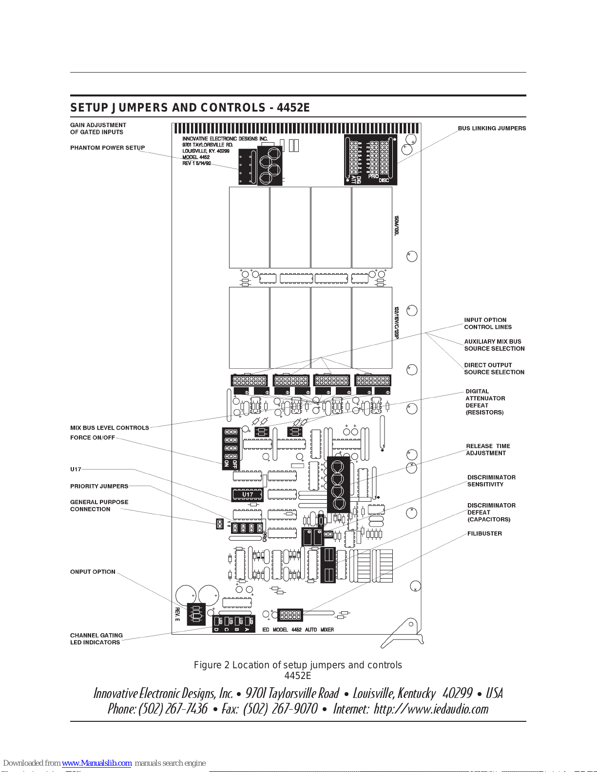
Figure 2 Location of setup jumpers and controls
4452E
SETUP JUMPERS AND CONTROLS - 4452E

4000 SERIES AUTOMATIC MIXER SYSTEM MAY 1998 SECTION 4GROUP 03 SUB BPAGE 3
INSTALLATION INSTRUCTIONS MODEL 4452 AUTOMATIC MIXER
Figure 3 - Location of setup jumpers and controls
4452C
SETUP JUMPERS AND CONTROLS - 4452C

SECTION 4GROUP 03 SUB BPAGE 4MAY 1998 4000 SERIES AUTOMATIC MIXER SYSTEM
MODEL 4452 AUTOMATIC MIXER INSTALLATION INSTRUCTIONS
Innovative Electronic Designs, Inc. 9701 Taylorsville Road Louisville, Kentucky 40299 USA
Phone: (502) 267-7436 Fax: (502) 267-9070 Internet: http://www.iedaudio.com
hh
hh h
Figure 4 - Location of setup jumpers and controls
4452CE
SETUP JUMPERS AND CONTROLS - 4452CE

4000 SERIES AUTOMATIC MIXER SYSTEM MAY 1998 SECTION 4GROUP 03 SUB BPAGE 5
INSTALLATION INSTRUCTIONS MODEL 4452 AUTOMATIC MIXER
Figure 5 - Location of linking jumpers
on the 4452 card
CARD LINKING USING JUMPERS - 4452 AND 4452E ONLY
The 4000 series automatic mixer accomplishes
card-to-card linking by sharing certain informa-
tion between cards. This information can be
fully or partially accessed, dependent on need,
by installing linking jumpers. Refer to figure 5
for the location of the linking jumpers on the
4452 card. The information which can be
shared between cards is referred to as the 5
Linking Options. These options consist of the
following:
1) Discriminator information
2) Priority information
3) Digital Attenuator information
4) Main audio
5) Auxiliary audio
Each mixer card in the Model 4452 Automatic
Mixer Series has four gated inputs. In order to
produce mixers with a greater number of gated
inputs (up to 32 gated inputs in each main-
frame), the mixer cards must be linked. Linking
allows the cards to perform as a single larger
mixer in every respect.
This example makes use of 4452 cards with
Main and Aux outputs. In most systems, a card
group such as that shown in figure would have
only one 4452 card. It would be designated as
the main card, and would be placed in the fur-
thest right position of the group. The remainder
of the cards in the group would be 4452E Ex-
pansion Cards. Expansion cards are more eco-
nomical, since their Main and Aux Outputs,
which are not used, are omitted, as are their
corresponding bus jumpers.
To understand the 4000 Series linking opera-
tion we will select one of the 4452 Automatic
Mixer card inserted in a 4174 mainframe. The
shaded card in Figure 9 will be used as an ex-
ample. When the 4452 automatic mixer card
being discussed is mounted in the 4174 Main-
frame, its 5 Linking Options are available to the
other cards in the mainframe via the 4174 bus
system. Installing a shunt in the #1 position, on
eachlinking option as illustrated in Figure 10 al-
lowsthe4452 to completely link to itself.Focus-

SECTION 4GROUP 03 SUB BPAGE 6MAY 1998 4000 SERIES AUTOMATIC MIXER SYSTEM
MODEL 4452 AUTOMATIC MIXER INSTALLATION INSTRUCTIONS
Innovative Electronic Designs, Inc. 9701 Taylorsville Road Louisville, Kentucky 40299 USA
Phone: (502) 267-7436 Fax: (502) 267-9070 Internet: http://www.iedaudio.com
hh
hh h
Figure 6 - Illustration of relative position numbering
ingonthe Main Audio for example, installing a jumper in the
#1positionallowsthemixedgatedinputstopasstoitsown
Main output.
Inreferringbacktofigure6,theshaded card can access, ei-
therpartiallyorfully,thelinkingoptionsofany orall ofthere-
maining cards.
Figure6 illustrates relative position numbering.Inthe exam-
ple shown, the card in slot 6 is to be jumpered to link it with
the cards in slots 4, 5, 7, and 8, as well as its own output.
Each card, as it is being jumpered, is in relative position 1.
Therefore, a jumper must be placed in position 1 on each of
the five buses in order to link a card to its own buses. Nor-
mally, this is done as a matter of course, but under some
special circumstances it may be useful to omit a jumper. Jumpers must be placed on each of the five buses
foreachoftheothercards tobelinked,usingtheirrelativeslotpositions. Sincetherearecardsinrelativepo-
sitions 1, 2, 3, 7, and 8, for complete linking, there must be jumpers in positions 1, 2, 3, 7, and 8 on each of
the five buses. Figure 7 illustrates the complete jumpering for the card in slot 6. Figure 8 illustrates the
jumper placement for complete linking of all cards in the group.
Figure 7 - Jumpering for the card in slot 6
in Figure 9 above

4000 SERIES AUTOMATIC MIXER SYSTEM MAY 1998 SECTION 4GROUP 03 SUB BPAGE 7
INSTALLATION INSTRUCTIONS MODEL 4452 AUTOMATIC MIXER
Figure 8 - Jumper placement for all cards in the group

SECTION 4GROUP 03 SUB BPAGE 8MAY 1998 4000 SERIES AUTOMATIC MIXER SYSTEM
MODEL 4452 AUTOMATIC MIXER INSTALLATION INSTRUCTIONS
Innovative Electronic Designs, Inc. 9701 Taylorsville Road Louisville, Kentucky 40299 USA
Phone: (502) 267-7436 Fax: (502) 267-9070 Internet: http://www.iedaudio.com
hh
hh h
PHANTOM POWER SETUP
Phantom power can be enabled or disabled
on each gated input as required. As shipped
from the factory, phantom power is disabled
for all line level inputs (options 0-4), and en-
abled for all microphone level inputs (options
5-9).
If all the gated inputs are microphone level
(options 5-9), then phantom power is en-
abled on all inputs as in “A” below. There are
nojumpers installedatC1A-C1D and a100
W
,8
pin isolated single-in-line (SIP) resistor pack-
age is installed at RS19. This SIP has 4 indi-
vidual 100
W
resistors, each providing
phantompowertoitsrespectivegatedinput.
If all the gated inputs are line level (options
0-4), then phantom power is disabled on all
inputs as in “B” below. There are 4 jumpers
installed at C1A-C1D and no resistors or SIP in-
stalled at RS19. These jumpers terminate the
line level input module (100L). Without these
jumpers the audio will eventually become
distorted.
If the gated inputs are a combination of line
level (options0-4)andmicrophone level
(options 5-9), then phantom power is en-
abled for the microphone level inputs and
disabled for line level inputs. For line level in-
puts, a jumper is installed at the proper loca-
tion of C1A-C1D, and nothing in the
corresponding location of RS19. For micro-
phonelevelinputs,an individual resistor is in-
stalled at the proper location of RS19 for that
input and nothing at C1A-C1D. The individual
resistor is a 100
W
,14watt, 5% installed with
one end of the resistor standing up. In exam-
ple “C” below, inputs A and D are micro-
phonelevelandinputsBandCarelinelevel.
Figure 9 - Enabling phantom power

4000 SERIES AUTOMATIC MIXER SYSTEM MAY 1998 SECTION 4GROUP 03 SUB BPAGE 9
INSTALLATION INSTRUCTIONS MODEL 4452 AUTOMATIC MIXER
GAIN ADJUSTMENT OF GATED INPUTS
Gated Inputs - For line level options (input
options0-4)thegain range of the gated in-
putsis-2 dB to +18 dB.Fortheseoptionsthe
gain is factory preset at minimum (-2 dB).
For the microphone level options input (op-
tions5-9)thegain range of gated inputs is
+26 dB to +46 dB. It factory preset at ap-
proximately 35 dB.
To change the gain, rotate the pot for the de-
sired input, clockwise to increase or counter-
clockwise to decrease. See the figure at the
left and the detail below.
For input options which make use of the
Model 120P, its gain must be forced to maxi-
mum before adjusting the input gain. This is
accomplished by placing a jumper on Con-
trol 1 for the appropriate input. See figure 8,
page 7. After making the desired adjustment,
remove the jumper.
Figure 10 - Gain adjustment of gated inputs

SECTION 4GROUP 03 SUB BPAGE 10 MAY 1998 4000 SERIES AUTOMATIC MIXER SYSTEM
MODEL 4452 AUTOMATIC MIXER INSTALLATION INSTRUCTIONS
Innovative Electronic Designs, Inc. 9701 Taylorsville Road Louisville, Kentucky 40299 USA
Phone: (502) 267-7436 Fax: (502) 267-9070 Internet: http://www.iedaudio.com
hh
hh h
INPUT OPTION CONTROL LINES
^F:\4_03B\INOPCTRL.SFP^ TheInputOption ControlLines arefactoryset
according to the input option selected and
should not be changed. Refer to the figure
below for details of jumper setup.
The table below shows which control line
must have a jumper in place for each input
option.
OPTION
NUMBER INPUT
MODULE CONTROL
LINE
0 None None
1 110V 2
2 120P None
3 132 1
4 110C None
5 None None
6 110V 2
7 120P None
8 132 1
9 110C None
When setting or changing the gain of a chan-
nel which makes use of the 120P, options 2
and 7, a jumper must be placed temporarily
to select control line 1 while the gain is being
adjusted. This forces the 120P to maximum
gain.Thejumper isremovedaftercompleting
the adjustment.
Figure 11 - Setting input option control jumpers

4000 SERIES AUTOMATIC MIXER SYSTEM MAY 1998 SECTION 4GROUP 03 SUB BPAGE 11
INSTALLATION INSTRUCTIONS MODEL 4452 AUTOMATIC MIXER
AUXILIARY MIX BUS SOURCES
The Auxiliary Output mix can be sourced from
one of three points for each gated input. The
three points are Pre Input Option, Post Input
Option, and Post Gate. The selection is made
by the placement of jumpers. Refer to the fig-
urebelow forthe detailsofjumper setup.When
shipped from the factory, there is a jumper in
the Post Gate position for each input.
The Pre Option selection feeds the input signal
priortoinput processingtotheAuxiliaryOutput
mix bus. Input processing refers to the se-
lected input option. The output level of the in-
put module must be
â
0 dBu, or clipping will
occur.
The Post Option selection feeds the input sig-
nal to the Auxiliary Output mix bus after it has
received input processing, but before it is
gated.
The Post Gate selection feeds the input signal
to the Auxiliary Output mix bus after it has re-
ceived input processing and after it pases
throughthe gating switch. This is the same sig-
nal which is fed to the Main Output mix bus.
Neverinstall jumpersin morethanone position
for the pre-option, post option, or post gate
setup.
Figure 12 - Selecting the Auxiliary mix bus source

SECTION 4GROUP 03 SUB BPAGE 12 MAY 1998 4000 SERIES AUTOMATIC MIXER SYSTEM
MODEL 4452 AUTOMATIC MIXER INSTALLATION INSTRUCTIONS
Innovative Electronic Designs, Inc. 9701 Taylorsville Road Louisville, Kentucky 40299 USA
Phone: (502) 267-7436 Fax: (502) 267-9070 Internet: http://www.iedaudio.com
hh
hh h
DIRECT OUTPUT SOURCE SELECTION
The Direct Output can be sourced from the
Aux mix bus feed, the Main mix bus feed, or it
may be Off for each gated input. The selec-
tion is made by the placement of jumpers.
Refer to the figure below for the details of
jumper setup. When shipped from the fac-
tory, there is a jumper in the Main mix bus
feed position for each input.
The Aux mix bus feed selection feeds the in-
put signal to the Direct Output from the wiper
of the Aux mix bus pot for that input. Prior
processing depends on the placement of the
Aux Source selection jumper.
TheOffselectionfeedsnosignal to the Direct
Output by grounding the input to the Direct
Output op amp.
The Main mix bus feed selection feeds the in-
put signal to the Direct Output after it has re-
ceived input processing and after it pases
through the gating switch and the mix bus
pot.This isthesame signal whichis fed tothe
Main Output mix bus.
Never install jumpers in more than one posi-
tion for the Aux Source, Off, or post gate
setup.
Figure 13 - Selecting the Direct Output source

4000 SERIES AUTOMATIC MIXER SYSTEM MAY 1998 SECTION 4GROUP 03 SUB BPAGE 13
INSTALLATION INSTRUCTIONS MODEL 4452 AUTOMATIC MIXER
MAIN AND AUXILIARY MIX BUS LEVEL CONTROLS
The Main and Auxiliary Mix Bus level controls
are multi-turn pots. There is one pot for each
input on each bus, for a total of eight pots.
See the detail below for the location of each
pot.
Level is increased by clockwise rotation, or
decreased by counterclockwise rotation.
Levels can be adjusted over the range of no
attenuation to -80 dB.
When shipped from the factory, the Main Mix
busissetat-14dB, andtheAux mixbusisset
at -10 dB.
Figure 14 - Setting the Main and Auxiliary Mix Bus levels

SECTION 4GROUP 03 SUB BPAGE 14 MAY 1998 4000 SERIES AUTOMATIC MIXER SYSTEM
MODEL 4452 AUTOMATIC MIXER INSTALLATION INSTRUCTIONS
Innovative Electronic Designs, Inc. 9701 Taylorsville Road Louisville, Kentucky 40299 USA
Phone: (502) 267-7436 Fax: (502) 267-9070 Internet: http://www.iedaudio.com
hh
hh h
RELEASE TIME ADJUSTMENT OF GATED INPUTS
Release Time - The release time is the time a
gated input remains on after the input signal
is removed. It should be set sufficiently long
so that normal pauses in speaking will not
cause the input to gate off. Release Time is
factory preset to approximately 2.5 seconds,
a time suitable for most typical speakers. For
a speaker with different speech habits or
style, it may be necessary to make adjust-
ments. It can be set anywhere within the
range of 0.5 to 8 seconds. Setting is accom-
plished by means of trimpots which may be
accessed by use of the Model 4000 Card Ex-
tender or by removing the card from the
frame. Details are shown in the figure below.
Turning the release time control clockwise
willdecrease the release time, causing thein-
put to turn off faster. Turning the release time
control counterclockwise will increase the re-
lease time, causing the input to turn off
slower.
Figure 15 - Release time adjustment of gated inputs

4000 SERIES AUTOMATIC MIXER SYSTEM MAY 1998 SECTION 4GROUP 03 SUB BPAGE 15
INSTALLATION INSTRUCTIONS MODEL 4452 AUTOMATIC MIXER
MAIN AND AUXILIARY OUTPUT LEVEL ADJUSTMENT
The Main and Auxiliary Output level controls
adjustthe levelsof theMainand Auxiliaryout-
puts. These controls are full range attenua-
tors. Their range is 0 dB at the maximum
setting (full clockwise) to approximately
-85 dB at the minimum setting (full counter-
clockwise).
When shipped from the factory, the Main out-
put level control is set at approximately 6 dB
of attenuation, and the Auxiliary output is set
at maximum output, 0 dB of attenuation.
Figure 16 - Setting Main an Auxiliary output levels

SECTION 4GROUP 03 SUB BPAGE 16 MAY 1998 4000 SERIES AUTOMATIC MIXER SYSTEM
MODEL 4452 AUTOMATIC MIXER INSTALLATION INSTRUCTIONS
Innovative Electronic Designs, Inc. 9701 Taylorsville Road Louisville, Kentucky 40299 USA
Phone: (502) 267-7436 Fax: (502) 267-9070 Internet: http://www.iedaudio.com
hh
hh h
FORCE ON OR FORCE OFF OF GATED INPUTS
Force On/Force Off - These functions over-
ride gating operation and place the input in a
continuous ON state or a continuous OFF
state, respectively. When an input is forced
on it still contributes to the attenuation of the
Main Output (Digital Attenuator), to the Fili-
bustercount,and to the Discriminator,unless
specifically removed from these functions by
defeating the Digital Attenuator and/or the
Discriminator (see pages 21 and 22).
When an input is forced off, it still contributes
to the Discriminator, unless specifically re-
moved from this function by defeating the
Discriminator (see page 22).
For details of jumper setup, refer to the figure
below.
The 4452 Series Automatic Mixers are
shippedfromthefactorywithallinputssetfor
normal gating (no jumpers installed).
Figure 17 - Force On and Force Off for gated inputs
Jumper setup

4000 SERIES AUTOMATIC MIXER SYSTEM MAY 1998 SECTION 4GROUP 03 SUB BPAGE 17
INSTALLATION INSTRUCTIONS MODEL 4452 AUTOMATIC MIXER
ENABLING/DISABLING PRIORITY OF GATED INPUTS
Priority - Priority is the feature, which when
enabled for an input allows that input to take
precedence over inputs which do not have
thepriority featureenabled.That isto saythat
when an input in priority is gated on, other in-
puts not in priority are immediately caused to
gate off. Other inputs which are in priority are
not affected. To place an input in priority,
place a jumper on the appropriate pins as
shown in the figure below. As shipped from
the factory, no priority jumpers are in place,
and no inputs are in priority.
Figure 18 - Enabling/disabling Priority of gated inputs

SECTION 4GROUP 03 SUB BPAGE 18 MAY 1998 4000 SERIES AUTOMATIC MIXER SYSTEM
MODEL 4452 AUTOMATIC MIXER INSTALLATION INSTRUCTIONS
Innovative Electronic Designs, Inc. 9701 Taylorsville Road Louisville, Kentucky 40299 USA
Phone: (502) 267-7436 Fax: (502) 267-9070 Internet: http://www.iedaudio.com
hh
hh h
FILIBUSTER LIMIT SET OF GATED INPUTS
Filibuster - The Filibuster feature limits the
maximum number of inputs which can gate
on in a given mixer. If mixers are combined or
linked, the total number of inputs which are
gated on in the combined or linked mixer
count toward the limit. The limit can be set at
1, 2, 3, 4, or ALL on each mixer card. The ALL
setting defeats the feature. If mixers are com-
bined or linked and the limit on a particular
mixer is set for 2, an input on that mixer can
gate on only when the total number of inputs
which are on on all mixers in the group is less
than 2.. A jumper MUST be placed in one,
but not more than one of the positions, or
erratic performance may result. The figure
below shows the details of jumper place-
ment. Inputs for which the Digital Attenuator
has been defeated do not contribute to or af-
fect the Filibuster limit, although they are still
subject to it. As shipped from the factory,
there is a jumper in the ‘All’ position, defeat-
ing the Filibuster feature.
Figure 19 - Filibuster limit set of gated input
Jumper setup
This manual suits for next models
3
Table of contents
Popular Mixer manuals by other brands

Electrolux
Electrolux EKM3407K Instruction book

Cornell
Cornell CSM-EL688B user manual

Glas-Col
Glas-Col 099A LC1024CE Use instruction

Amperes
Amperes MX2322 instruction manual

Wolfgang Puck
Wolfgang Puck BMSD0020 Signature Collection manual

Universal Trade Supplies
Universal Trade Supplies CPL 60 instruction manual