Innovative Neurotronics The WalkAide System Instructions for use

The WalkAide®System
Clinician Manual
INDEPENDENCE
one step at a time
Caution: USA Federal Law restricts this device to sale by or on the order of a physician.
LM06-R6
© 2013 Innovative Neurotronics. All rights reserved. All trademarks and registered trademarks
are the property of their respective holders. No part of this manual may be reproduced in any
form without the written consent of Innovative Neurotronics Incorporated. Information in this
manual is for the use of qualified clinicians only.

EC REP
Medical Device & QA Services
76, Stockport Road
Timperley, Cheshire
WA15 7SN
United Kingdom
Tel: 44 161 870 6751
e-mail: [email protected]
0086
1.0 Introduction 2
1.1 Indications of Use 2
1.2 Contraindications 3
1.3 Warnings About FES 3
1.4 WalkAideSpecicWarnings 4
1.5 Precautions 5
1.6 Regulatory Information 5
1.7 Adverse Reactions 6
1.8 Cautions 6
1.9 Glossary 6
2.0 Equipment 10
2.1 Clinician Kit 10
2.2 Patient Kit 11
2.3 Demo Kit 11
2.4 WalkAide/WalkLink Controls, Indicators & Alarms 12
2.5 WalkAide Bi-Flex Cuff 13
2.6 Electrode Replacement 14
2.7 WalkAide Cuff Disposable Liner 15
2.8 SymbolsandDenitions 16
3.0 WalkAnalyst Software 16
3.1 Installation 16
3.2 WalkAnalyst Upgrades 17
3.3 Administration 17
3.4 Changing Clinical Preferences 18
3.5 Backup 18
4.0 WalkLinkCongurationandBluetoothPairing 19
4.1 Conguringinitialset-upprocess(Pairing) 19
5.0 FittingProcess 20
5.1 Pre-screening with the Peripheral Nerve Stimulator 20
5.2 Electrode Placements and System Preparations 22
5.3 Fitting a New Patient 25
5.4 Fitting a Returning Patient 25
5.5 Programming Options 26
5.5.1 Rapid+ Program 26
5.5.2 Standard Program 29
5.5.3 Adjustment 32
5.5.4 Recover Program 33
5.5.5 Transfer Program 33
5.6 Exercise Mode Settings 34
5.7 Wearing Schedule 35
5.8 Usage Log 36
6.0 Evaluation&Reporting 37
7.0 UseandCareoftheWalkAideandAccessories 39
7.1 Care and Use of WalkAide Electrodes 39
8.0 ClinicalTroubleshooting 40
8.1 Electrode Placement Best Practice 40
8.2 Manual Adjustment of the Stimulation Settings 41
8.3 Graph Analysis 46
8.4 Follow-Up and Re-Optimization 47
9.0 TechnicalTroubleshooting 49
9.1 WalkAide Troubleshooting 49
9.2 WalkLink Troubleshooting 51
9.3 Alternate Pairing Method 52
9.4 Bluetooth USB Troubleshooting 52
10.0 WalkAide User Manual 53
11.0 TechnicalInformation 54
12.0 Contact Information 55
2
3
1.0 Introduction
The WalkAide is a battery-operated, single-channel electrical stimulator that can be used for
functionalelectricalstimulation(FES).Itutilizesatiltsensorandaccelerometertocontrol
the timing and duration of the stimulation during walking. A hand switch on the WalkLink is
used by the clinician during set-up to manually trigger stimulation. The clinician uses the
WalkAnalyst software on a laptop computer to program the tilt sensor in the WalkAide. Use of
the Tilt Sensor to trigger stimulation eliminates the need for additional components or external
wires.
TheWalkAideproducescontrolleddorsiexionofthefootduringwalk.Thissmallmedical
deviceattachestoamoldedcufflocatedjustbelowtheknee.Twoelectrodesarespecically
placed over the motor nerve and proximal musculature. During the gait cycle, the WalkAide
stimulates the common peroneal nerve which innervates the tibialis anterior and other
musclesthatproducedorsiexionoftheankle.Candidatesincludepeoplewhohavelostthe
ability to voluntarily lift their foot during walking, often as a result of damage to the central
nervous system from conditions such as stroke, incomplete spinal cord injury, traumatic brain
injury, cerebral palsy and multiple sclerosis. This type of stimulation will not work for people
who have damage to the lower motor neurons/peripheral nerves.
1.1 Indications of Use
The Innovative NeurotronicsWalkAide System is intended to address foot drop for people
who have sustained damage to upper motor neurons in the brain or the spinal cord. Medical
benetsoffunctionalelectricalstimulationmayincludeadecreaseinmuscledisuse,
decreasedmuscleweakness,increasedlocalbloodow,improvedmusclestrengthand
voluntary motor control, increased joint range of motion, and enhanced function of the
corticospinal pathways resulting in improved lower limb control.
1.2 Contraindications
Donotuseonpersonswithimplanteddemandtypecardiacpacemakersordebrillators.•
Donotplacetheelectrodesinthecarotidsinusregion(throat).Laryngealorpharyngeal•
spasms may occur when the electrodes are placed across the throat or in the mouth.
Do not place the electrodes over malignant tumors.•
Do not place the electrodes over areas in which symptoms of existing thrombosis are•
present.
Do not use if person has a history of seizure disorder.•
1.3 WarningsAboutFES
MonitoringEquipment - The use of FES may interfere with the proper functioning of
electronic monitoring equipment such as EKG machines. However, the operation of the FES
device will not be affected by the use of electronic monitoring equipment.
MRI - The WalkAide should not be worn while receiving any MRI scan.
Electrodes - The use of electrodes not supplied by Innovative Neurotronics may diminish
results or increase risk of burns or discomfort. Do not place electrodes over open wounds,
broken skin or metal objects beneath the skin such as surgical staples.
Pregnancy - The safety of FES for use during pregnancy has not been established.
Hospital Equipment - Do not use simultaneously with high frequency hospital equipment
(e.g.diathermyequipment).Itmayresultinburnsatthesiteofthestimulatorelectrodesand
possible damage to the stimulator.
Skin Irritation - Improper or prolonged use of electrodes may result in increased risk of skin
irritation or burns and decreased effectiveness. Infrequently, there is an allergic response
to the electrode adhesive or gel. Do not place electrodes on skin that is already irritated as
this will increase the risk of discomfort with stimulation and the risk of further skin irritation or
burns.
Medical Supervision - FES should only be used under the medical supervision of a physician
andaqualiedclinician.
Two-Way Radios-CareshouldbetakenwhileusingFEStherapyincloseproximity(e.g.
lessthan1meter)todeviceswhichemitradiofrequenciessuchascellularphonesortwo-way
radios as some types of transmitters may cause undesirable stimulation to the user.
Figure 1: The WalkAide System

4
5
Debrillator-ExternaldebrillationofapersonwearingaFESdevicecandamagethe
device or injure the user even when the device is turned off. Under some circumstances there
mayberiskofburnsundertheelectrodesitesduringdebrillation.Toeliminateanyrisk,the
FESelectrodesshouldberemovedbeforedebrillationpaddlesareapplied.
ChronicStimulation - Effects of long term chronic stimulation are unknown in this particular
application.
1.4 WalkAideSpecicWarnings
Walking - Care should be taken when using the WalkAide for people who experience
dizzinessorhavedifcultymaintainingbalance.TheWalkAideisnotdesignedtoprevent
falling. Assess user’s condition for inability to walk or balance.
Electrodes - The user should not relocate the position of the electrodes within the cuff. Do
not use the WalkAide without electrodes.
Placement - Never use the WalkAide on any area of the body other than the leg.
Stimulation - Stop using the WalkAide if stimulation does not come on at the appropriate time
when walking and/or there is a change in the sensation perceived while the stimulation is on.
Environment-WalkAideandWalkLinkarenotintendedforusewithinammable
environments such as oxygen and anesthetics.
Impact - Care should be taken to prevent excessive impact to the WalkAide Control Module.
This includes standing or kneeling on the unit, or impact from any hard surfaces.
WalkLink
1. FCC Part 15 notice:
This device complies with Part 15 of the FCC Rules. Operation is subject to the following
twoconditions:(1)Thisdevicemaynotcauseharmfulinterference,and(2)thisdevice
must accept any interference received, including interference that may cause undesired
operation.
2. FCC Radiation Exposure Statement for Portable Devices
This equipment complies with FCC radiation exposure limits set forth for an uncontrolled
environment. This equipment is in direct contact with the body of the user under normal
operating conditions. This transmitter must not be co-located or operating in conjunction
with any other antenna or transmitter.
3.Theuseriscautionedthatchangesormodicationsnotexpresslyapprovedbytheparty
responsible for compliance could void the user’s authority to operate the equipment.
1.5 Precautions
Heart Disease - Use caution in applying electrical stimulation to persons suspected of having
heart disease. More clinical data is needed to show that such persons will not experience
adverse results.
Sensory Deprivation - Use caution when placing electrodes on areas of the skin with
reduced response to normal sensory stimuli, due to the risk of skin burns.
Children - FES devices should be kept out of the reach of children.
Epilepsy - Use caution in applying electrical stimulation to persons suspected of having
epilepsy. More clinical data is needed to show that such a person will not experience adverse
events.
RecentSurgery - Do not use FES following recent surgery where muscle contraction may
disrupt the healing process.
Electrodes - Do not use lotion or oil in the area that the electrodes make contact with the
skin. Stimulation may not be effective.
ProperUse-ThesafetyandefcacyofFESdependsontheproperuseandhandlingof
the FES system. Improper use of the device or electrodes can result in injury to the user.
Regularlycheckaccessoriesforwearandreplaceasneeded.Electrodesshouldbermly
secured to the skin. Never use the WalkAide if it appears to be malfunctioning. If there
isachangeinthewayitusuallyworks(i.e.changeinsensation,surgingofstimulation,
intermittentstimulation)donotusetheWalkAideandcontactInnovativeNeurotronics
immediately.
OperatingEquipment - The stimulator should not be used while operating potentially
dangerous equipment such as automobiles, power lawn mowers or large machinery. Abrupt
changes in stimulation level could create a hazard.
Sleeping - The WalkAide should not be worn or used while sleeping or bathing.
Heat and Cold - The use of heat or cold producing devices such as electric blankets, heating
pads or ice packs may affect the electrodes or the person’s circulation and increase the risk of
injury. A medical doctor and clinician should be consulted before using with FES.
Caution - Do not plug foot sensor into any electrical socket other than WalkAide.
Caution - Do not unplug foot sensor while sensor is in the shoe.
1.6 RegulatoryInformation
FDA is the regulatory agency that governs the process of testing and approval of medical
devices.TheWalkAidehasbeenclassiedasaClassIImedicaldevice,requiringFDA
510(k)approvalofdevicesafetyandtheeffectivenessofthedevicepriortomarketing.

6
7
InnovativeNeurotronicssubmittedthe510(k)toFDAwhichcontainedextensivetestingand
designdata,andsuccessfullyreceived510(k)approvalon09/21/05.
1.7 Adverse Reactions
Skin irritation and burns beneath the electrodes have been reported with the use of nerve
stimulators. Do not leave the electrodes in place for long periods of time without checking or
cleaning the skin underneath them. It is normal to observe somewhat reddened areas under
the electrodes immediately following use; however, the redness should disappear within an
hour. Signs of irritation are maintained redness, small pimple-like lesions or blisters. DO
NOT continue stimulation over irritated skin. Notify the medical doctor if these conditions
persist and and discontinue use of the WalkAide until the problem is resolved.
1.8 Cautions
Functional electrical stimulation is the process of using electrical stimulation to produce
a muscle contraction during a dynamic activity, such as walking. Basic rules of FES use
include:
1. ALWAYSusetheWalkAideunderthespecicinstructionofanexperiencedclinician.
2. NEVER use the WalkAide in a situation where an unexpected or unusual stimulus may
occur, such as driving or operating motorized equipment.
3. DO NOT use the WalkAide if the equipment is not operating properly.
4. NEVER use the WalkAide unit with frayed or broken leads.
5. ALWAYS handle the unit carefully…do not expose the unit to water, excessive heat or
vibration.
6. DO NOT place electrodes anywhere other than on one leg below the knee, as instructed
by clinician.
7. AVOID excessive impact, dropping or kneeling on the WalkAide unit. Although robustly
designed, damage may occur that could cause the unit to malfunction.
8. The WalkAide should ONLY be used with approved accessories and electrodes.
9. DO NOT open the unit other than to replace the battery. The WalkAide has no user or
clinician serviceable parts inside the control module enclosure.
10. TURN OFF the unit if sitting for an extended period of time.
1.9 Glossary
AutosetWalkAideParameters
This calculation process adjusts the threshold settings to more closely match the individual
data collected.
AudibleBeep
Optional Biofeedback Feature. Audible signal can be activated to indicate when the stimulus
is on. Hold the middle button down and turn the WalkAide on by turning the blue knob.
CollectWalkingData
Collects patient walking data from the Heel Sensor, Hand Switch and/or Tilt Sensor during:
(1)initialdatacollectionprocedures,(2)programmedwalkingtrialsineitherTiltorHeel
mode,and(3)follow-upwalkingtrialsforconrmationofeffectivewalkingprogramsorre-
optimization.
CollectedLogs
Saved Usage Logs listed as date and time stamped events.
Comments
Allowsthecliniciantodocumentclinicalnotesintheuser’selectronicle.
Control Times
Adjustthedurationofthestimulation(MinandMaxTimes);pausingofthestimulation(Wait
Time);andinitiationandterminationofthestimulation(RampOn,RampOff).
Bi-FlexCuff
Pretibial shell that attaches to the leg and is used to hold the electrodes and the WalkAide
control module in the correct position.
DefaultSettings
A pre-determined set of parameters that must always be sent to the WalkAide before
collection of initial walking data for a new user.
Delete
Deletes entire walking trial.
ExerciseMode
Allowstheusertorepeatedlystimulatethelowerlegwhiletheuserissitting(NOTwalking)for
a set period of time as determined by the clinician.
ExerciseSettings
Allows the clinician to adjust the ON time, OFF time and duration of the Exercise Mode
function for the individual user.
FilterParameter
A calculation function that attempts to smooth ‘noisy’ data; and can also delay or accelerate
the onset of the stimulation. Filter parameters need to be applied prior to collecting walking
data.
Functional Electrical Stimulation (FES)
A method of applying a low level of electrical impulses to the motor nerve to activate
dysfunctional muscles and produce intentional and useful movement.
HandSwitch
A function of the WalkLink whereby pressing the STIM button on the WalkLink sends a
command to the WalkAide unit to provide stimulation when the WalkAide is programmed in
Hand Mode.

8
9
Heel and Foot Sensors
There are two types of load bearing sensors:
(1) Theclinicianheelsensorisusedduringdatacollectionandanalysiswhiletestinga
potential WalkAide user.
(2) Theoptionalfull-lengthfootsensorissenthomewithuserswhosegaitpatterndoes
notprovidesufcienttiltinformationtoreliablytriggerthestimulationwiththetiltsensor.
ModiedParameters
Walking parameters that are associated with or derived from the WalkAide unit, Heel Sensor
and/orHandSwitchafterdatacollectionandprocessinghaveoccurred(e.g.Zoom,Autoset,
Optimize,ormanualadjustments).
CreatePatientProle
Createsanewleforanewpatient.
OpenaPatientProle
Opensanexistingleforanexistingpatient.
OptimizeGaitProgram
Function of the WalkAnalyst software that computes features of the collected walking data
andcongurestheONandOFFthresholdsandotherparameterstooptimizethetimingand
duration of the stimulation for the individual’s gait.
PeripheralNerveStimulator
Determines the viability of the nerve to muscle pathway and allows accurate location of the
peripheralnerves,specicallythesupercialanddeepbranchesofthecommonperoneal
nerve, for placement of electrodes.
Adjustment
Settings that allow Rapid Follow-Up-Fine adjustments.
Rapid+Programming
Rapid data collection and programming. Default settings are Tilt mode.
ResetUsageLog
Resets the “Hours Per Day” and “Stims Per Day” tracking functions.
Reset Zoom/Unselect
Reverses selection function, returning to the original data set and entire walking sequence.
RetrieveUsageLog
DownloadsUsageLogfollowingtting/programmingoftheWalkAide-First69daysof“Hours
Per Day” and “Stims Per Day” information since log was last cleared.
RestoreOriginal
Reverses Autoset / Optimize functions and manual adjustments, returning thresholds and
control times to original values.
Save and Analyze
Function that saves and adds the current walking trial as a date and time stamped event
under Collected Walking Trials.
Save Copy
Saved WalkAide settings listed as date and time stamped events.
Send to WalkAide
Onthewalkingdatagraphscreenoronthemodiedparameterscreen,allowstheclinician
to send parameters to the WalkAide unit using the WalkAnalyst software and Bluetooth
connection.
STIM
Abbreviated form of the word stimulation.
Stimulation Mode
Allows the clinician to select from Heel, Hand or Tilt to trigger the stimulation during walking.
StimulusSetting
Allows the clinician to adjust the characteristics of the pulses within the stimulus train.
Adjustments include Pulse Width, Time Between and Extra Stimuli functions.
UsageLogs
CollectsWalkAideusageinformation,specicallyHoursPerDayandStimsPerDay,for69
days of walking activity since the usage log was last cleared.
WalkingDataThresholds
Determine the timing of the initiation and termination of the stimulation for either the Heel or
Tilt sensors.
WalkAide
A battery-operated, single channel electrical stimulator that can be used for both therapeutic
and functional electrical stimulation.
WalkAideDiagnosticCodes
Six digit readout indicating WalkAide System hardware’s internal status / fault.
WalkAideSettings
Walking parameters currently programmed into the WalkAide unit.
WalkAide Serial Number
Automatically logs and registers the serial number from the WalkAide unit on the WalkAide
Parameters screen. The serial number can also be found in the battery compartment of the
WalkAide.
WalkAnalyst
Software used by the clinician to interface with the WalkAide unit. This allows data collection,
10
11
analysisandparametermodicationinordertocorrectlytimetheappliedstimulationtothe
user.
WalkLink
Provides a wireless connection between the WalkAide and a computer, and also allows
manual stimulation during walking trials via the Hand Switch.
Zoom/Select
Allowsthecliniciantofocusonspecicdatabyhighlightingasequenceofconsecutivesteps
with the stylus or mouse.
2.0 Equipment
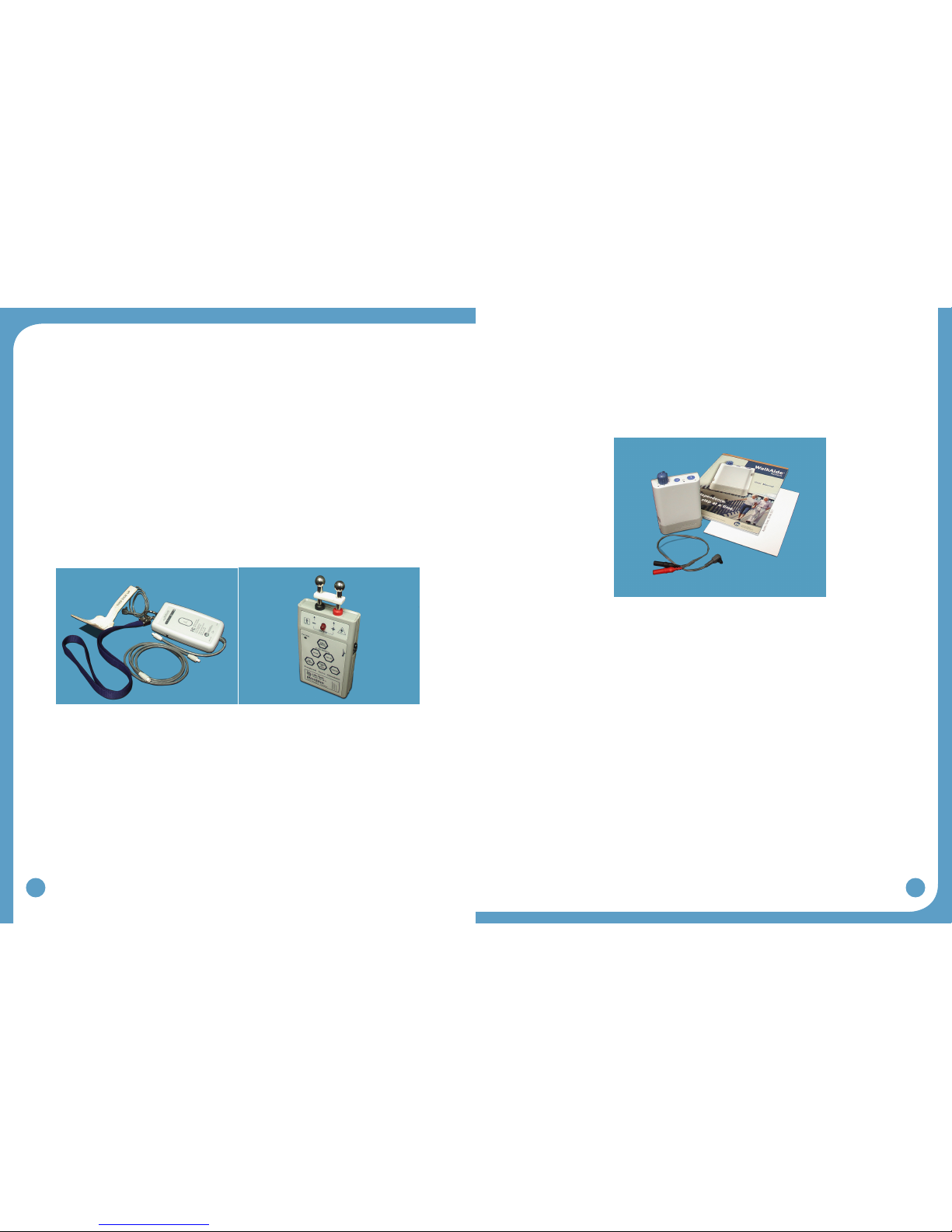
2.1 Clinician Kit
The Clinician Kit consists of the WalkLink, WalkLink Cable, Heel Sensor, Bluetooth adapter,
WalkAnalystsoftware,andtheWalkAnalystSystemClinicianManual(Figure2).The
WalkLinkrequiresfour(4)AAbatteries.
It is recommended to have a computer that meets or exceeds the following requirements:
1.5 GHz processor•
512MBRAM(XP)/1GBRAM(WindowsXPorWindows7)•
200Mb free hard drive space•
XGA(1024x768)video•
One free USB port for the Bluetooth Adapter•
WindowsXPwithSP2+,orWindows7•
A peripheral nerve stimulator can be purchased separately. The peripheral nerve stimulator
uses a 9-volt battery to operate.
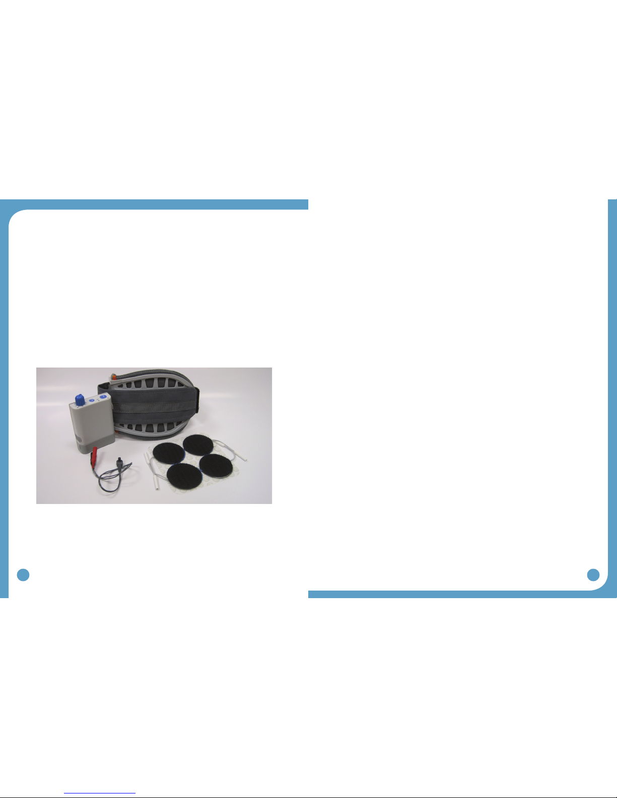
2.2 PatientKit
The Patient Kit consists of the WalkAide Control Module, WalkAide Electrode Lead Cable,
and WalkAide User Manual. An appropriately sized WalkAide Cuff is ordered separately and
the full-length Foot Sensor is an optional item. The WalkAide requires a single AA battery.
OnlyAAalkaline(1.5V)batteriesshouldbeusedandextrabatteriesshouldalwaysbe
available during follow-up appointments.
2.3 Demo Kit
The Clinician Demo Kit consists of the same equipment found in the Patient Kit. However,
the serial number of the WalkAide unit is listed and tracked as a demo unit. It is used for
trial walking on any number of patients, but cannot be sold to a patient as it becomes a used
medicaldevice.(Figure4)
Figure 2: WalkAide Clinician Kit Figure 3: Peripheral Nerve Stimulator
Figure 4: WalkAide Patient Kit

12
13
2.4 WalkAide/WalkLink Controls, Indicators & Alarms
Alarms:
1. Low Battery: An audible alarm of two long beeps every minute with red and green
blinking lights indicate low power condition. Change battery.
2. Heel/Foot Sensor: An audible alarm of two beeps every two seconds indicates that Heel/
FootSensorisnotconnected,whenWalkAideisconguredfortheHeel/FootSensor.
Connect the heel switch or change the mode in WalkAnalyst to Hand / Tilt.
3. Device Error: An audible alarm of four beeps every two seconds with red blinking light
indicates an internal fault. Resend the WalkAide Parameters to the WalkAide. Turn unit
OFF,wait5seconds,turnbackON.Greenpowerlightshouldashandredalertshould
begone.Iftheredlightremainson,contactthedistributor.(Badprogramchecksum)
4. Device Error: An audible alarm of three beeps every two seconds with red and green
blinking lights indicates an internal fault. Resend the WalkAide Parameters to the
WalkAide.TurnOFFunit,wait5seconds,turnbackON.Greenpowerlightshouldash
andredalertshouldbegone.Iftheredlightremainson,contactthedistributor.(Bad
datachecksum)
5.Rapidbeeping:Constantbeepingwithrapidgreenlightashingindicatestheunitwas
turned on too quickly to a high level, or a new battery was installed without turning off the
device. Just turn the device OFF and back ON slowly.
6. Hibernation mode: A non-audible alarm with only a red blinking light indicates hibernation
mode. Establish a Bluetooth connection with WalkAnalyst to automatically clear
hibernation mode. If the hibernation mode does clear, also clear the usage log from the
standard program usage log link.
2.5 WalkAideBi-FlexCuff
The WalkAide is designed for single-handed application and removal. It may take practice
to develop a routine that works best for each person. The WalkAide is applied directly to the
legandcanbeeasilywornundermostclothing.Theclinicianwillndtheoptimalplacement
of the electrodes on the initial visit. The electrode placement will be marked on the inside of
the cuff via Red and Black Electrode Locators and the position should not be moved by the
patient.
Power Indicator
WalkLink STIM button
(HandSwitch)
Low Battery Indicator
Bluetooth Connection
Indicator
Unpair button
ON/OFF
Switch
1
2
Red visual indicator for error
and low battery voltage
Green blinking light indicates that
power is on with
adequate battery power
Amber blinking
light indicates the
presence of STIM
STIM Button Intensity and ON/OFF Knob
Exercise Button
Figure 8 Figure 9
Figure5:TopviewofWalkAideunit(Controls&Indicators)
Output Connector
for Electrode Lead
Cable
WalkLink Connector
[for clinician use only]
Battery Compartment for
standard AA
alkaline battery
Heel [for clinician use only]
or Foot Sensor Connector
[if provided to user]
Back Left side Right side
Front
Figure 6: Back, side and front views of WalkAide unit
Figure7:FrontandsideviewsofWalkLinkunit(Controls&Indicators)

14
15
Thecuffmustbepositionedonthelegcorrectlytoachieveeffectiveandefcientstimulation.
Use the Orange visual indicator as a reference for accurate placement of the cuff. Only use
thelatchtosecureandremovetheWalkAide.TheVelcrostrapisadjustedtoanoptimallevel
by your clinician at the initial visit and should not be altered.
For proper skincare and maximum effectiveness, the electrodes should be replaced every 1 to
2 weeks or immediately upon excessive visible wear. When replacing the electrodes, be sure
NOT to alter the placement of the Black and Red Electrode Locators.
2.6 Electrode Replacement
Disconnect the black and red leads between the WalkAide and the electrodes then remove
the electrodes from the Electrode Locator. Place new electrodes on the Electrode Locators
and feed the leads through the holes toward the outside of the cuff. The BLACK lead is
connected to the electrode on the BLACK Electrode Locator. The RED lead is connected to
the electrode on the RED Electrode Locator. Feed the excess wires in the strap pouch as
indicated in the image below.
WashingInstructions:TowashtheWalkAideCufffabricliner;rstremovetheelectrodes,and
then remove the liner from the cuff. Do NOT remove the Black and Red Electrode Locators.
Make sure to Hand Wash, do not use bleach and line dry only.
Sizing Note for Clinicians: To achieve the minimum size, the strap can be folded multiple
timesandsecuredusingthedouble-sidedVelcroprovided.
2.7 WalkAide Cuff Disposable Liner
The purpose of the Disposable Liner is to provide a hygenic barrier between patient and the
cuff. Additionally, it can shorten preparation time in follow up visits. Each Disposable Liner
mustbecuttotthepatient’sCuff.Theelectrodesplacementremainsonthelinerforreturn
visits. Remember to place a protective sheet over the electrodes to prevent drying.
Figure 10 Figure 11
Figure 12 Figure 13
1. Write Patient Info Here.
2. Cut along the Cutlines to the desired size
with Scissors for Medium and Small. The
Default size is Large.
3.AlignwiththeOrangeVisualIndicatoronthe
Cuff’s Liner.
4.VelcrodotssecuretheDisposableLineronto
the Cuff’s existing liner. The grey fabric side
of the Disposable Liner should face out.
5. Once the Electrodes’ position is determined,
cut in small holes to pass the Electrode
Wires through.
Figure 14: WalkAide Cuff Disposable Liner
16
17
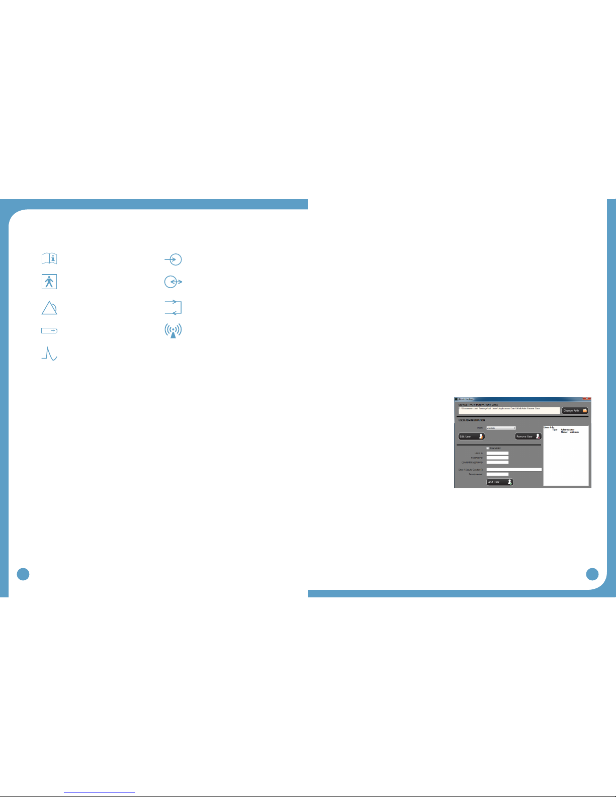
2.8 SymbolsandDenitions
MeaningofSymbols
Attention, consult accompanying
documents
Indicates connector location for
Clinician Heel Sensor and
optional Patient Foot Sensor
Type BF Equipment Indicates input/output connector
location for WalkLink
Indicates Error Signal Indicates exercise button
Indicates battery location and
positioning
Ionizingradiation(Wirelessradio
transmitter/Bluetooth)
Indicates impulse, STIM button
3.0 WalkAnalyst Software
WalkAnalyst is the software used by the clinician to interface with the WalkAide unit. This is
used to collect and analyze the patient’s walking data and program/personalize the WalkAide
tothepatient’sgait.Thegaitanalysisdataaresavedintheprotectedpatientle.The
WalkAnalyst features Rapid+ Program for easy step programming and Standard Program
for advanced programming. It also allows clinicians to evaluate and report on WalkAide
performace compared with the patient wearing a brace or no assisted device. This software
allowsthecliniciantocustomizeclinicalpreferencessuitabletoaspecicpatientpopulation
orhis/herttingprocesses.
3.1 Installation
WalkAnalyst only needs to be installed once in order to run this program. Installation requires
administrator or power user rights.
1.InserttheWalkAnalystCDorashdriveintheappropriatedrive.ThePCmayhavean
external CD or USB Port. Make sure it is properly connected and operating correctly
priortoinsertingtheWalkAnalystCD/ashdrive.IfyoualreadyhaveWalkAnalyst
softwareinstalled,youcangetsoftwareupdatesfromtheWalkAide.comwebsite(look
fortheDownloadlinkavailableontheSupportpage).
2. The installer should automatically start. Follow the set up instructions that will appear.
3.Iftheinstallerdoesnotstartautomatically,ndtheappropriatedriveiconandopenthe
folder.ForWindowsXPdoubleclickontheSetup.exele.ForWindows7,rightclick
on Setup.exe and choose “Run as Administrator”. Follow the set up instructions that will
appear.
4. The WalkAnalyst program will be installed in the Program Files/Innovative Neurotronics
directory unless another directory is selected.
5. Once the program has been installed, an icon will be created on the desktop for quick
access. WalkAnalyst can also be accessed from the Windows start menu. For detailed
instruction,refertoWalkAnalystInstallation&BluetoothCongurationGuideprovided
with the WalkAnalyst Software.
Note: The WalkAnalyst installer will detect if Microsoft .NET framework 3.5 Service Pack 1
(orbetter)isinstalledonyourcomputer.Iftheapproriateframeworkisnotinstalled,theuser
cannditintheWalkAnalystinstallationCD/ashdriveorMicrosoftDownloadCenter.After
frameworkisinstalled,restartWalkAnalystinstallationagain(step3).
3.2 WalkAnalystUpgrades
WalkAnalyst software, when connected to the internet, prompts the user when a new upgrade
isavailable.DownloadthesoftwarefromtheWalkAide.com(Support>Download)siteor
contact the information technology department to download and upgrade the software.
3.3 Administration
If you are a WalkAnalyst user with Administrator level access you can select on the
Administration link to open Administration screen.
User administration:
To add a new user, check/uncheck•
administrator access checkbox, type in
theUserID,password(twice),asecurity
questionspecictotheuser,asecurity
answer and press the Add User button.
The user will use the security answer to
change the password and/or change the
security question/answer.
To edit a user, select a user and•
press the Edit User button. To edit
user information, check/uncheck
administrator access checkbox, edit
UserID,password(twice),asecurityquestionspecictotheuser,andasecurityanswer.
To remove a user, select a user and press the Remove User button.•
Patientlestorageadministration:
The current location for WalkAide patient data is displayed in the Default Path for Patient•
Dataeld.PresstheChangePathbuttontochangethisdefaultpath.
Figure 15: Administration
18
19
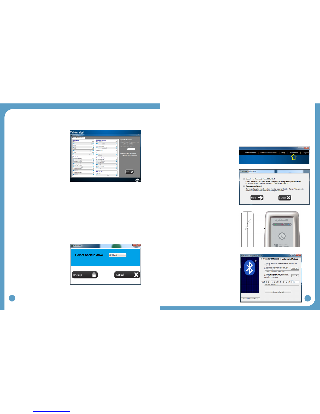
3.4 ChangingClinicalPreferences
WalkAnalyst software allows the clinician to modify default preferences.
Clinical preferences:
The WalkAide unit default preset
values can be changed to individual
preferences. For example, a pediatric
center may decide to set the default
pulse width value to a lower, more
comfortable, level suitable for
pediatric patients.
Report preferences:
WalkAnalyst provides an option to
compare a patient’s gait performance
with the gait of the patient wearing a
brace(suchasAFO)ornoassisted
device. A preset distance suitable to
the clinical setting, as well as distance
measurement unit, can be changed.
Programmingpreferences:
You can change the programming option by checking or unchecking the Hide Heel
Programming checkbox. When checked, WalkAnalyst hides all heel programming or heel data
collection options.
3.5 Backup
The WalkAnalyst software allows you to back up patient data in an external, internal or
network drive. The clinician must have adequate access to save data to the drive.
Steps:
Log on to WalkAnalyst•
Select Backup Patient Data on the•
WalkAnalyst home screen
Select the backup drive and press•
the BACKUP button
Backeduppatientlescan•
belocatedinthe<drive>:\
WalkAideBackupYYYY_
Mon_DDfolder.(example:e:\
WalkAideBackup2012_Nov_11).
4.0 WalkLinkCongurationandBluetoothPairing
4.1 Conguringinitialset-upprocess(Pairing)
A one-time link must be created from the computer to the WalkLink. This is called the “pairing
process”. Following the guidelines below to accomplish this process.
Plug in your USB Bluetooth adapter with•
the computer powered ON.
Start the WalkAnalyst application and log•
on.
Press the Bluetooth link on WalkAnalyst•
homescreen(seeFigure19).
Select‘CongurationWizard’andpress•
the Nextbutton(seeFigure20).
TurnONtheWalkLink:Greenashing•
light on the face of the WalkLink indicates
theunitisON.(seeFigure21)
Reset the WalkLink: Using the tip of a pen•
or pencil, press and hold the unpair button
(seeFigure21)for3to4seconds.Turn
the WalkLink OFF, wait a few seconds
and turn the power back ON.
•Standardmethod will be applicable
with most computers with Microsoft
Bluetoothstackproperlyworking.(See
the troubleshooting section for pairing a
WalkLinkusingthealternatemethod.)
Enter the MAC Address and Connect:•
Read the last 3 digits of the MAC address
from the back of the WalkLink device and
enter them in the appropriate boxes on
theWalkLinkCongurationWizardscreen
(Figure22)andpressthe“Connectto
WalkLink” button. Press the “Connect to
WalkLink” button again if WalkAnalyst fails
tondtheWalkLink.Itmaytakeabouta
minute to establish a connection to the
WalkLink.Whennished,aconrmation
message will appear. Press OK to
completetheinitialconguration.The
WalkLink will show a blinking blue LED.
The blinking green LED and WalkAnalyst
WalkLink indicator will turn blue.
Figure 16: Preferences
Figure 17: Backup
Figure 19: Bluetooth
Figure20:SelectCongurationWizard
Unpair button
Figure 21: WalkLink unpair button
Figure22:CongurationWizard
20
21
Note: IfthecomputerandtheWalkLinkwerepreviouslyconnected: Turn on the
WalkLink and open the WalkAnalyst software program. The blue light on the front of the
WalkLink should begin to blink. The WalkAide can be attached to the WalkLink at any
time. The blue light in the upper left hand corner of the WalkAnalyst screen will indicate a
solid connection to the WalkLink, and the green light will indicate a solid connection to the
WalkAide.
5.0 FittingProcess
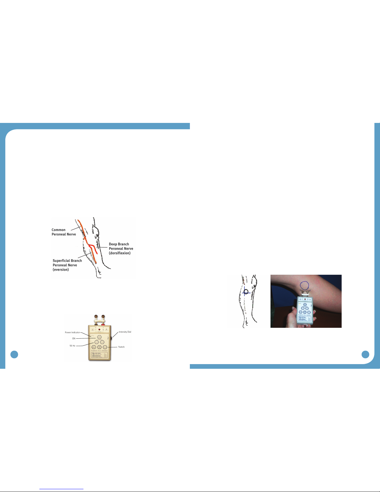
5.1 Pre-screeningwiththePeripheralNerveStimulator
There are two primary purposes of the peripheral nerve stimulator testing procedure. The
rstistodeterminetheviabilityofthecommonperonealnerveandthedegreeofinnervation
oftheperoneuslongus(supercialbranch)andtibialisanterior(deepbranch)muscles.
The second purpose is to identify initial placement of the posterior electrode to produce a
‘balanced’dorsiexionandeversionmovementofthefoot/ankle.(Figure23)
Preparetheperipheralnervestimulatorbypressing:(1)ON,(2)50Hzand(3)Twitch;then
(4)settheintensitydialinbetween0and1.Theorangepowerindicatorlightwillbeseen
toindicatethattheperipheralnervestimulatorison.(Extra9Vbatteriesshouldalwaysbe
available)Theredlightontheperipheralnervestimulatorwillashwhenacircuitbetween
thestimulator,thenerveandthemuscleiscompleted.(Figure24)
1. Always prepare the user for the testing procedure by providing a thorough explanation of
the process and always ask for continuous feedback during the procedure.
2. The user should be comfortably seated in a chair with the affected leg resting on a low
stool.Thelegshouldberelativelyextended,withjustslightkneeexiontosimulatethe
position of the leg at terminal stance during walking, when the stimulation will be initiated.
The heel should be somewhat supported, with the foot close to a neutral alignment.
3.Cleantheskinintheareaaroundtheheadofthebulawithsoapandwaterandwipe
dry. Failure to adequately prepare the skin may cause improper contact and provide less
than ideal stimulation
4.Identify(andmark)theheadofthebula.Thecommonperonealnerverunsposterior
anddistaltotheheadofthebula.(Figure23)
Thesupercialbranchinnervatestheperoneuslongustoproduceeversion.
Thedeepbranchinnervatesthetibialisanteriortoproducedorsiexion(andinversionin
anon-weightbearingcondition).
5.Wettheareaaroundtheheadofthebulagenerouslywithwater.Placeonehandon
the lower leg in a position to be able to feel the contraction of both the peroneus longus
and tibialis anterior muscles.
6.Identifytheintersectionofalinedroppedverticallybehindtheheadofthebularand
horizontallybelowtheheadofthebula.Thisisagoodstartingpointtotestforviability
ofthecommonperonealnerve.(Figure25)
7. Position the peripheral nerve stimulator against the leg so that the black-based silver
node is posterior and the red-based silver node is anterior. Press the peripheral nerve
stimulatorrmlyintotheleg,keepthestimulatorperpendiculartotheleg.Gradually
turn up the intensity dial on the peripheral nerve stimulator until muscle contraction
is evidenced. Most often, this will be contraction of the peroneus longus when the
supercialbranchofthecommonperonealnerveisstimulated.(Figure25)
8.Slideorshifttheperipheralnervestimulatorslightlyanteriorlytondthedeepbranchof
the common peroneal nerve and to produce a contraction of the tibialis anterior muscle.
Watch and feel for any slight twitch of the tibialis anterior muscle. Once the twitch is
discovered, stop sliding the peripheral nerve stimulator and start increasing the intensity
leveluntilamorefunctionaldorsiexionmovementisproduced.
Figure23:Supercialanddeepbranchesofthe
common peroneal nerve
Figure 25: Initial placement of the peripheral nerve stimulator
Figure 24
22
23
9.Balancetheeversionanddorsiexionmovementswithveryslightshiftingofthe
peripheral nerve stimulator. After determining the most appropriate ‘balance’ point, mark
the location of the posterior black-based node on the leg. This is the starting point for
placement of the posterior electrode.
The location of the branching of the common peroneal nerve varies between individuals.
Slow and methodical testing of the area will identify the most appropriate starting point for
placement of the posterior black electrode.
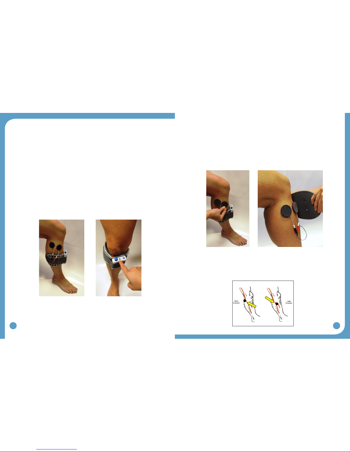
5.2 ElectrodePlacementsandSystemPreparations
1. Turn the WalkAide OFF and attach the electrode lead cable to the back of the WalkAide.
Directthecabletotherighttotarightlegandtothelefttotaleftleg.Thisallows
approriate cable length to attach the electrodes and also prevents excessive bending or
exingoftheelectrodeleadcable.
2.AttachtheWalkAidetothecuffonthemedialattenedarea.Positionthecuffaroundthe
mid-calf region and secure in place below the potential electrode sites. This places the
WalkAide in a convenient location to hook up the electrodes.
3. Moisten the electrode with recommended medium. Place the back electrode over the
markidentiedduringthetestingprocedurewiththeperipheralnervestimulatorandthe
frontelectrodeontheupper1/3ofthetibialisanteriormusclebelly.(Figure26)
4. Connect the electrodes to the WalkAide electrode lead cable. Make sure the BLACK
lead(negative)isconnectedtotheBACKelectrodeandtheREDlead(positive)is
connectedtotheFRONTelectrode.(Figure26)
5. Turn the WalkAide ON by turning the blue Intensity Knob in a clockwise direction to the
1(on)position.Anaudiblebeepwillsoundandagreenlightwillashintermittently
to indicate that the unit is on. ALWAYS start at a low level of intensity and gradually
increase during the testing procedure.
6. While maintaining total contact over the electrodes with one hand, test STIM. This can
beachievedbypressdownonthelargeblueSTIMbuttonontheWalkAide(labeled
√),theHandSwitchontheWalkLink(ifitisconnectedtotheWalkAideandifDefault
Parametershavebeenpreviouslysent),orexercisemodetoinitiatethestimulation.
(Figure27)
7. Once the optimal electrode positions have been found, place Black & Red Markers over
the electrodes. Turn off the WalkAide, release the cuff strap and properly align the cuff
overandaroundthepretibialregion.(Figure28)
TIPS:
Electrode placement determines patient comfort and direction of foot movement.•
Always begin by identifying the starting point for the black electrode•
Generally, shifting the black electrode more posterior and proximal elicits more eversion;•
andshiftingtheblackelectrodemoreanterioranddistalelicitsmoredorsiexion.(Figure
29)
Figure 26: Placement of electrodes, cuff and
WalkAide for initial testing
Figure 27: Exercise mode button
Figure 28: Carefully align the cuff over the electrodes and secure the leg
Figure 29: In general, the posterior black electrode
determines the direction of the foot lift

24
25
Anatomical variations are common.•
Adjust the spacing between the black and red electrodes to achieve the desired function•
and contraction of muscle.
Ifthecontractionisnotoptimalinitially,considerusingtheExerciseModepriortonal•
placement of the electrodes to “wake up” the neural pathways.
Makesmallmovementswhenshiftingtheelectrodestodeterminenalelectrode•
placements in order to detect subtle changes in muscle contraction/function.
Leavetheelectrodesontheskinuntilnalplacementisidentiedtopreventdissipationof•
the water and to maximize user comfort. If the electrodes lose contact with the skin, rewet
and reapply.
Evaluate functional foot movement during sitting and standing before asking the person•
to walk, assuring a safe and effective foot lift for safe walking. Function can differ with
changes in patient position due to movement of the peroneal nerve.
PreparationforDataCollection:
Open WalkAnalyst and log on.•
CompletetheWalkLinkandBluetoothpairingprocess(section4).•
Connect WalkLink and WalkAide control unit using a WalkLink•
cable(Figure31).
A blue light for WalkLink and green light for WalkAide on•
WalkAnalyst software indicate the system is ready for data
collection.
5.3 FittingaNewPatient
Select CreatePatientProle.Addbasicinformation(patientID,location,primarydiagnosis,
etc)andsavethepatientle.SelectProgram.
Duringtheinitialtting,youhavethe
following programming options:
Rapid+Program•is a simple and easy
programming option that can be used by
all clinicians. See section 5.5.1 for all the
details of Rapid+ Programming.
•StandardProgram is a comprehensive
programming option used by advanced
clinicians. See section 5.5.2 for all the
details of Standard Programming.
•RecoverProgram is used when
the clinician attends a patient with a
programmed WalkAide unit but is missing
thepatientle.Seesection5.5.3formore
details.
5.4 FittingaReturningPatient
Select OpenPatientProle and select one
of the following options:
Re-Program:•to re-program the patient
using Rapid+Program(seesection
5.5.1)orStandardProgram(seesection
5.5.2)option.
Adjustment:•to make adjustment to the
WalkAideprogram.(seesection5.5.3)
•TransferProgram: to re-program a
WalkAide with a preferred setting or copy
a WalkAide program from one unit to
another.(seesection5.5.4)
•Evaluation & Report: to conduct a
comparative evaluation of the WalkAide.
(seesection6)
Figure 30: Final placement of electrodes relates to individual anatomical requirements
Figure 31: WalkLink cable
connects WalkLink and WalkAide
during data collection
Figure32:Createpatientprole
Figure 33: New patient programming options
Figure34:Openpatientprole
Figure 35: Returning patient programming options
26
27
5.5 ProgrammingOptions
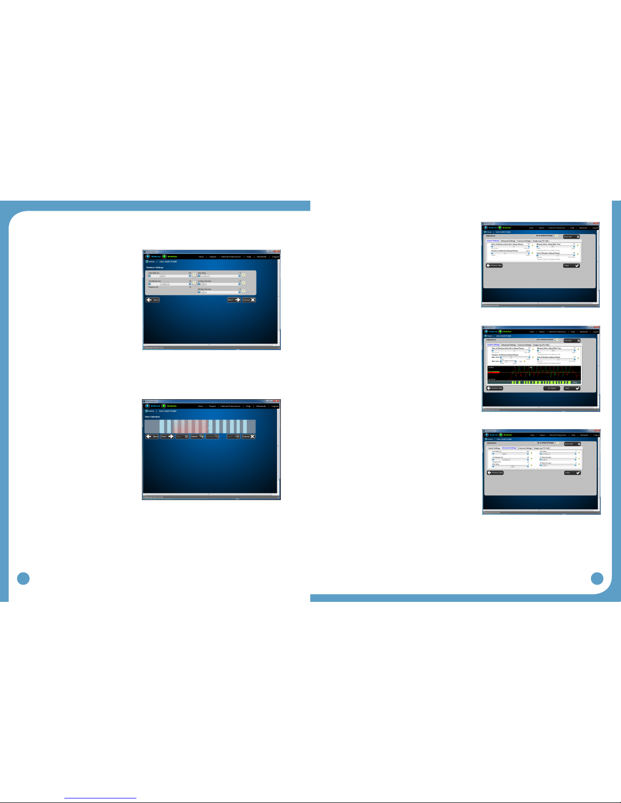
5.5.1 Rapid+Program
Step 1:
Select the Rapid+ Program button to
initiate programming and initialize the
WalkAide device to operate by hand
stimulation from the WalkLink.
Rapid+ Program interface allows
you to change stimulus settings
such as Pulse Width, Time Between/
Frequency, Extra Stimuli, On Ramp
TimeandOffRampTime.(Setthe
WalkAide unit to generate Beeps
duringstimulation.)PresstheNext
button.
TIPS:
Hoveroverthe‘?’button,nexttotheelds,fordenitionsofhowthesestimulussettingsaffect
the patient’s walking
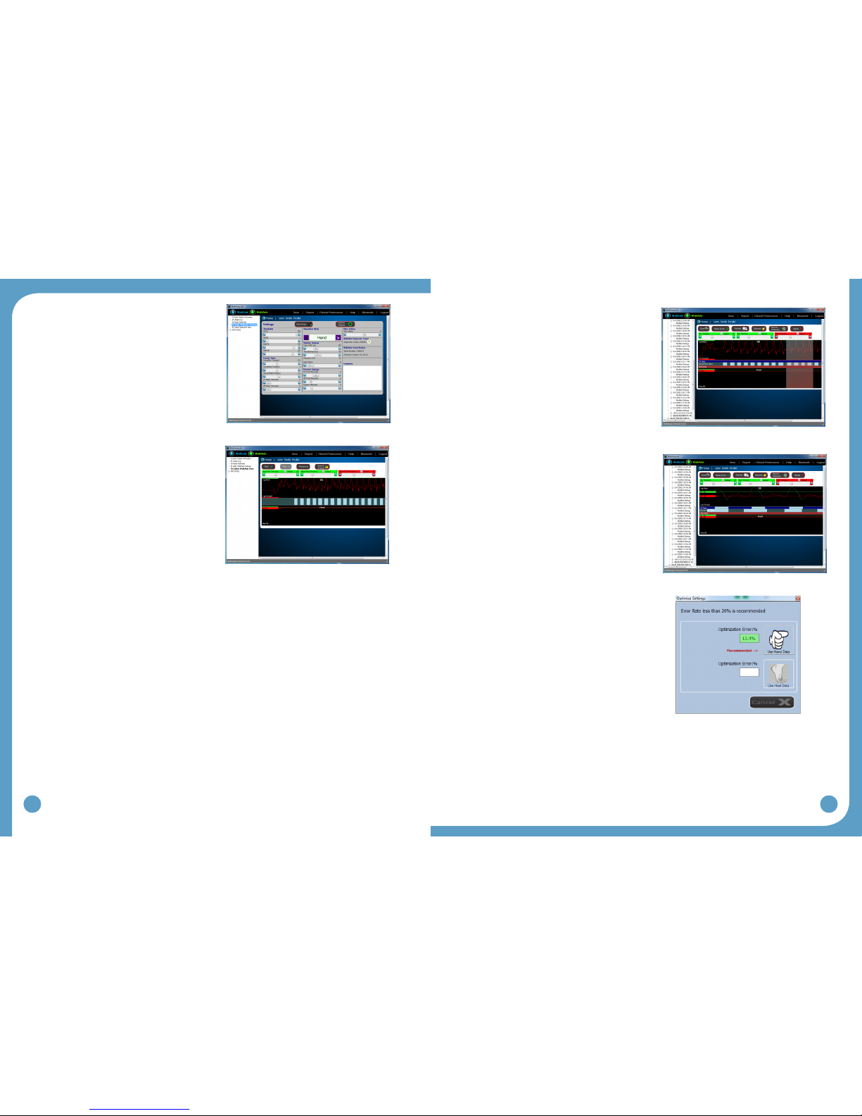
Step 2:
Select Start to begin collecting walking
data. Walk shoulder to shoulder by the
patient’s side and synchronize hand
stimulation from the WalkLink with the
patient’s strides of the leg wearing
the WalkAide. Select “Stop” upon
completion of data collection.
Highlight the desired portion of the
collected data by left clicking and
dragging the mouse arrow. Upon
releasing the mouse, the WalkAide
settings are calculated and an
optimizationerrorisdisplayed.(An
optimization error of less than 20% is
recommended).PresstheNext button to program the WalkAide unit in the Tilt stimulation
mode and initiate adjusting the WalkAide on the Adjustment screen.
Step 3:
ActivateBeeponStim mode. Observe as the
patient walks with the newly programmed settings.
Adjust the control settings based on clinical
observation and patient feedback.
ShowGait: Click on “Show Gait” to observe
patient’s gait and make adjustments to control
settings(Figure39).Youcanchangecontrol
settings on the live gait display screen or from the
controls on screen. You can also freeze the display
and make adjustments to the control settings.
AdvanceSettings: Click on the Advance Settings
tab to adjust the Comfort or Quality characteristics of
thestimulation.(Figure40)
Figure36:(Rapid+)Stimulussettingsadjustmentpriortodatacollection
Figure37:(Rapid+)Highlightcollecteddata
Figure38:(Adjustment)Controlsettings
Figure39:(Adjustment)Showgait
Figure40:(Adjustment)Advancesettings
28
29
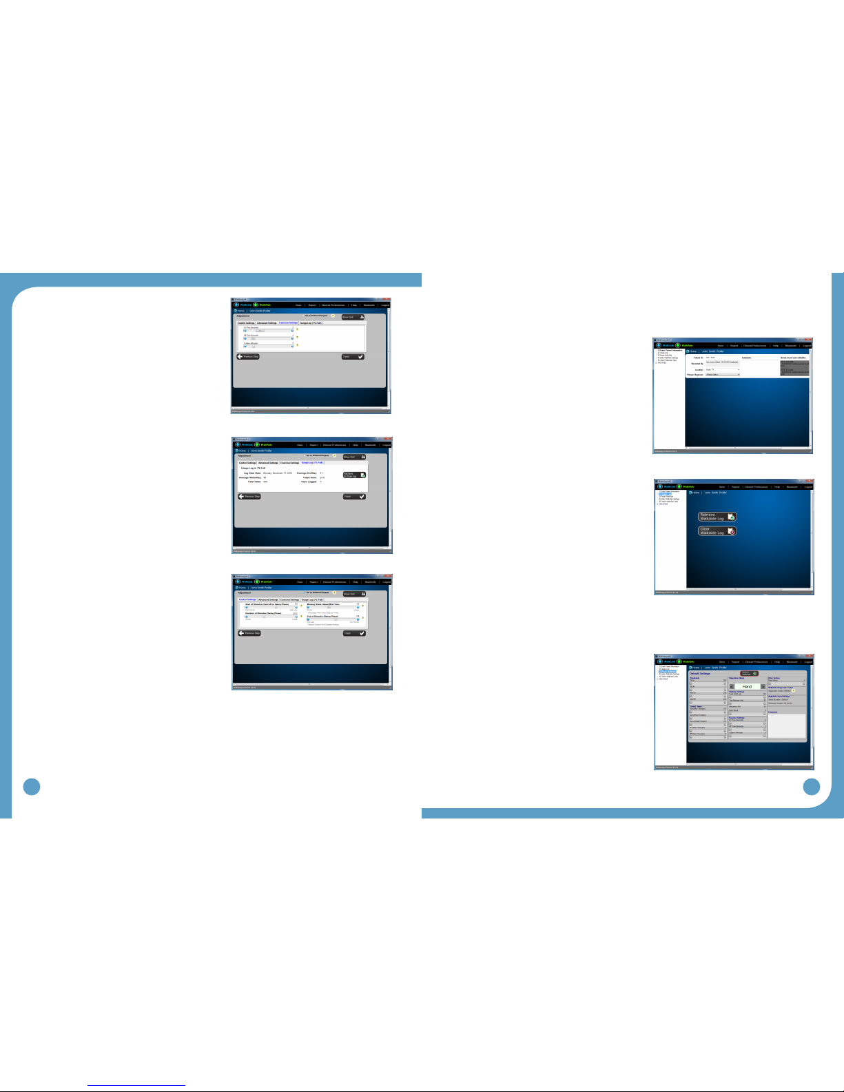
ExerciseSettings: Click on the Exercise Settings
tabitoadjustpatient’sexercisesettings.(Figure
41)
UsageLogs: Click on the Usage Logs tab to view
and/orclearusagedata.(Figure42)
PreferredSetting: You can use the checkbox
“Set as Preferred Setting” to tag a setting as a
preferredsetting.(Figure43)
SelectFinishtonalizedtheRapid+program.
5.5.2 StandardProgram
SelectStandardProgram(Figure33)toinitiateStandardProgramming.
Step 1:
Enter Patient Information
Step 2:
Clear Usage Logs
The WalkAide collects usage data and gait•
activity for 69 days since the log start date. The
log includes log start date, hours per day and
number of stims per day. [The usage log will
not record hours of usage or number of stims that
occur in exercise mode.]
For a New Patient Kit: Select Clear Usage Log to•
set the internal date/time stamp and start a new
69-day tracking sequence.
For an existing user: Select Retrieve Usage Log•
to download the most recent walking activity data.
This Usage Log will be saved with a date and timestamped entry under Collected Logs.
If the usage log is almost full, usage log should be cleared to set a new 69-day tracking
sequence.
Step 3:
Reset WalkAide
Default settings provide basic reference•
information to the software and set the stimulation
mode to “hand” to activate the hand switch
button on the WalkLink. These settings allow the
clinician to initiate the swing and stance duration
for the best walking data collection. These
settings cannot be altered on this page.
Click on “Send to WalkAide” to send the default•
settings and reset the WalkAide.
Figure41:(Adjustment)Exercisesettings
Figure42:(Adjustment)Usagelogs
Figure43:(Adjustment)Preferredsetting
Figure44:(Standard)Patientinformation
Figure45:(Standard)Usagelogs
Figure46:(Standard)ResetWalkAide
30
31
Step 4:
VerifyWalkAideSettings
This screen captures the current WalkAide•
settings. Setting adjustments can be made
toaccommodatespecicclinicalneedsof
apatient.(i.e,Reducepulsedurationfora
sensitive patient; or modify Exercise Settings
topre-settheexerciseprogram).
Settings are sent to WalkAide as soon as they•
are changed on the screen.
Step 5:
Collect WalkAide Data
Prepare patient to walk. Assure the cuff and•
WalkAide are properly positioned and there
are no dangling cables that might impede
walking.
Select Start. This collects real-time data•
which appears on screen. Stand shoulder
to shoulder on the same side of the patient’s
affected limb, provide support assistance as
needed. Prompt the patient to begin walking
with their sound side.
ActivatedorsiexionbypushingtheWalkLink•
stim button from heel off through heel strike.
Step 6:
Select Stop.
Step 7:
Select Save and Analyze.
ProcesstheData
Dataprocessinginvolvesfollowingthesequenceoficons[fromlefttoright)displayed•
abovetheTiltdatagraph.’Zoom’,‘Autoset’and‘Optimize’aretherstthreestepsinvolved
in processing the walking trial.
1.‘Zoom’-Pressandholdtheleftmousebutton
and then drag the cursor to select the desired
steps. This ‘Selection’ process will highlight
selected steps to create the most effective
walking program.
2.‘Autoset’-automaticallymodiesthesettings
based on statistically calculated values from
the walking data. Click ‘OK’ to accept the
statistical calculations and standard deviation.
3. ‘Optimize’ - optimizes the calculated statistical
settings in reference to Hand or Heel
stimulations and calculates error rates. An
error rate of less than 20% is recommended.
Select the preferred reference signal and
associated error by clicking either the Use
HandDataorUseHeelData.(Figure51)
Figure47:(Standard)VerifyWalkAidesettings
Figure48:(Standard)Collectwalkingdata
Figure49:(Standard)Select(zoom)walkingdata
Figure50:(Standard)Autosetoperationcompleted
Figure51:(Standard)Optimizeoperationcompleted
32
33
TIPS:
If the error rates are greater than 20%:•
1. ResetZoomtoseeallDataandselectadifferentsequenceofstepsfor
Optimization, or
2. Collectanewwalkingtrialfordataprocessing.RepeattheZoom,Autosetand
Optimize procedure.
The WalkAide unit is now programmed for the individual.
TIPS:
CollectanalwalkingtrialinTiltModetoverifyeffectiveandefcientprogrammingofthe
WalkAide. Click CollectWalkingData and repeat the data collection procedure for a walking
trialwiththeWalkAideinTiltMode(clickonCollectWalkingData,StopCollectingWalking
Data,SaveandAnalyzethisWalkingData).
Thenalwalkingtrialshouldrevealaneffectivepatternofstimulationandproduceasafe
and symmetrical pattern of walking. Discuss the wearing schedule and care of the WalkAide
unit. If any missing stimulations were noted, then make manual adjustments to the walking
programasneeded.(referto8.2ManualAdjustmentoftheStimulationSettings.)
5.5.3 Adjustment
SettingadjustmentsaretransferredtotheWalkAideinstantaneouslyandareconrmedby
audible beeps. Activate WalkAide’s “Beep on Stim” mode. Select “Show Gait” button to
display patient’s gait graphically.
ShowGait: Click on “Show Gait” to observe patient’s gait and make adjustments to control
settings(Figure39).Youcanchangecontrolsettingsonthelivegaitdisplayscreenorfrom
the controls on screen. You can also freeze the display and make adjustments to the control
settings.
AdvanceSettings: Select the “Advance Settings” tab to adjust the comfort or quality
characteristicsofthestimulation.(Figure40)
ExerciseSettings: Select “Exercise Settings” tab to adjust the patient’s exercise settings.
(Figure41)
UsageLogs: Select“UsageLogs”tabtoviewand/orclearusagedata.(Figure42)
PreferredSetting: You can use the checkbox “Set as Preferred Setting” to tag a setting as
preferredsetting.(Figure43)
Select FinishtonalizetheAdjustment.
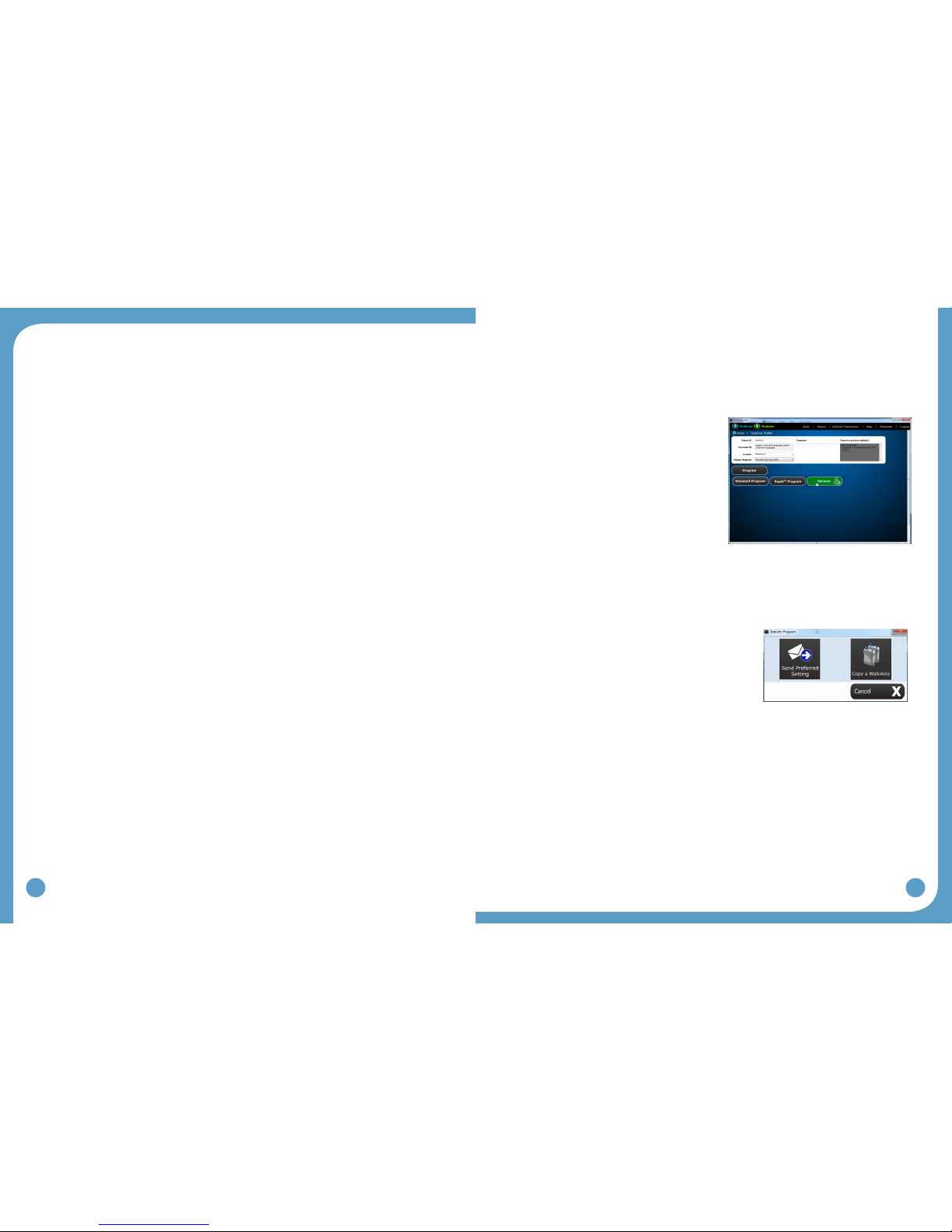
5.5.4 RecoverProgram
Select Recoverifyounoticethatapatientleismissingforapreviouslyprogammed
WalkAide unit. A patient may also see a clinician at a clinic for a follow-up visit which is
differentfromtheonewherethepatientwasoriginallytted.
Connect the WalkAide to a paired WalkLink.•
Select•CreatePatientProle, enter the
patient’sbasicinformation(patientID,location,
primarydiagnosis,etc.),andsave.
Select•Program, and choose Recover.
Anewpatientproleiscreatedandsavedas
WalkAnalyst recovers the patient WalkAide
settings. After recovery, WalkAnalyst enables
access to all programming, adjustment, reporting
options suitable for returning patients.
5.5.5 TransferProgram
Transfer a preferred setting to the WalkAide or transfer the settings from one WalkAide to a
different WalkAide.
SendPreferredSetting:
Tag an already programmed WalkAide setting as preferred
program from Rapid+ or Standard programming interface.
Select SendPreferredSetting, you can quickly send
this preferred setting to WalkAide. If no preferred setting
is tagged as preferred setting, WalkAnalyst sends the
very last programmed setting to WalkAide. The WalkAide
adjustment window is displayed to make further WalkAide
adjustment.(Thisfeatureisusefulinarehabenvironment
whenaWalkAideisusedformultiplepatients.)
Copy a WalkAide:
WalkAnalyst allows you to copy WalkAide settings from one WalkAide to another. After the
WalkAide setting is copied to a different WalkAide unit, the adjustment window is displayed to
make further WalkAide adjustments.
Figure 52: Recover program
Figure 53: Transfer program

34
35
5.6 ExerciseModeSettings
WalkAide can be used as a therapeutic modality, as an adjunct to therapy or as a way to
condition the user’s nerve or muscle. It is intended to be used only while the user is seated.
ChangetheExercisesettingsfromtheVerifyWalkAidesettingsscreenoftheStandard
Program(Figure47)orExerciseSettingstaboftheRapid+orAdjustmentscreen(Figure41).
The Exercise settings ranges are as follows:
On Time: 1 - 5 seconds
Off Time: 1 - 10 seconds
Exercise Duration: 1 - 30 minutes
SampleExerciseSettings
User with Severe
Atrophy(1:5)
User with Moderate
Atrophy(1:3)
User with Minimal to
NoAtrophy(1:2)
OnTime(Seconds) 1-2 1-3 1-5
OffTime(Seconds) 5-10 3-10 2-10
Duration(Minutes) 5-10;
gradually increase
15;
gradually increase
15-30
Number of sessions
per day
Start with 1;
gradually increase
Start with 1;
gradually increase
1-2
Figure 54: Sample exercise settings
TIPS:
TheExerciseModemaybehelpfulduringttingtoverifycorrectelectrodeplacement.•
SomeusersmaybenetfromusingtheExerciseModeto“warmup”theneuralpathways•
prior to walking.
Always have the patient actively engaged in the treatment session.•
Activate exercise mode by pressing and holding down the middle button until the WalkAide
beeps. Discontinue the Exercise Mode by simply turning the WalkAide unit off, and turning
the WalkAide unit on again. The WalkAide control unit returns to Walking mode. Always turn
the WalkAide unit off and then on again after any exercise session.
5.7 WearingSchedule
Gradual introduction into wearing of the WalkAide system is important. The Wearing
Schedulebelowservesasageneralguidelineandcanbemodiedbythecliniciantomeet
thespecicneedsoftheindividual.Usersshouldproceedthroughthedailywearingschedule
andincreasewearingtimeonlyifnoskinirritationand/ormusclesorenessispresent.(Figure
55)
ON Time OFF Time
Days 1-3 15-60 minutes 30 minutes
Days 4-6 1-3 hours 30 minutes
Days 7-9 3-5 hours 30 minutes
Days 10-12 5-6 hours 1 hour
Days 13-14 6-8 hours 1 hour
Figure 55: Wearing schedule
TIPS:
If muscle soreness occurs, reduce the wearing time or discontinue use and contact your•
WalkAide clinician.
If skin irritation or redness occurs under the electrodes, do not resume WalkAide•
stimulation until the redness disappears. If the redness has not disappeared by the end
of the scheduled off period, do not reapply the WalkAide until the redness disappears and
report this occurrence to your WalkAide clinician.
Slowly work in to full-time wearing of the WalkAide System. How well the user tolerates•
the WalkAide during this break-in period will depend on each individual’s daily regimen and
overall activity level.
Remove the cuff at regular intervals throughout the day and inspect the skin under the•
electrodes.Theseareasmaybepinkduetoincreasedbloodowundertheelectrodes,but
this redness should disappear quickly. If the redness persists, discontinue WalkAide wear
until the redness completely disappears.
DO NOT use moisturizing soaps, lotions or oils to soften the skin. Make sure the skin is•
clean and dry prior to applying the cuff.
Make sure the WalkAide is applied correctly with appropriate electrode position each time•
to maximize function and minimize any potential discomfort.
If shaving the leg is desired, this should be done in the evening after the WalkAide has•
been removed for the day to prevent potential irritation during daily wear.
Wet the electrodes with recommended medium before applying the cuff. Rewet the•
electrodes occasionally throughout the course of the day to assure good conduction and
maximize conductivity.

36
37
Precautions for WalkAide wear:
Skin irritation under the electrodes can occur in a small percentage of FES users. Common•
causes of irritation are use of lotions or perfumed soaps, recent shaving, non-compliance
with break-in schedule, failure to properly wet electrodes, poor electrode placement that
forces an excessively high intensity level, and failure to change the electrodes often
enough. The best way to avoid skin irritation is to increase to all day wear slowly, maintain
proper skin hygiene, practice proper electrode care and choose the placement that allows
for the least amount of stimulus intensity. Once irritation has occurred, the WalkAide must
be discontinued until the skin is 100% clear of irritation. Using the WalkAide over irritated
skin will only exacerbate the condition.
5.8 UsageLog
RetrieveUsageLog–AccessibleinStandardProgram(Figure45)ortheUsageLogs•
tabontheAdjustmentscreen(Figure42).UsagedataduringWalkAideExerciseMode
operation are not part of the usage logs.
Collected logs section of the Standard Program archives displays all captured usage logs•
labeled with the capture date.
The WalkAide unit collects usage data for up to 69 days since the last usage data reset•
date and for the current date. To reset the WalkAide unit Usage log, click on the Clear
Usage Log button from the Standard Program interface and Retrieve and Clear Usage logs
button on the Adjustment screen.
Graphicalview(Totalhours/day,#ofStims/day)•
Tabularview(Totalhours/day,#ofStims/day)•
Reports – Select ‘Print’ icon in the upper right corner of the screen. Select any of the•
walking trials to print a report showing the data analysis screen and associated parameters.
6.0 Evaluation&Reporting
WalkAnalyst provides an option to compare a patient’s gait performance with WalkAide versus
wearing a brace and no assisted device. During this evaluation process, it’s critical that you
collect walking data for these different conditions for a preset distance. Select the evaluation
data and generate comparative reports to highlight the WalkAide performance improvement
and justify medical necessity of WalkAide.
Evaluation options:
CollectWalkingData-NoDevice:
When collecting walking data with no assisted device, attach the WalkAide on a cuff and wrap
the cuff below patient’s knee. The WalkAide device should be turned ON and connected to
WalkLink. Disconnect the electrode lead cable from the back of the WalkAide. Select No
Device to launch the data collection window. Press the Start button and ask the patient to
start walking. The patient’s gait is graphically displayed on the screen. Monitor the start and
end points of the preset distance the patient walks. Press Stop to end data collection. Use
a mouse to select a graphical section of the patient’s gait, between the start and end points
of the preset distance. When prompted, enter the evaluation distance and number of strides
taken to travel this distance. Press the Save button to save this evaluation data.
CollectWalkingDataWithBrace:
When collecting walking data for a Brace, attach the WalkAide on a cuff and wrap the
cuff below patient’s knee. The WalkAide device should be turned ON and connected to a
WalkLink. Disconnect the electrode lead cable from the back of the WalkAide. Select With
Brace to launch the data collection window. Press the Start button and ask the patient to
start walking. The patient’s gait is graphically displayed on screen. Monitor the start and
end points of the preset distance the patient walks. Press Stop to end data collection. Use
a mouse to select a graphical section of the patient’s gait, between the start and end points
of the preset distance. When Prompted, enter the evaluation distance and number of strides
taken to travel this distance. Press the Save button to save this evaluation data.
CollectWalkingDataWithWalkAide:
When collecting walking data with the WalkAide, complete the WalkAide programming
to operate in the TILT mode. WalkAide device should be turned ON and connected to a
WalkLink. Electrode leads should be properly placed and connected to WalkAide. Select
WithWalkAide to launch the data collection window. Press the Start button and ask the
patient to start walking. Patient gait is graphically displayed on the screen. Monitor the start
Figure 56: WalkAide evaluation and reporting
Table of contents
Popular Medical Equipment manuals by other brands


Getinge
Getinge Arjohuntleigh Nimbus 3 Professional Instructions for use

Mettler Electronics
Mettler Electronics Sonicator 730 Maintenance manual

Pressalit Care
Pressalit Care R1100 Mounting instruction

Denas MS
Denas MS DENAS-T operating manual

bort medical
bort medical ActiveColor quick guide

AccuVein
AccuVein AV400 user manual


