Innovative EBB & FLOW User manual
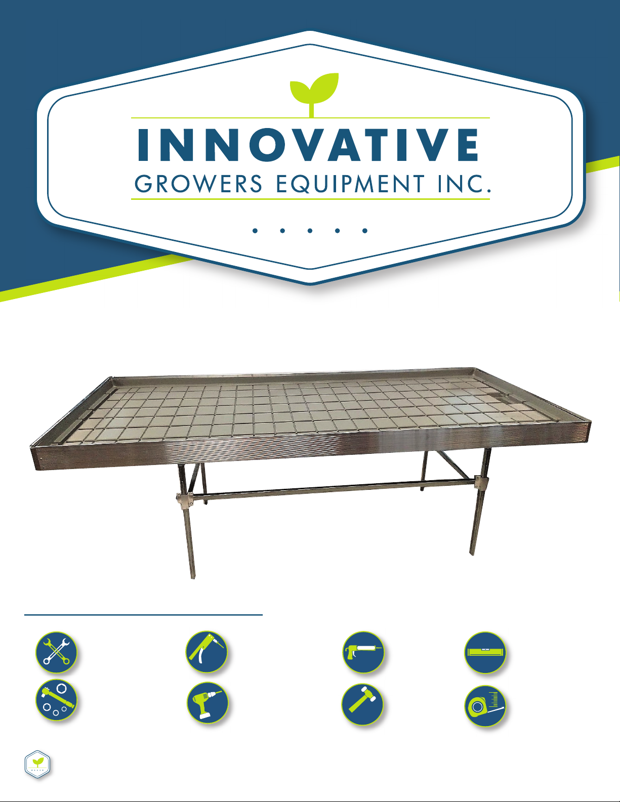
EBB & FLOW BENCH ASSEMBLY INSTRUCTIONS
Complete InstrucƟonal Guide
INNOVATIVEGROWERSEQUIPMENT.COM
Call 815-991-5010 or email us at sales@innovaƟvegrowersequipment.com if you have any quesƟons
7/16” WRENCH
7/16” SOCKET
LEVEL
POP RIVET TOOL
TAPE MEASURE
WE RECOMMEND AN IMPACT
GUN FOR LARGER JOBS
POWER DRILL
ΈFOR BENCHES LARGER THAN 5’Ή
WE RECOMMEND A
PNEUMATIC RIVETER FOR
LARGER QUANTITIES
MALLET
CAULK GUN
TOOLS NEEDED FOR ASSEMBLY
Level
Mallet
Pop
Riveter Caulk Gun
EBB & FLOW BENCH ASSEMBLY INSTRUCTIONS
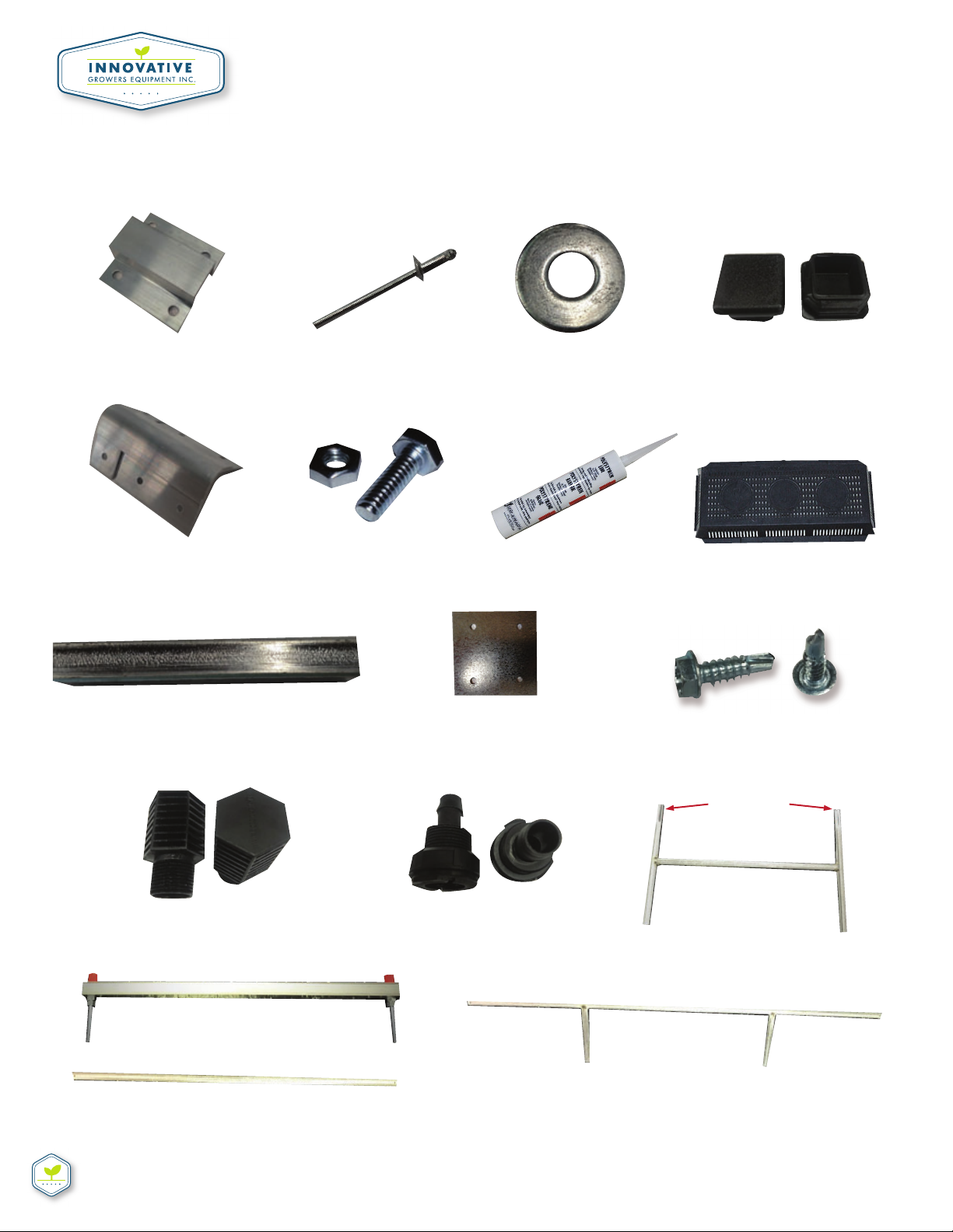
PARTS LIST
INNOVATIVEGROWERSEQUIPMENT.COM
Call 815-991-5010 or email us at sales@innovaƟvegrowersequipment.com if you have any quesƟons
CONFIRM ALL PARTS ARE PRESENT BEFORE STARTING INSTALLATION
ΈA1Ή
SQUARE TO SQUARE CLAMP
ΈA5Ή
BENCH CORNER
ΈA9Ή
STRINGER PIPE INSERT
ΈONLY USE ON BENCHES OVER 27 FTΉ
ΈA12Ή
SCREEN FOR BULKHEAD FITTING
ΈB2Ή
HEADER
ΈE1Ή
END FRAME
ΈONLY USE ON BENCHES OVER 5 FTΉ
ΈB3Ή
BENCH CROSSBAR
ΈA13Ή
3/4 BULKHEAD FITTING
ΈB1Ή
LEGS ΈLEG SUPPORTSΉ
ΈA10Ή
SIDE RAIL JOINER PLATE
ΈONLY USE ON BENCHES OVER 24 FTΉ
ΈA6Ή
1/4 ͳ20 BOLT & NUT
ΈA7Ή
BENCH GLUE
ΈA8Ή
BENCH FILTER
ΈA2Ή
POP RIVET
ΈA3Ή
FLAT WASHER
ΈA4Ή
LOAD BEARINGPLUG
ΈA11Ή
TEK ΈSELFͳTAPPINGΉSCREWS
CRIMPED ENDS
SHOULD BE FACING UP WHEN
YOU BEGIN ATTACHING
SQUARE TO SQUARE CLAMPS
EBB & FLOW BENCH ASSEMBLY INSTRUCTIONS
INNOVATIVEGROWERSEQUIPMENT.COM
Call 815-991-5010 or email us at sales@innovaƟvegrowersequipment.com if you have any quesƟons
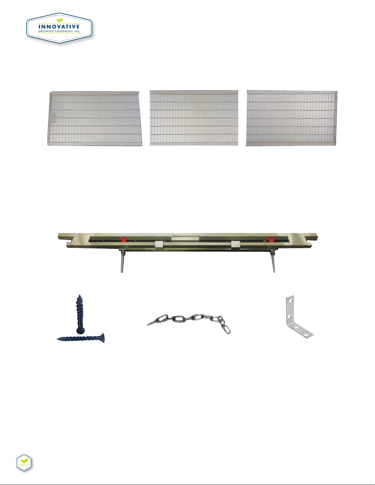
BENCH TRAYS
PARTS INCLUDED WITH MAX ROLL TABLES
CONFIRM ALL PARTS ARE PRESENT BEFORE STARTING INSTALLATION
TRAY GLUE IS USED TO SEAL TRAYS TOGETHER ΈA7Ή
ΈS1Ή
ANITͳTIP / MAX ROLL HEADER
ΈS2Ή
TAP CON SCREWS
ΈS3Ή
SAFETY CHAINS
ΈS4Ή
LͳBRACKET
END TRAY
ΈWITH DRAIN MOLDINGΉ
END TRAYMIDDLE TRAY
FOR LONGER BENCHESΉ

EBB & FLOW BENCH ASSEMBLY INSTRUCTIONS
STEP #1
Lay out the stringer pipe and leg support pieces (B1) on the ground as shown in
the picture below.
STEP #2
Stand up one of the leg supports (B1) on end
(ridged end up as shown in Figure 1) and rest the
end of the stringer pipe on the bar connecƟng
the two leg ends. Please go to InnovaƟve
Growers Equipment youtube page if you need
further instrucƟons on this.
INNOVATIVEGROWERSEQUIPMENT.COM
Call 815-991-5010 or email us at sales@innovaƟvegrowersequipment.com if you have any quesƟons
FOLLOW INSTRUCTIONS BELOW ΈCONT.Ή
FIGUIRE 1

EBB & FLOW BENCH ASSEMBLY INSTRUCTIONS
STEP #3
Take two clamps (A1) and line them up
perpendicular to one another
(outside one verƟcally and inside one horizontal).
***When lined up place the screws (A6) through the
holes facing inward and screw in the nuts (A6) from
the inner porƟon of the frame as shown in Figure 2
STEP #4
Perform the same steps on the other end of the leg support shown. You’ll now have one
end of the bench standing as shown below on Figure 3
Inside Clamp
PosiƟon
Outside Clamp
PosiƟon
INNOVATIVEGROWERSEQUIPMENT.COM
Call 815-991-5010 or email us at sales@innovaƟvegrowersequipment.com if you have any quesƟons
FOLLOW INSTRUCTIONS BELOW ΈCONT.Ή
FIGUIRE 2
FIGUIRE 3
EBB & FLOW BENCH ASSEMBLY INSTRUCTIONS
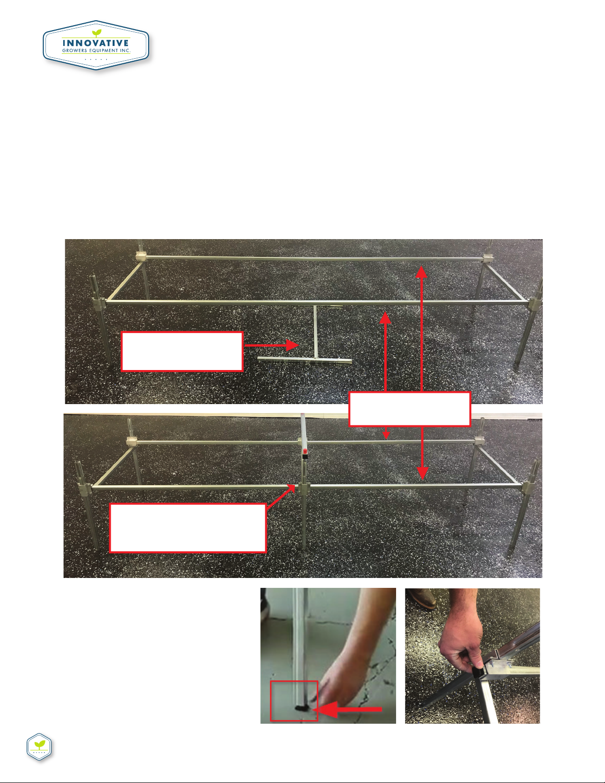
STEP #5
Now stand up the leg support on the opposite end of the frame and aƩach the clamps on
each corner on that side as well. Then stand up any leg supports in the middle of the
frame and repeat the steps again unƟl the frame is complete (shown on Figure 4a & 4b).
NOTE: Longer tables will require addiƟonal leg supports in the middle of the frame so just use the
diagrams aƩached for reference. They will provide spacing requirements
STEP #6
Once the legs are all standing, you
can insert the load bearing plugs
(A4) into the boƩom of all the
welded legs. (B1 – see Figure 5).
Also, install them to the ends of the
stringer pipes on each corner of the
frame (shown on Figure 6).
INNOVATIVEGROWERSEQUIPMENT.COM
Call 815-991-5010 or email us at sales@innovaƟvegrowersequipment.com if you have any quesƟons
FOLLOW INSTRUCTIONS BELOW ΈCONT.Ή
FIGUIRE 4a
FIGUIRE 4b
STRINGER PIPE
UNATTACHED
LEG SUPPORT
ATTACH ALL REMAINING
LEG SUPPORTS TO THE
FRAME
FIGUIRE 5
FIGUIRE 6
INSTRUCTIONS FOR INNOVATIVE ARCHIVAL ROLLING BENCHES
INNOVATIVEGROWERSEQUIPMENT.COM
Call 815-991-5010 or email us at sales@innovaƟvegrowersequipment.com if you have any quesƟons
FOLLOW INSTRUCTIONS BELOW ΈCONT.Ή
STEP #7
Insert the flat washers (A3) in the bolts of the
pre-assembled headers (B2) and slide the bolts
through the opening of the crimped end of the
leg supports (B1 – shown on Figure 7).
STEP #8
***FOR MAX ROLL TABLES ONLY - If you have a max roll table, insert your max roll head-
ers (S1) into legs (B1) like you would regular headers (Figure 8). The locaƟon for these
headers will be labeled on your aluminum side rails as well as your custom bench diagram
FIGUIRE 7
FLAT WASHERS INSERTED HERE
FIGUIRE 8

INNOVATIVEGROWERSEQUIPMENT.COM
Call 815-991-5010 or email us at sales@innovaƟvegrowersequipment.com if you have any quesƟons
EBB & FLOW BENCH ASSEMBLY INSTRUCTIONS
FOLLOW INSTRUCTIONS BELOW ΈCONT.Ή
STEP #9
***FOR MAX ROLL TABLES ONLY - Now, take the rolling pipe and slide them through the
opening of the swinging bar aƩached to the anƟ-Ɵp (S1) on one end of the table and
push it through the opening at the other end of the table (see Figures 9, 10, 11)
Note: if the bench is over 24’ you
will have swedged pipe to connect
to addiƟonal rolling pipe).
FIGUIRE 9
FIGUIRE 10
FIGUIRE 11

INNOVATIVEGROWERSEQUIPMENT.COM
Call 815-991-5010 or email us at sales@innovaƟvegrowersequipment.com if you have any quesƟons
EBB & FLOW BENCH ASSEMBLY INSTRUCTIONS
FOLLOW INSTRUCTIONS BELOW ΈCONT.Ή
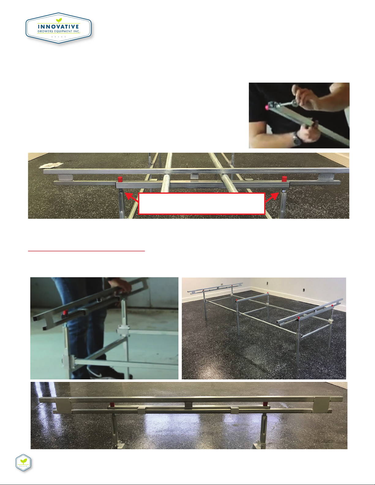
STEP #10
Next, take the end frames (E1) and lay
them across the rolling pipe on each of
the table (Figure 12a and Figure 12b )
STEP #11
Lay out the bench cross bars (B3) over the rolling pipe equally spaced across the bench as
shown in Figures 13a, 13b
Be sure the pre-punched holes are FACING UP when they’re laid across the bench.
FIGUIRE 12a FIGUIRE 12b
FIGUIRE 13a
FIGUIRE 13b

INNOVATIVEGROWERSEQUIPMENT.COM
Call 815-991-5010 or email us at sales@innovaƟvegrowersequipment.com if you have any quesƟons
EBB & FLOW BENCH ASSEMBLY INSTRUCTIONS
FOLLOW INSTRUCTIONS BELOW ΈCONT.Ή
STEP #12
Bench corners (A5) should now be riveted to the END aluminum pieces using the pop
rivets (A2). Figure 14a shows one of the bench corners before its connected to the
aluminum end piece with the pop rivets in the holes. Figure 14b shows what the rivets
should look like aŌer they’ve been riveted. Figure 14c shows what both end aluminum
rails should look like aŌer all the bench corners have been riveted to them. Figure 14d
shows the bench rails and corners connected.
NoƟce the bench corners are now connected to the aluminum
FIGUIRE 14b FIGUIRE 14d
FIGUIRE 14a
FIGUIRE 14c
Table of contents
Other Innovative Lawn And Garden Equipment manuals

Popular Lawn And Garden Equipment manuals by other brands

Vertex
Vertex 1/3 HP Maintenance instructions

GHE
GHE AeroFlo 80 manual

Millcreek
Millcreek 406 Operator's manual

Land Pride
Land Pride Post Hole Diggers HD25 Operator's manual

Yazoo/Kees
Yazoo/Kees Z9 Commercial Collection System Z9A Operator's & parts manual

Premier designs
Premier designs WindGarden 26829 Assembly instructions


AQUA FLOW
AQUA FLOW PNRAD instructions

Tru-Turf
Tru-Turf RB48-11A Golf Green Roller Original instruction manual

BIOGROD
BIOGROD 730710 user manual

Land Pride
Land Pride RCF2784 Operator's manual

Makita
Makita UM110D instruction manual

BOERBOEL
BOERBOEL Standard Floating Bar Gravity Latch installation instructions