Innovative THEPROTECTOR C-1 User manual

MASTER ENVIRONMENTAL
CONTROL C-1
MASTER ENVIRONMENTAL
CONTROL C-1
Instruction Manual

Contents
I. Overview of MASTER ENVIRONMENTAL CONTROL C-1
II. Specifications of MASTER ENVIRONMENTAL CONTROL C-1
III. Warnings & Cautions
IV. Installation Instructions
V. Installation Diagram
VI. Interface Instructions
VII. Operation Instructions
1

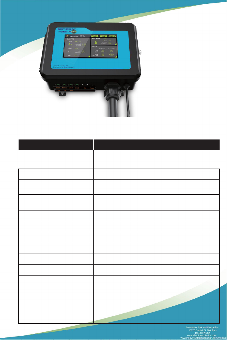
I.Overview of Master Environmental Control C-1
Master Environmental Control C-1 is the most complete and intelligent environment control
system that applies to professional indoor growth on the market. Featuring with CO23-in-one
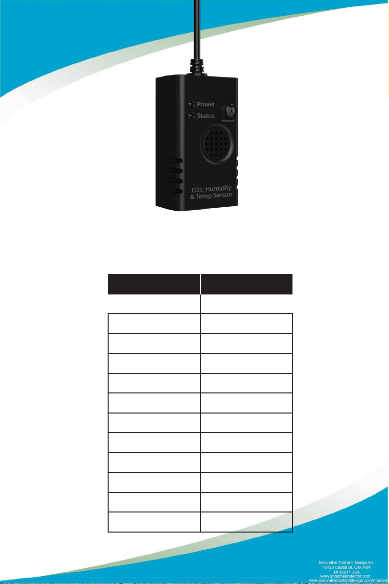
sensor (Temp/ Humid/-CO2/Light), Temperature and humidity sensor(with photocell), master
controller, LDA-1 Light adapter and AC station control modules, it can control up to 2 channels
of light (using LDA-1 adapter), 8 sensors (4 CO23-in-one sensors and 4 humid and temp
sensors), 4 temperature control devices, 4 humidity control devices and 4 CO2Generators.
Independent day and night control parameters can be set to maintain the optimal environmental
conditions around the clock for the crops to grow indoors. Master Environmental Control C-1's 3-
in-one sensor helps you to monitor temperature, humidity, and CO2level. You can install the
additional sensors to you help you better control and monitor the growing environment of the
plants.
You can easily set up daily lighting and specially designed light management in a convenient
manner. Master Environmental Control C-1 allows you to select the type of light (LED or HID) to
be controlled and can simultaneously employ 2 channels of independent or interlocked light
control logic in different modes to create multiple lighting layouts and growth spectra required
for plant growth. This system can efficiently monitor the temperature of the lighting system in
operation, to which it can control accordingly with advanced functions like auto-dimming,
overheat shutdown, sunrise, and sunset simulation.
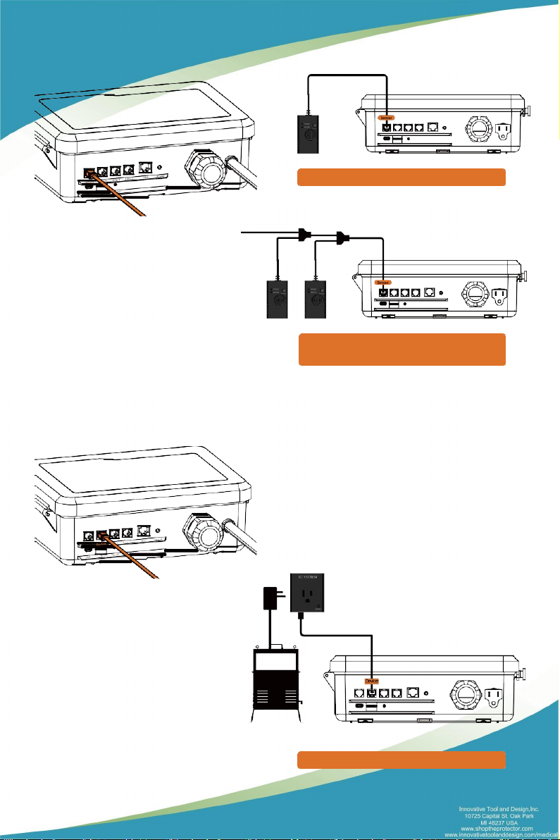
The Master Environmental Control C-1 has 10 control signals (24V AC) output for different
devices. By connecting to the connector panel board in the distribution box, the signal line
(24V AC) can control devices like Air Conditioner, Heater, humidifier, dehumidifier, and non-
dimmable light lines. The independent AC station can also be connected through Mobus
RS485 to control CO2supplement devices. Or it can control the air conditioner, heater,
humidifier, dehumidifier, and other devices through Mobus protocol RS485. Master
Environmental Control C-1 is an intelligent and flexible control system that provides growers a
complete indoor gardening solution for maximum yield.
WARNINGS:
1. Follow all local and national electrical codes for installation requirements.
2. Master Environmental Control C-1 is specially designed for indoor use only. Please use our
Master Environmental Control C-1 accessories to ensure its best performance.
2

I. Specifications of Master Environmental Control C-1
Master Environmental Control C-1
Product name Master Environmental Control C-1
Input Voltage AC 120V 60Hz 0.5A (can be customized)
AC 220~240V 50Hz 0.5A (can be customized)
AC signal output (PORT) 10-channel signal output: AC24V/50mA
Other signal output ports (RJ12) RJ12 x 4, 4-channel RS485 communication
Signal line output: DC24V, 1.0A
Operating Environment 5℃to 40℃;Relative humidity 80% no frosting;
Indoor Use Only
Network port RJ45
Dimensions 14” H x 17” W x 4” D (excluding length of power cable)
Power cord length ≈2m/6.5ft
Net weight 6.6 lbs
Gross weight 9.3 lbs
Package size 370x330x145mm / 14.6"x13.0"x5.7" (1 unit/box)
Accessories
4x Self-tapping screws
4x Ring Expansion Screw
1x 4 in 1 Sensor(CO2, Humidity, Temp & Light )
1x AC Station Module
1x Light Control Module
1x Y-splitter
2x RS485 communication extension cable 5.0m
3

4 in1 Sensor
(CO2, Humidity, Temp & Light)
Main parameters Default values
Gas detected
CO
2
Working voltage DC24V
Working current 30mA
CO2range 0~6000ppm
CO2accuracy ±(30ppm+3%)
Humidity range 0-100%RH
Humidity accuracy ±2%RH
Temperature range 32~158°F
/
0~70
℃
Temperature accuracy ±32.9°F / ±0.5
℃
Maximum quantity 4pcs per unit
Communication mode RS485 [Modbus-RTU]
Light Sensor Photocell
4

Main parameters Default values
Input Voltage AC120V 60Hz
Output Voltage AC120V/60Hz/MAX8A
Maximum power <1200W
Communication terminal RJ12 connector
Indicator Green LED
Maximum connections
quantity 32pcs
Communication Mode
RS485(Modbus-RTU)
Main parameters Default values
Input Voltage DC24V
Output Voltage 0~10V (DC)
Communication terminal RJ12 connector
Indicator Green LED
Maximum connections
per channel 20pcs
Communication Mode
RS485(Modbus-RTU)
AC Station socket module Light control module
5

Pressure-Type Stage Sensor
(Optionalaccessories)
Main parameters Default values
Power supply DC 24V
Output RS485
Range 0~5m water column
Pressure type Gauge Pressure
Compensation temperature 14~158°F / -10~70℃
Operating temperature -4~185°F / -20~85℃
Medium temperature -4~185°F / -20~85℃
Storage temperature -4~185°F / -20~85℃
Overload pressure 150%FS
Long-term stability ±0.2%FS / year
6

II. Warnings & Cautions
Save these instructions. These safety and operating instructions must be kept in a safe place for
future reference.
Heed all warnings. All warnings on this product and in the instructions must be observed closely.
Follow all instructions. All operating instructions must be followed.
If the instructions as provided by the manufacturer are not followed, May result in damage to
the product.
Install your controller at least 8 ft away from any devices that produce large amounts of electronic
noise, such as electronic ballasts or ozone generators.
Please cut off the power when wiring.
Please read this manual carefully before operating the Master Environmental Control C-1 .
Do not place metal objects such as paper clips and tools in the controller to prevent an electrical
shock hazard.
Before plugging in the Master Environmental Control C-1 , check whether the voltage of the socket
is consistent with the parameter described.
After the equipment is installed, perform the start-up test before operating it properly.
DO NOT use this controller near a water source. The controller is not water-proof or shock-proof,
and as such should not be exposed to direct water contact or extremely high moisture.
DO NOT attempt repair. Any factory serviceable parts of this controller are only to be repaired or
replaced by the manufacturer or other authorized agencies.
If the power cable insulation is broken, please stop using the product. Immediately unplug the
controller and contact the retailer from whom you purchased the unit.
The controller is equipped with a circuit breaker for short-circuit or over-current situations. The
circuit breaker will automatically shut down the product at once.
Do not block any ventilation openings.
This product is a Safety Class I Controller. The main plug should be inserted in a power socket
outlet only if provided with a protective earth contact. Any interruption of the protective conductor
inside or outside of the product is likely to make the product dangerous and is prohibited.
7

III. Installation Instructions
1. Install the Master Environmental Control C-1
Please install the controller at the place you are easily work with. You need to leave some space
for air ventilation use. Please keep controller away from flammable and explosive materials, such
as gasoline.
8

Sensor
Method 2: Multiple sensors are connected
through the Y-splitter branch.
Method 1: Connecting a single device.
2. Sensor Connection Instructions
Connect the sensor module to the “Sensor” port.
Connect more... Y-splitter
3. Devices Connection Instructions
Connect the devices module to the “Devices” port.
CO
2
Generator
Sensor
Method 1: Connecting a single sensor.
9

Metho
d
1:
Connectin
g a
sin
gle
main
contro
l
lig
ht
module
and sub-control light module
Method 2: Multiple lighting module are connected through
the
Y-Splitter branch.
.
Connect more... Y-splitter
Method 2: Multiple devices are connected
through the Y-splitter branch.
CO
2
Generator
4. Lighting Equipment Connection Instructions
Connect the lighting equipment to the “Line 1” and “Line 2” port.
连接更多...
连接更多...
10

Controller
Hea t
Cool
Hum i d i fier Dehu m i d i fi e r L ig h t
ALM
Maximum output
current
50mA
eachoutlet
01 02 03 0405 06 07 08 09 10
Power
PVC
pipe
5. Inner connection(AC24V) instruction
1). Loose the screw.
Counterclockwise
2).
Connect
a
PVC
threadi
ng
p
ipe
at at
the
bottom
of
the
controll
er
and
l
ock
it ti
ghtly.
Then
pass
the equi
pment
si
gnal
li
ne
through
the
PVC
pipe,
lock
the
terminal
,
and
then
i
nsert
the
terminal
i
nto the
correspondi
ng
i
denti
ficati
on
interface
i
nsi
de
the
control
l
er,
the
end
of
the
si
gnal
li
ne
connects
to
the
corresponding
i
nterface
i
n
the
power
di
stri
bution cabi
net.
Heat Cool Humidify Humidify Dehumidify
01 02 03 04 05
Dehumidify Light-1 Light-2 Alarm Alarm
06 07 08 09 10
Connect to power cabinet
11

For example: Connecting to humidifier
Connect to power cabinet
①
Connect
a
P
VC
threadi
ng
pipe
at at
the
bottom
of
the
control
ler
and
l
ock
it tightly;
②
Leave
the
Humi
di
fi
er
si
gnal
pipe
though
PVC
pipe,
l
ock
the
termi
nal;
③
Insert
the
terminal
i
nto the
“Humidi
fi
er”
i
denti
fi
cation
interface
i
nsi
de
th
e
controll
er,
the
end
of
the
si
gnal
l
ine
connects
to
the
correspondi
ng
i
nterface
in
the
power
di
stri
buti
on
cabinet.
3).Connect to power after all the connection are ready. Press the knob at “On”, close
the cover, screw tight.
Note:
1. Connect the Master Environmental Control C-1 to the power supply (Please refer to the
parameter table to ensure that the parameters of the power supply are consistent); set the
required parameters on the properly before using it.
2. The operation status of controller will be displayed on the screen, lease learn each signal well
before using.
3. Make sure that the probes (CO2sensor probe, and temperature and humidity sensor) are
connected to the probe socket on the bottom of the Master Environmental Control C-1 , and
check if the connector is properly inserted. Place the probe of the light sensor in the place to be
measured, with its front side facing the light source unobstructed.
WARNING: Do not disassemble the Master Environmental Control C-1 .
Please read the manual first. In case of any questions, consult your dealer.
(To ensure safety, please read this manual carefully and follow the instructions before
installation. If you have any questions, please contact us or consult with your dealer).
3
Clockwise
2
1
Power
PVC
pipe
12

IV.Installation Diagram
Devices
CO
2
Generator
CO
2
Tank
Fan
Lights
4x Humidity & Temp Sensor
Lights
4x CO
2
Sensor
Net
Power
AC 110V
USB TF Reset
Dehumidifier
Distribution box
Device s
13

Connection Guide
Bas
i
c
confi
gu
rati
on
i
n
th
e
s
tandard working
envi
ronment
wi
th
a
grow
area
of
200m
3
E
qu
i
p
m
en
t
Q
u
an
t
i
t
y
Purpose
Master Environmental
Control C-1
1
CO
2
four-in-one sensor
1
Monitoring
CO
2
parameters (Relative
CO
2
concentration value), relative temperature value,
relative humidity value, and light parameters
Temperature,HumidityandLight
three-in-one Sensor
1
Monitoring the
relative
temperature value,
relative
humid
i
ty
val
u
e,
and
l
ight
p
arameters
AC
Station Module
1
Used
to control the
CO
2
output device
(TANK
or
generator)
LDA-1 Light Control Module
2Used
to control the
CO
2
output device
(TANK
or generator)
R
S
48
5
C
a
b
l
e
S
e
v
e
r
a
l
E
x
t
en
s
i
on
li
ne
s
f
o
r
c
onne
c
t
i
ng ea
c
h
t
e
r
m
i
na
l
Note: Before installing the equipment, the user needs to consider the number of sensors and related
devices that need to be equipped based on the actual conditions of the planting area, for the heavy
current (110V-380V) devices in the circuits should be installed in the distribution box first.
1. Connect the sensor module to the Sensor port in series.
2. Connect the AC Station socket module to the Device port in series.
3. Connect the LDA-1 light control module to the LINE-1 port, which is the main light control line.
4. Connect the LDA-1 light control module to the LINE-2 port, which represents the auxiliary
light control line.
5. Connect the internal 10-channel port to the corresponding configuration in the distribution box
or related equipment that supports AC24V signals.
6. Before the connection, it is necessary to check if the positive and negative poles of the output
line are correct.
After the circuit connection is completed, plug in the power and turn on the device.
14

HID
08:30
18:30
FOLLOW
60%
Type: LED
ON at: 08:00
OFF at: 18:00
MODE: Auto
OUTPUTMAX: 80%
1.73VPD
CHANNEL 1 CHANNEL 2
28.5 ℃
Heat: 15.0 ℃
Cool: 35.0 ℃
Deadband: 5.0 ℃
LIGHT
TEMP
Protection:
High CO2 PPM 5000
1100
Target: 1200
Deadband: 200
44.7 %RH
Humidify: 30 %RH
Dehumidify: 90 %RH
Deadband: 5%RH
CO2PPM
CLIMATE
HUMI
SYSTEM IRRIGATION
SETTING STATUS
CONNECTION
STATUS
10:49:05
11-01-2020
Daytime Mode
V. Interface Instructions
Turn on the controller, the loading interface will be shown directly on the display. After the loading is
completed, the relevant information of the environment will be displayed on the homepage.
Function Description
Home Page
After the corresponding sensors are connected to the controller, the real-time data of the related
devices are displayed on the interface, including VPD, humidity, temperature, CO2, light, day and
night.
15

CO2Control
The PPM-UP mode, Fuzzy Logic mode and manual shutdown mode are available on the device.
By analyzing the CO2data read by the sensor, the relative CO2concentration in the environment can
be controlled and adjusted. The CO2control mode is composed of a generator [PPM UP] mode and
TANK [Fuzzy-Logic] mode. When the CO2concentration is lower than the start value, it will start the
output of the relevant devices (AC24V output and AC Station module); If it is higher than the end
value, it will stop the output of the relevant devices.
When the CO2concentration in the environment reaches the corresponding range, the output action
of the corresponding equipment will be stopped to achieve the goal of controlling CO2concentration
in the environment.
CO
2
Deadband
High
PPM
Protection
(Fuzzy Logic
/PPM UP)
Activate
Value
Target
value
Humidity control
The device can be set to humidify mode, dehumidify mode, synchronous humidify and dehumidify
control mode and idle mode.
After analysis of the humidity data read by the sensor, the humidity in the environment can be
controlled and adjusted. The humidity is controlled within a range. That is, when the humidity is below
the humidification value, the humidifier (AC24V output) will be started, and when it is above the initial
value, the dehumidifier (AC24V output) will be started.
After the humidity of the environment is within the corresponding range, the output of the correspond-
ing device is stopped to control the humidity in the environment.
Low Humi
protection value
Deadband Deadband
High Humi
protection value
Humidification
on value
Adaption
range
Dehumidification
on value
Temperature control
The heating mode, cooling mode, synchronous heating, and cooling mode and idle mode.
After analysis of the temperature data read by the sensor, the ambient temperature can be controlled
and adjusted. The temperature can be controlled within a range. When the temperature is below the
heating value, the heater (AC24V output) will be started; when it is above the initial value, the cooler
(AC24V output) will be started.
16

After the ambient temperature is within the corresponding range, the output of the corresponding
device will be stopped to realize ambient temperature control.
Low temp
protection value
Deadband Deadband
High temp
protection value
Heating
on value
Adaption
range
Cooling
on value
Day and night Setting
All sensors are equipped with a light sensor, which is used to determine whether the controller works
during the day or night. In this document, the daytime is defined as the time when the remote sensor
senses the light, and the nighttime is defined as the time when the light is not sensed in the room. The
actual time of the day does not affect the day or night mode controlled by Master Environmental
Control C-1.
When there are multiple probes, and the sensing status of different probes is inconsistent (for
example, one of the senses the day and the other two senses at night), it is decided by a simple majori-
ty. The sensor of day and night judges that the light intensity coefficient is determined by the device
and does not need to be set by the user.
The Master Environmental Control C-1 is preset with default day and night control parameters
(shown in the Factory Defaults and Control Limits section of this document) so that it can be used
immediately out of the box. The Master Environmental Control C-1 controller will display the date
symbol in the upper left corner of the day/night mode.
Day mode control: The Master Environmental Control C-1 controller outputs signals to the
corresponding device by monitoring the relative humidity, temperature, and CO2concentration in the
room based on the day control parameters, thus maintaining them at the required level in the
environment.
Night mode control: The Master Environmental Control C-1 controller outputs signals to the
corresponding device by monitoring the relative humidity, temperature, and CO2concentration in
the room based on the night control parameters, thus maintaining them at the required level in the
environment.
In night mode, only the CO2concentration monitoring and alarming are available, and the correspond-
ing output device will not be activated to save CO2.
Light dimming adapter control
The Master Environmental Control C-1 controller is equipped with two channels of independent or
interlocked light control logic; meanwhile, the main supplementary light line and the auxiliary
supplementary light line are available. In the Master Environmental Control C-1 system, a maximum
number of 20 light dimming adapter modules (LDA-1) are equipped per channel.
The LED-type and HID-type light are available. Moreover, there is an automatic high ambient over-
temperature detection mechanism (high-temperature shutdown function), which can turn off the light
when the temperature is excessively high.
17

HID
08:30
18:30
FOLLOW
60%
Type: LED
ON at: 08:00
OFF at: 18:00
MODE: Auto
OUTPUTMAX: 80%
1.73VPD
CHANNEL 1 CHANNEL 2
28.5 ℃
Heat: 15.0 ℃
Cool: 35.0 ℃
Deadband: 5.0 ℃
LIGHT
TEMP
Protection:
High CO2 PPM 5000
1100
Target: 1200
Deadband: 200
44.7 %RH
Humidify: 30 %RH
Dehumidify: 90 %RH
Deadband: 5%RH
CO2PPM
CLIMATE
HUMI
SYSTEM IRRIGATION
SETTING STATUS
CONNECTION
STATUS
10:49:05
11-01-2020
Daytime Mode
Automatic nutrient dosing and irrigation mode
Master Environmental Control C-1 controller is capable of running in conjunction with PHEC-B2
equipment, which is called Hydro-Plus mode. In this mode, the automatic nutrient dosing, automatic
water make-up, water level detection (EC, pH, water level, and water elevation), automatic irrigation,
automatic liquid dispensing switch, and high-water temperature alarm can be set.
VI. Operation Instructions
1. Power on
Turn on the , the LOGO will be automatically displayed in the interface, waiting for the data to be
automatically updated. After the update is complete, the monitoring interface will be shown.
After the devices are turned on, the real-time data of related devices will be displayed in the interface,
including VPD, humidity, temperature, CO2, light, day, and night.
The day and night status is displayed in the upper left corner of the interface, and the current time and
date are displayed in the top middle position of the interface. The time is shown in the format of HH:
MM: SS and the date are shown in the format of MM-DD-YYYY.
The day and night status is determined by a light sensor on the probe, which can detect the light
intensity.
2. System Setting
Press the system setting icon to enter the setting interface.
18

OFFON
Auto
Mode
Backlight
Unit ℃℉
Alarm
External Device
12-hour 24-hour
15:20:29
Time Setting
ListDevice
Sensor List
Date Setting
2017-03-22
System Setting
Update
System Version:
V1.00
Home
SYSTEM SETTING
In this interface, the system version, day and night time, date setting, time setting, 12/24-hour time
format, alarm signal output, temperature unit, automatic backlight switch, and backlight brightness can
be set.
You can navigate to other related interfaces via the interface on the right side.
Time format: Set the date format as MM-DD-YYYY and the time format as HH: MM: SS.
12/24-hour time format: 12-hour and 24-hour time format are available.
Alarm signal output: Enable and disable the alarm signal output.
Temperature unit: Set the temperature unit, in Fahrenheit or Celsius.
Automatic backlight switch: Enable the automatic backlight; waiting for 60 seconds, when the backlight
will be automatically turned off, and the screen saver will be shown.
Backlight brightness: Move the slider to adjust the brightness of the screen from 20% to 100%.
19
Table of contents
Other Innovative Lawn And Garden Equipment manuals
Popular Lawn And Garden Equipment manuals by other brands

Arbor Technology
Arbor Technology VA80140 Installation & Mounting Instruction

Spear & Jackson
Spear & Jackson TLEG05A Original instruction manual

Parrot
Parrot Flower Power user manual

Southern States
Southern States SP20PH48STA owner's manual

FITT
FITT FORCE Use and maintenance manual

Worx
Worx WG441E Safety and operating manual