Innowater RX User manual
MANUAL
Innowater RX
English version
Rev.06/19


1
WARNINGS
Before carrying out any installation or maintenance of the INNOWATER RX,
disconnect it from the mains power supply.
This appliance is not intended for use by persons (including children) that lack
experience and knowledge, unless they have been given supervision or
instruction concerning use of the appliance by a responsible person.
The installation of this device should be carried out by a qualified person.
The device should be located in the correct pool zone and connected to supply
via a power outlet that is protected by a residual current device (RCD) having a
rated residual operating current not exceeding 30mA.
The power outlet should have a degree of protection suitable for the pool zone
Ensure that equipotential bonding of all parts of the pool installation is carried
out.
During the installation phase, check that the voltage of the power supply
corresponds with the voltage indicated on the side of the appliance
Innowater Tratamientos Integrales del Agua S.L. will not be held liable for the
use of this device with inappropriate products.

2 INNOWATER PHRH
Page
1. Description.............................................................. 3
2. Installation ............................................................. 4
3. Start up................................................................... 5
3.1. Main screen ............................................................ 5
3.3. Start up. ON/OFF..................................................... 5
4. ORP configuration ................................................... 6
4.1. Setpoints................................................................ 6
4.2. ON/OFF mode (with chlorinator)................................ 8
4.3. Probe calibration ..................................................... 9
4.4. Factory calibration ..................................................10
5. Language .............................................................. 10
6. Contrast LCD ......................................................... 10

3
1. DESCRIPTION
The Innowater RX allows you to correct the ORP level of your pool. The device
monitors the ORP continuously by means of its ORP sensor and then, when needed,
sends a signal (dry contact) to activate an oxidant doser/producer device.
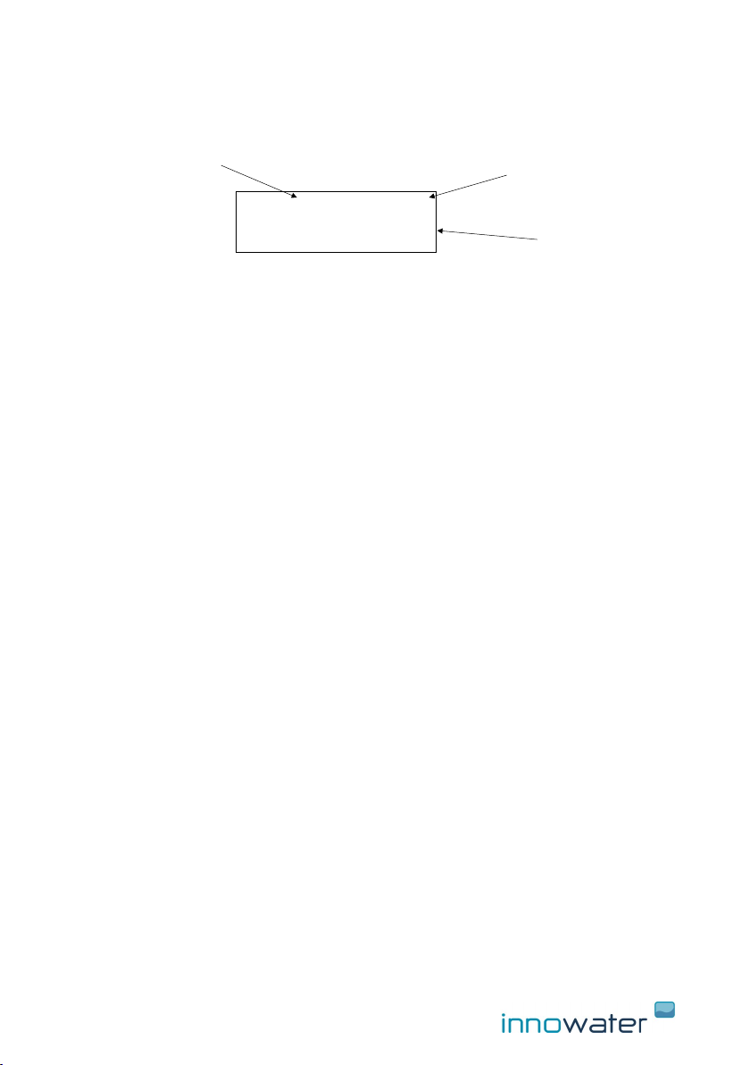
1. BNC socket for ORP probe
2. ORP control cable
3. 230 VAC power suply
4. Keypad
5. LCD display
1
23
4
5

4 INNOWATER PHRH
2. INSTALLATION
Controller
Install the device on the wall in easy to access location using the braquet provided.
Before attaching the bracket to the equipment, use the bracket to mark in the wall
the location of the holes you will need to make for the screws. Choose a location
close to the injection point.
ORP probe
Install the probe after the filter and BEFORE the chlorinator cell and as far as
posible from it. Try to choose a point in the circuit that never get empty of water,
because the probe deteriorates quickly when dry.
ORP control cable output
Control cable provides a dry contact to control the device. Depending on the
setpoint configured it can generate a proportional PWM duty cycle or an ON/OFF
signal.
If the device controls a saltwater chlorinator, setpoint must be configured
as an ON/OFF signal.
Connect the cable to the external control input of the chlorinator or use it to
activate a relay or other device.
If you use the cable to switch a voltage, do not exceed the following values :
Maximum voltage 230 VAC
Maximum current 1 A
5
3. START UP
3.1 Main screen
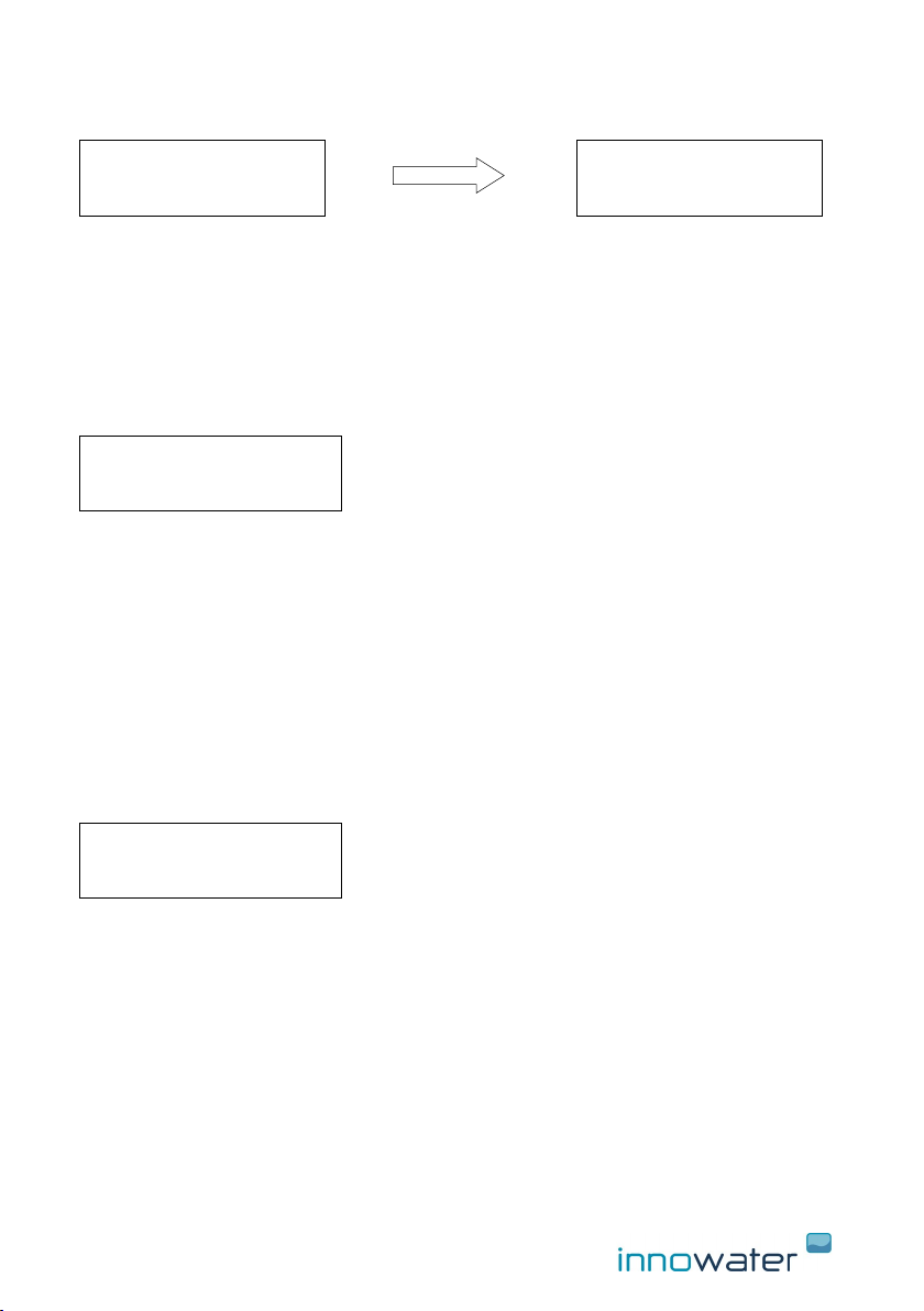
Main screen shows the following info:
(1) ORP measure
(2) ORP dosage percentage, calculated from the setpoints
(3) ORP output status
3.2 Start up— ON/OFF
To turn on the equipment press ON/OFF (MENU) for two seconds. Main screen
will appear.
To turn OFF, from the main screen, press ON/OFF (MENU) for two seconds.
Press Menu to access to the main menu. Use the arrows to scroll the different
functions. Press OK to enter in each sub-menu.
1
3
2
ORP 560mV 100%
Output ON

6 INNOWATER PHRH
4. ORP CONFIGURATION AND CALIBRATION
ORP control cable output
The control cable provides a voltage-free contact between its two wires. Depending
on the configuration of the setpoints this contact can generate a signal with a
variable work cycle (PWM) proportional to the measurement, or an ON/OFF signal.
To use this cable to control a Chlorinator, configure the output in ON/OFF mode.
Connect the cable to the external control input of the Chlorinator or connect it to
operate with a relay or other device.
If you use the cable to switch a voltage, do not exceed the following values:
Maximum admissible voltage 230 VAC
Maximum admissible current 1 A
If percentage, when calculated, is different of 0% or 100%, contact will open and
close according to a variable work cycle (PWM) in cycles of 100 seconds. For
example, if the calculated dosaje is 40%, contact will remain closed (ON) during first
40 seconds and open (OFF) for the rest 60 seconds.
Current status of this contact is shown permanently on display. When turning on the
device, it will wait for the ORP value to stabilize so, altough dosage is at 100%, ORP
output will remain OFF for a period of time. Also, the device has an hysteresis to
avoid fast changes and rebounds.
4.1 Setpoint
To enter press OK, it will show the following screen:
The calculation of the production is made by setting of two setpoints, A and B, and
the % of production that is desired for each of those points.
MENU
ORP Config.
1 Setpoints
A: RH 650mV 80%
B: RH 700mV 20%

7
- When the ORP is below the lower set point, the signal will work at its maximum
frequency.
- When the ORP is between both points, the chlorinator will send a proportional
signal defined by both points. For example, in the case of the figure, if the ORP is
at 675 mV the pump will dose at 50%.
- When the ORP is above the upper set point, the equipment will keep the output
OFF, at 0%.
You can set both points and choose the percentage of dosage for each of them. To
make this, press cursor with the MENU key in the parameter you want to modify
and scroll with the arrows to change the value.
Press OK key to save the data and Exit the sub-menu.
By setting the set points you will be defining at the same time the % of production
desired in each of those points, both dependent on the size of your pool. For
example, if your pool has a high volume you should establish high production
percentages. The response time in the measurement of the ORP of your pool can
be considered when establishing the set point B by cutting the signal before
reaching the desired ORP value. For example, to obtain an ORP = 750mV and avoid
overproduction, set the dosage cut to a somewhat lower value:
B: ORP 730mV 0%
We recommend to make periodic recalibrations of the ORP electrode.
A: RH 650mV 80%
B: RH 700mV 20%

8 INNOWATER PHRH
4.2 “ON/OFF” mode TO WORK WITH A SALT WATER CHLORINATOR
If you set the same ORP value in both points and dosage in A is 100%, output will
behave as a “ON/OFF” signal:
- When ORP is below the value, output will remain ON (closed contact)
- If ORP is above the value, output will remain OFF (open contact)
4.2.1 To work with a domestic INNOWATER salt water chlorinator, you
have to set the following parameters in the chlorinator:
Enter “Control Ext” in the main menu:
Activate external control:
In “2 Mode”, choose the option “Open = active”:
A: ORP 650 100%
B: ORP 650 0%
MAIN MENU
5 Control Ext
MENU CONTROL EXT
1 ON/OFF
OK
MENU CONTROL EXT
1 on /off
External control
ACTIVATED
OK
MENU CONTROL EXT
2 Mode
Mode
Open = active
OK
9
In “3 Production”, set 0%:
This way, when chlorinator receives the order to produce chlorine, it will do it at the
percentage chosen from the main screen. If the order is not to produce, it will
remain at 0%.
4.3 Probe calibration
The ORP probes require a calibration before their first use and then they need to be
calibrated periodically. It is because different probes can have different answers and
because the response of the same probe inevitably varies with time.
The calibration consists of measuring the response of the probe introducing it in two
buffer solution and recording this response in order to deduct the ORP (RH) of any
other solution, in our case, the ORP (RH) of the water in the pool.
The calibration of the probe is carried out using a buffer solution supplied (220mV)
and entering the sub-menu "3 ORP Calib.”.
Enter the sub-menu 3 ORP Calib. by pressing OK key, it will show the following
screen:
The value on the left (Lec:): indicates the current ORP (RH) value measured by the
probe. The value on the right, indicates the value of the buffer solution (220mV).
You can adjust this value using the arrows to adapt it to the temperature and the
sample used.
Insert the probe in the buffer solution 220mV, remove it slightly with the probe and
wait for a stable reading value to be reached.
Once the reading value has stabilized press OK key to save the calibration and exit
the sub-menu.
Next, remove the probe from the buffer solution 220mV, rinse its bottom with clean
water and shake gently to remove excess water.
MENU CONTROL EXT
3 Production
Production if
active 0%
OK
ORP Config.
2 ORP Calib.
ORP Calibration
Lec: 400mV 220

10 INNOWATER PHRH
4.4 Factory calibration
The submenu Factory calib, gives you the possibility to reset general calibration
parameters that correspond, approximately, with those of a new probe and which
are the ones programmed by the chlorinator from factory values. This can be useful
if you have saved successive calibrations and do not have the buffer solutions for a
correct calibration.
Press OK key to enter the sub-menu 5 Factory calib, it will show the following
screen:
Press OK key to set Factory values or MENU to Exit.
5. Language
Press OK key to enter and scroll with the help of the arrows to choose the desired
language.
Press OK key to confirm and Exit.
6. Contrast LCD
Press OK key to enter and scroll with the help of the arrows to choose the desired
LCD contrast.
Press OK key to confirm and Exit.
MAIN MENU
2 Language
Choose language
English
OK
LCD Contrast
- ■ ■ ■ ■ +
MAIN MENU
3 LCD Contrast
ORP Config.
3 Factory Calib.
Factory Calib.?
SI:OK EXIT:MENU
OK
Table of contents
Other Innowater Water Filtration System manuals


Popular Water Filtration System manuals by other brands


Stuart
Stuart Aquatron Assembly and operating instructions

Pentek
Pentek GS-6 instruction manual

Watts Premier
Watts Premier WP-4 BVC Installation, operation and maintanance manual

GE
GE GN1S04C Owner's manual and installation

Philips
Philips Pure Taste WP3861 manual

Beckett
Beckett Pond Filter RFPCOMBO Specifications