ATB HSA Manual

For a world with clean water
ATB - HSA
Installation/Operating Instructions

Installation/Operating Instructions ATB - HSA
ATB WATER GmbH, Südstraße 2, 32457 Porta Westfalica, Germany, www.atbwater.com /
Version: 07.11.2022 / Page 2 of 41
!!! IMPORTANT !!!
PRIOR TO USING THE UNIT
•Anybody involved MUST imperatively read and fully understand the unit’s O&M manual,
including the drive O&M manual.
•It is most important that the O&M manuals remain with the operator for future reference.
GENERAL
•No foreign objects such as hard materials, plastic bags, etc... are allowed in the basins.
These objects can cause extensive damage and/or for example create unbalance to the
impeller.
•In case of DOL start: Always use a soft starter for motors of 4 KW and more (see
chapter 4.4.3)
•Because of safety reasons it is absolutely forbidden to stand on
the float!
START-UP
•Please check all screwed connections (Motor, Flange/Power section, Cone-Cross) on
right tightness! Use a dynamometric key. Tightening torque is shown in table 1
(chapter 4).
•Please check the correct rotational direction of the unit.
•The motor may never be covered by a foam layer, neither partly nor completely.
High turbulence
Foam

Installation/Operating Instructions ATB - HSA
ATB WATER GmbH, Südstraße 2, 32457 Porta Westfalica, Germany, www.atbwater.com /
Version: 07.11.2022 / Page 3 of 41
Content
1. Safety regulations ....................................................................................................................... 4
2. Product overview ........................................................................................................................ 6
2.1. Description............................................................................................................................ 6
2.2. Working principle .................................................................................................................. 6
3. Receiving and handling............................................................................................................... 7
3.1. Receiving and acceptance.................................................................................................... 7
3.2. Handling (loading/unloading) ................................................................................................ 7
4. Assembly and installation............................................................................................................ 9
4.1. Assembly of aerator unit ....................................................................................................... 9
4.1.1. Assembly of power section and float in case the unit is delivered in 3 parts.................. 10
4.1.2. Assembly of the unit in case it is delivered in 2 parts .................................................... 10
4.2. Overview of mooring systems ............................................................................................. 11
4.2.1. Mooring with cables ...................................................................................................... 11
4.2.2. Hinged arm................................................................................................................... 12
4.2.3. Vertical guiding system................................................................................................. 15
4.3. Installation .......................................................................................................................... 16
4.3.1. Mounting sequence for installation with mooring cables................................................ 16
4.3.2. Mounting sequence for hinged arm system................................................................... 19
4.3.3. Mounting sequence for the vertical guiding system....................................................... 20
4.4. Electrical cable and wiring instructions................................................................................ 22
4.4.1. General wiring instructions............................................................................................ 22
4.4.2. Position of the electrical cable ...................................................................................... 23
4.4.3. Electrical connection diagrams ..................................................................................... 26
4.5. Start up ............................................................................................................................... 31
5. Maintenance ............................................................................................................................. 33
6. Storage...................................................................................................................................... 35
6.1. Temporary storage (= 1 up to 4 weeks) .............................................................................. 35
6.2. Long term storage (= more than a month)........................................................................... 35
ENCLOSURE I: Part list HSA aerator with standard stabilization cross ......................................... 36
ENCLOSURE II: Mooring cables and accessories .......................................................................... 37
ENCLOSURE III: General data ...................................................................................................... 38
ENCLOSURE IV: Declaration of conformity.................................................................................... 39
ENCLOSURE V: Maintenance sheet.............................................................................................. 40
ENCLOSURE VI: Motor O&M manual ............................................................................................ 41

Installation/Operating Instructions ATB - HSA
ATB WATER GmbH, Südstraße 2, 32457 Porta Westfalica, Germany, www.atbwater.com /
Version: 07.11.2022 / Page 4 of 41
1. Safety regulations
We will mention, in this chapter, the major kind of risks and dangers that might
occur, and the safety precautions to be taken.
•As mentioned in our declaration of conformity and in the warranty regulation, our aerator
can only be used when the installation, into which they need to be incorporated, is declared
conform to the Machinery Directive.
•If ATB did not deliver an explosion proof motor, it is forbidden to use the equipment in areas
where explosive gases might be present.
•At the moment of receipt and acceptance of the goods, you must always check that the
HELICAL IMPELLER can be rotated manually. Always be careful not to put a hand
between the HELICAL IMPELLER and the volute.
•Because of the weight of the goods, persons who are not directly involved should be kept
out of the handling area.
•Prior to the installation the lifting equipment must be inspected by an official authority, and
found suitable for the job, to allow safe loading, unloading and positioning.
•The complete electrical installation has to be designed in accordance with the European
standard EN 60204 concerning the electrical equipment of machinery, to NEMA, IEC or any
other locally valid directives concerning the electrical installation and connection of
machinery.
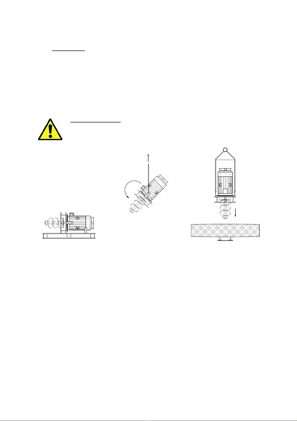
•Starting the aerator on dry land, to check the balance of the motor and HELICAL
IMPELLER or to do a last greasing, should not be done without taking radical safety
provisions and has to be performed by a qualified person. Should any abnormality occur,
the aerator must be switched off immediately.
•During the installation of the aerator, all necessary personal protection equipment has to be
at the disposal of all persons involved in the assembly and installation of the equipment.
It is essential to check that the safety switch of the unit that needs to be installed,
and also of all other units located in the basin where the unit needs to be installed,
has been switched off and locked in this position during all work on the electrical
installation, during maintenance or repairs, and during installation.
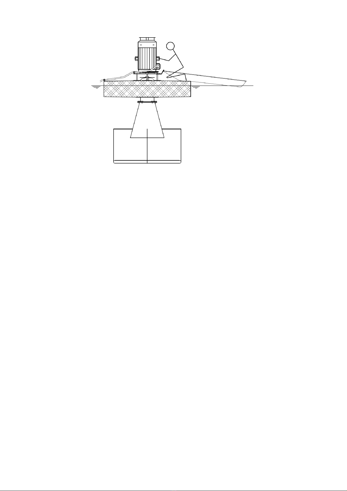
As a safety precaution and also to prevent the unit from tipping, it is absolutely
forbidden to stand on the unit. It is possible to reach the aerator by using a boat as
shown on drawing 1: “Reaching the unit by using a boat.”.
•During any intervention on the electrical installation, maintenance and/or repairs of the unit,
a second person has to be present to verify the safe intervention and eventually assist.
ATB WATER GmbH is not responsible for any kind of incidents.

Installation/Operating Instructions ATB - HSA
ATB WATER GmbH, Südstraße 2, 32457 Porta Westfalica, Germany, www.atbwater.com /
Version: 07.11.2022 / Page 5 of 41
Drawing 1: Reaching the unit by use of a boat
During the start up of the aerator nobody may stand be in a boat near the aerator.
Make sure that all safety precautions are taken to make sure that nobody can fall into the water.

Installation/Operating Instructions ATB - HSA
ATB WATER GmbH, Südstraße 2, 32457 Porta Westfalica, Germany, www.atbwater.com /
Version: 07.11.2022 / Page 6 of 41
2. Product overview
2.1. Description
The HSA floatable surface aerator generally consists of a top mounted electrical motor, which
drives a helical impeller.
The electrical motor is mounted on a flange support, which at its turn is mounted on the stainless
steel float.
A cone (possibly equipped with crossplates) is mounted below the float, at the cylindrical volute tube
and enables an ideal flow into the volute and impeller.
The HSA offers following advantages:
•low investment cost for the complete installation
•simple and quick installation
•high performance in oxygen transfer
•intensive mixing
•no need to empty the tank, neither for the installation, nor for the maintenance of the
equipment
•excellent reliability
2.2. Working principle
The HSA functions as an open pump. The mixed liquor of wastewater and activated sludge is
aspirated via the suction pipe. The helical impeller pumps the liquid axially up through the
cylindrical volute, bends the liquid flow from axial to radial, and ensures that maximum kinetic
energy is transferred to the water surface.
Drawing 2: Working principle
Whilst transferring the maximum kinetic energy to the water, the helical impeller achieves a high
performance in pumping and oxygen transfer. Due to the design of the impeller, the forces on the
bearings are very low, so standard bearings can be used.
Spray
High turbulence

Installation/Operating Instructions ATB - HSA
ATB WATER GmbH, Südstraße 2, 32457 Porta Westfalica, Germany, www.atbwater.com /
Version: 07.11.2022 / Page 7 of 41
3. Receiving and handling
3.1. Receiving and acceptance
•Check the goods for visible damage before unloading.
•Check if the HELICAL IMPELLER can be rotated manually.
If you have any remarks, please note them on the forwarding documents, and contact ATB
immediately.
The unit is forwarded in 2 or 3 parts:
•Power section (= motor, flange support and HELICAL IMPELLER)
•Float
•Cone (eventually equipped with crossplates)
In case of 2 parts, float and power section are pre assembled.
Drawing 3: Major parts for transport
3.2. Handling (loading/unloading)
Be careful when handling this type of heavy, precision equipment to avoid damage to it or other
equipment, or injure any person involved. Persons that are not directly involved in loading/unloading
should be kept out of the handling area.
Only the eyes mounted on the motor, and the special lifting brackets mounted on the flange support,
can be used for lifting respectively the power section and the complete unit. Damage to the unit may
occur if incorrect lifting practices are used.
Motor
Impeller
Cone
Flange support
Float
Crossplate

Installation/Operating Instructions ATB - HSA
ATB WATER GmbH, Südstraße 2, 32457 Porta Westfalica, Germany, www.atbwater.com /
Version: 07.11.2022 / Page 8 of 41
The lifting equipment used, should have been inspected and approved by an official authority prior
to unloading the truck in order to allow safe handling.
CAUTION:
Never lift with only one motor eye or with the mooring anchors on the float!
Drawing 4: How to lift the unit

Installation/Operating Instructions ATB - HSA
ATB WATER GmbH, Südstraße 2, 32457 Porta Westfalica, Germany, www.atbwater.com /
Version: 07.11.2022 / Page 9 of 41
4. Assembly and installation
IMPORTANT NOTE:
Apply anti-seize grease (f.ex. Mi-setral-7N) on all bolts prior to assembly.
IMPORTANT NOTE:
All screwed connections (Motor, Flange/Power section, Cone-Cross) have to be
tighten by using a dynamometric key. Tightening torque is shown in table 1 (see
below).
If the unit is supplied in 3 parts, use the delivered Loctite when assembling the
power section to the float.
Screw Tightening torque
[Nm]
M 8 21,4
M 10 44
M 12 74
M 14 119
M 16 183
M 18 260
M 20 370
M 22 488
M 24 608
M 27 728
M 30 848
Table 1: Tightening torque
4.1. Assembly of aerator unit
As mentioned earlier, the unit is forwarded in 2 or 3 parts:
•power section (= motor, flange support and HELICAL IMPELLER)
•float (already assembled with power section in case of 2 parts)
•cone (possibly equipped with crossplates)
The unit should be assembled on flat and stable ground. It is mandatory to use lifting hooks, which
have safety locks.
IMPORTANT NOTE:
The assembled surface aerator can be placed on the bottom of the basin during
installation. It must be secured against tipping with the help of the guiding system. If
this is not possible, the aerator must be secured by a support structure made by the
customer.
Permanent set up of the assembled aerator on the bottom of the basin or
permanent storage in this condition is not permitted. If, despite this, the aerator is to
be stored or set up in the assembled state for a longer period of time, the weight of
the float/ motor must be relieved from the intake cone/cone cross by means of a
suitable support structure provided by the customer.

Installation/Operating Instructions ATB - HSA
ATB WATER GmbH, Südstraße 2, 32457 Porta Westfalica, Germany, www.atbwater.com /
Version: 07.11.2022 / Page 10 of 41
4.1.1. Assembly of power section and float in case the unit is delivered in 3 parts
•Carefully lift the power section (which is generally transported in horizontal position) by means
of the motor eye, to bring it in vertical position. The lifting eyes on the motor on which the
attachment will be made must be connected diagonally.
•Pay special attention to the impeller, so that it is not touched/hit during handling.
•Slide the impeller slowly and vertically down into the volute of the float, and position the flange
support such that the positioning stud on the top flange of the float coincides with the recess
made in one of the connection flanges of the flange support.
•Insert the fixation bolts but don’t turn them tight yet.
•Verify if the impeller can turn free into the volute, without touching.
•If so, tighten the bolts, and afterwards recheck if the impeller turns freely.
IMPORTANT NOTE:
Every power section, float, and cone/cross has a serial number. Make sure not to
mix the parts of different units, especially not the power sections and floats, as this
might result in assembly and operation problems.
Drawing 5: Assembling power section and float
4.1.2. Assembly of the unit in case it is delivered in 2 parts
Check if the impeller turns freely in the volute.
Power section with float is to be positioned on top of the cone and fixed to it by means of the flange-
flange coupling with nuts and bolts. Always use self-locking nuts!
A positioning stud on the flange of the cone / cross and a hole in the flange of the float ensures the
correct positioning of the cone cross and float. It is strongly recommended not to start the aerator
before the aerator is completely installed in accordance with the instructions described by ATB.
Starting the aerator on dry land should not be done without making radical safety provisions.
Should any abnormality occur, the aerator must be switched off immediately!

Installation/Operating Instructions ATB - HSA
ATB WATER GmbH, Südstraße 2, 32457 Porta Westfalica, Germany, www.atbwater.com /
Version: 07.11.2022 / Page 11 of 41
Drawing 6: Assembling the aerator
4.2. Overview of mooring systems
Depending on the water level variations, we distinguish the following mooring systems, ranked
according to increasing water level variations:
•Mooring with cables, eventually combined with springs, for small water level variations
•Mooring with hinged arm, with or without lateral cables
•Mooring with sliding attachments, for large water level variations
When you are using a different kind of mooring system, due to a specific situation, this must
always be done in dialogue with, and with the approval of ATB.
Any warranty claim for damage to the unit or others, due to a faulty designed mooring system, not
approved by ATB, will be void.
4.2.1. Mooring with cables
There are usually three anchors, which are equally spread over the periphery of the float. Optionally (if
ordered) the aerator can be supplied with 4 mooring cables.
In case of limited water level variations, one can simply mount a mooring spring in series with the
mooring cables. The decision to adopt this solution will however depend on the geometry of the basin
and the position of the aerator in the basin.
Aerator section
Cone / Cross
Self-locking Nuts!

Installation/Operating Instructions ATB - HSA
ATB WATER GmbH, Südstraße 2, 32457 Porta Westfalica, Germany, www.atbwater.com /
Version: 07.11.2022 / Page 12 of 41
Basin Wall
Mooring Anchor
Quick Link
Retention Spring
Thimble
Rope Clips
Mooring cable
Drawing 7: Mooring cables, thimbles, clips, quick connectors and springs
If the water level-variation exceeds 1 meter, please contact ATB to agree on the suitable guiding
system. ATB should always approve this guidance system.
Any warranty claim for damage to the unit or others, due to a faulty designed mooring system not
approved by ATB, will be void.
4.2.2. Hinged arm
This mooring system is ideal in following cases:
•For limited water level variations, which however may be more than for the mooring system
with cables and springs.
•In case of high above ground tanks, to limit the number of required access locations for
maintenance.
•To simplify the mooring system and accessibility when a large number of aerators are used.
The hinged arm connects the aerator to the side of the basin and allows the unit to follow the water
level variation.
If the water level variation would be such that the aerator would come too close to
the wall and the aerator spray would consequently hit the basin wall under a
certain minimum water level, one should stop the aerator from that level down.
It is of high importance that, during the movement caused by the varying water
level, the arm never rests on the wall-side, as it can cause the arm to bend and
break.
If, for whatever reason, the water level has to be lowered, the aerator has to be
removed first.

Installation/Operating Instructions ATB - HSA
ATB WATER GmbH, Südstraße 2, 32457 Porta Westfalica, Germany, www.atbwater.com /
Version: 07.11.2022 / Page 13 of 41
When the hinged arm is connected to the assembled HSA, the aerator + arm
assembly is not stable outside the basin!
The hinged arm mooring system consists of 2 or 3 parts, depending on the execution. There are
several possible executions, but the system always consists of the following:
•wall fixation part
•arm, provided with hinge part at both ends, for hinged connection to the wall fixation part at
one side, and to the aerator at the other side
a) Hinged arm, basic execution
This execution simply consists of a wall fixation and an arm.
If important flows are expected in the basin (f. ex. in oxidation ditch), extra mooring cables should
be foreseen to reduce the sideward forces on the arm.
Arm
Wall fixation (installed on the side or on the top)
Drawing 8a: Hinged arm, basic execution
b) Hinged arm with 2 degrees of freedom
In some cases, the wall fixation has two different hinge axles, allowing vertical and horizontal
movement of the arm. In this execution, the arm will always be equipped with mooring cables to
hold it in the operational position, while reducing the forces on arm and hinge.
The cables will also allow pulling the aerator to the side for maintenance.

Installation/Operating Instructions ATB - HSA
ATB WATER GmbH, Südstraße 2, 32457 Porta Westfalica, Germany, www.atbwater.com /
Version: 07.11.2022 / Page 14 of 41
Mooring Arm
Wall fixation installed on the top of the wall
Mooring cable
Lifting bracket (optional)
Mooring arm
Mooring cables
Mooring anchors
Drawing 8b: Hinged arm with 2 degrees of freedom

Installation/Operating Instructions ATB - HSA
ATB WATER GmbH, Südstraße 2, 32457 Porta Westfalica, Germany, www.atbwater.com /
Version: 07.11.2022 / Page 15 of 41
4.2.3. Vertical guiding system
When the water level variation is such that the cable length variation cannot be covered by one
compression spring, or that the angle variation between the cable/hinged arm and the water line is
too important, the mooring with a vertical sliding attachment should be used.
Drawing 9: Vertical guiding system
Guiding brackets
Guiding bars
(2, 3 or 4 tubes)

Installation/Operating Instructions ATB - HSA
ATB WATER GmbH, Südstraße 2, 32457 Porta Westfalica, Germany, www.atbwater.com /
Version: 07.11.2022 / Page 16 of 41
4.3. Installation
As a safety precaution, the installation of the unit must always be performed by at
least two persons.
Once the unit is completely assembled, the entire unit can be lifted by the lifting lugs welded to the
motor support, and positioned in the tank. Be sure that the cables or chains are not twisted. Also
make sure that the lifting chains can not damage the aerator.
IMPORTANT NOTE:
The assembled surface aerator can be placed on the bottom of the basin during
installation. It must be secured against tipping with the help of the guiding system. If
this is not possible, the aerator must be secured by a support structure made by the
customer.
Permanent set up of the assembled aerator on the bottom of the basin or
permanent storage in this condition is not permitted. If, despite this, the aerator is to
be stored or set up in the assembled state for a longer period of time, the weight of
the float/ motor must be relieved from the intake cone/cone cross by means of a
suitable support structure provided by the customer.
The following major positioning rules need to be respected:
•Before mounting the aerator in the basin, you are advised to check with ATB to avoid incorrect
positioning.
•The aerator has to be placed in such a way that the openings in the spray are perpendicular to
the side (wall) of the basin.
•The power cable should be directed in one of the openings of the spray. Incorrect location of
the power cables can cause splashing on the motor.
•Never place any construction directly into the spray of the aerator to avoid splashes towards
the motor.
As a safety precaution and to prevent the unit from tipping, it is prohibited to stand
on the HSA float at any time.
In all mooring cases, make sure to limit the over length of cable and to fix the
electrical cable in such a way that it can not be aspirated by the HSA helical
impeller in any position between the minimum and maximum water level!
4.3.1. Mounting sequence for installation with mooring cables
If the electrical cable and mooring cables are supplied by ATB, they will normally already be
connected to the HSA. If this is not the case, the mooring cables have to be attached to the
mooring anchors at float side, and the electrical cable has to be connected inside the junction box
of the motor, prior to the installation in the basin.
Place the aerator in the water near shore, wall or platform and loosen the lifting cable or chains.
Using the mooring cables, the unit can be pulled into its final position.
The mooring cables have to be attached to the mooring anchors at the side of the basin.

Installation/Operating Instructions ATB - HSA
ATB WATER GmbH, Südstraße 2, 32457 Porta Westfalica, Germany, www.atbwater.com /
Version: 07.11.2022 / Page 17 of 41
Locate the mooring points so the angle enclosed by any 2 subsequent cables is equal (120° in
case of 3 cables; 90° in case of 4 cables).
Locate the mooring points (at basin side) in such a way that the angle enclosed by any 2 subsequent
cables is equal (120° in case of 3 cables; 90° in case of 4 cables).
In case of limited water level variations, one or more compression springs might be requested in
between the cable ends and the mooring anchors at basin side. Please check the tension in the
cables regularly.
If the water level-variation is such that 1 standard spring is not enough to compensate the variation of
distance between the mooring anchor at basin side and float, please contact ATB to agree on the
suitable guiding system. This guiding system should always be approved by ATB.
In case no variation of the water level occurs and no springs are used, the angle between the mooring
cable and the water surface should not exceed 15°. (Ratio between the height of mooring location
above the water surface and the cable length should be ± 1/4).
Following mooring means are available for basin side fixation:
•Mooring Anchor, for Concrete Walls or Steel Tanks
Drawing 10: Mooring Anchor for concrete wall or steel tank
•Mooring post, for earthen basins
Drawing 11: Mooring post for earthen basins
With or without concrete
depending of the stability of
the ground

Installation/Operating Instructions ATB - HSA
ATB WATER GmbH, Südstraße 2, 32457 Porta Westfalica, Germany, www.atbwater.com /
Version: 07.11.2022 / Page 18 of 41
The strength of each one of these mooring systems and their fixation should overpass the strength of
the mooring cable provided. Selection and provision of these mooring methods should be submitted to
ATB for approval.
It is advisable to follow the instructions in enclosure II for a correct assembly of the mooring
cables.
The mooring cables are used to keep the surface aerator in the right place in the basin or in the
lagoon.
The device must "all the time" float independently on the water surface.
Mooring cables must be detached if the water level would drop below the minimum allowable level,
e.g. when the tank should be emptied or during a particular maintenance work.
Mooring cables can in no way serve to raise the device above the water, or to keep the device
above the water level.
ATB cannot be held liable for accidents caused by non-compliance with these instructions.
Once the HSA is in its final position, the mooring cables can be tensioned. A sag of ±2cm per
meter mooring cable is recommended. Excessive tightening may damage the cables in the long
run. Under no circumstances mechanical tools are to be used to facilitate additional tightening.
If the HSA is in the correct position, the electrical cable can be connected to the junction box on the
side of the basin. Make sure to attach the electric cable to an anchor before it enters the junction
box, to avoid that the electric cable pulls at the cable gland entering the junction box.
We refer to section 4.4. for further electrical connection details.

Installation/Operating Instructions ATB - HSA
ATB WATER GmbH, Südstraße 2, 32457 Porta Westfalica, Germany, www.atbwater.com /
Version: 07.11.2022 / Page 19 of 41
4.3.2. Mounting sequence for hinged arm system
a) Basic hinged arm or hinged arm with 2 degrees of freedom
Once the aerator unit is assembled according to the description under 4.1. “Assembly of aerator
unit”, the mooring arm needs to be mounted to the aerator (with or without the mooring cables,
depending on the execution).
Connection detail:
Bolt
Bush
Washer
Washer
Nut with nylon insert (optional: nut + spring washer with split pin)
Drawing 12a: Mounting of the hinged arm to the aerator
Next, attach the power cable along the hinged arm, whereby care must be taken to leave enough
spare cable length between the motor junction box and the beginning of the arm at aerator side
(See drawing 19b.:”Position of the power cable with hinged arm”).
Now you may lift the aerator and its hinged arm, and next lower it in the basin.
For vertical lifting of the unit, and to avoid handling damage, a double chain
should be used (see drawing).
Drawing 12b: Lifting of the hinged arm

Installation/Operating Instructions ATB - HSA
ATB WATER GmbH, Südstraße 2, 32457 Porta Westfalica, Germany, www.atbwater.com /
Version: 07.11.2022 / Page 20 of 41
Once the aerator is floating, you can connect the other end of the arm to the wall fixation part,
which should have been mounted previously. If used, attach the mooring cables to the wall by
means of the mooring brackets, which should be located somewhere in the prolongement of the
hinge axis line.
Drawing 12c.: Mounting of the hinged arm to the wall fixation
If the HSA is in the correct position, the electrical cable can be connected to the junction box on the
side of the basin. Make sure to attach the electric cable to an anchor before it enters the junction
box, to avoid that the electric cable pulls at the cable gland entering the junction box.
We refer to section 4.4. for further electrical connection details.
4.3.3. Mounting sequence for the vertical guiding system
If the electrical cable is supplied by ATB, it will normally already be connected to the HSA. If this is
not the case, the electrical cable has to be connected inside the junction box of the motor, prior to
the installation in the basin.
If ATB doesn’t supply the guiding posts, it is imperative that the customer either produces these
posts according to the indications he receives from ATB, or sends information about the exact
location of existing posts, as well as the diameter of those posts, in order to foresee the
appropriate sliding arrangement.
The guiding posts need to be fixed to the floor of the basin and the basin side, prior to the installation
of the HSA into the basin. For the installation of these posts, assuming these are part of the ATB
delivery, a separate installation drawing will be sent, indicating the exact location of these posts.
When installing / fixing the guiding tubes, it is essential to ensure that the tubes are
vertical and parallel to each other (regardless of the position of the tank bottom), so that
the guiding tubes have the same distance to each other at every height, so that the unit
can move unhindered up and down between the guiding tubes.
Before commissioning, check that the unit can slide between the tubes over the entire height without
any problem.
Table of contents
Other ATB Water Filtration System manuals
Popular Water Filtration System manuals by other brands

Aquion
Aquion EFP10 Installation & operating instructions

Jandy
Jandy TruClear Installation & operation manual

Nimbus Water Systems
Nimbus Water Systems CS-3 manual

3P Technik
3P Technik 1000300 Operating and assembly instructions

Weco
Weco MX Series manual

Aeroex Technologies
Aeroex Technologies ARO-2500 Installation & service manual

Premier Tech Aqua
Premier Tech Aqua Rewatec Fl-1 Installation and operating instructions

CPI
CPI Olympic SF119 owner's manual

Kongskilde
Kongskilde RVS 5000 Operator's manual

US Water Systems
US Water Systems 300-H-4510-BG-222-KIT owner's manual

PUR
PUR PPT700 Series user manual

EcoWater
EcoWater 3500 Series owner's manual