Tech support is readily available if needed
Phone: 866.528.2804
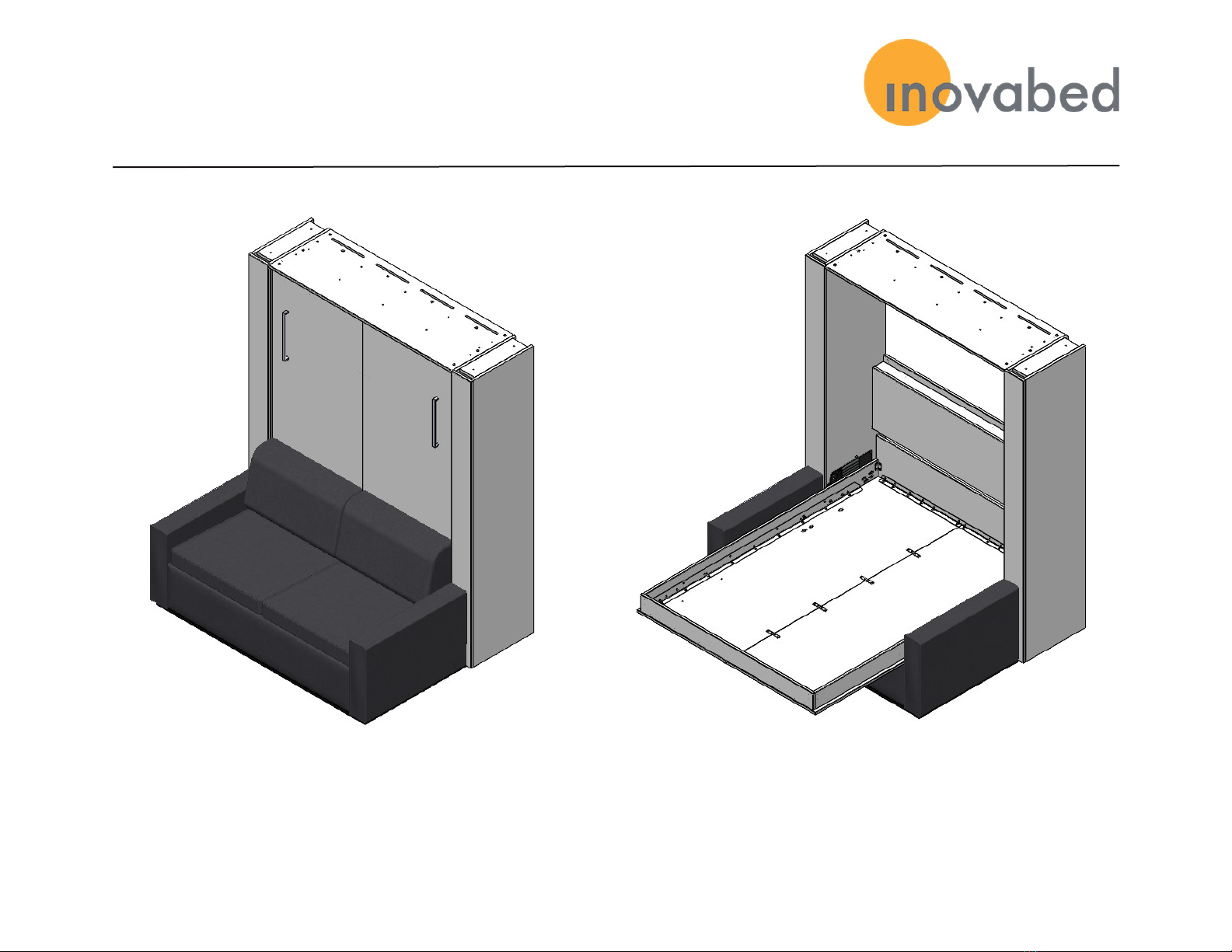
Sofa-WallBed|ASSEMBLY MANUAL
PLEASE NOTE: Your Bed may look dierent
than what is shown in the pictures and
Videos throughout this manual
1. To adjust the number of springs,you will need to temporarily “walk”
the cabinet and sofa forward until it is around two feet from the wall.
Do not move the unit by grabbing the sofa arms as it may damage it.
Use the cabinet instead.
2. Working behind the cabinet, add or remove springs from the spring
mechanisms as needed. The top and bottom springs are installed
with the hooks facing inward so they are a little easier to remove.
The nal arrangement of springs should be symmetrical above and
below the center of the mechanism. for example,if you start with (8)
springs, the center space will be empty. If you remove a spring, you
should take it o the top, but you should also move the bottom spring
to the center space. Ideally the left and right spring mechanism
should have the same number of springs.
3. Push the cabinet and sofa back in place against the wall and test the
raising and lowering of the bed.
HOW TO
ADJUST TENSION: STEPS FOR ADJUSTMENT:
To adjust the tension of the Sofa-WallBed:
The factory has installed the proper number of springs
based on our estimated weight of typical mattresses.
Your mattress weight may vary from these estimates.
With the springs provided, the bed platform should be
very easy to raise and lower.
If it is too light, it will oat up a little instead of staying
down in the bed position. In this case you will need to
remove one of the springs.
If it is too heavy,it will be too dicult to lift and you will
need to add a spring.
How It Works