Tech support is readily available if needed
Email: support@inovabed.com
Phone: 866.528.2804
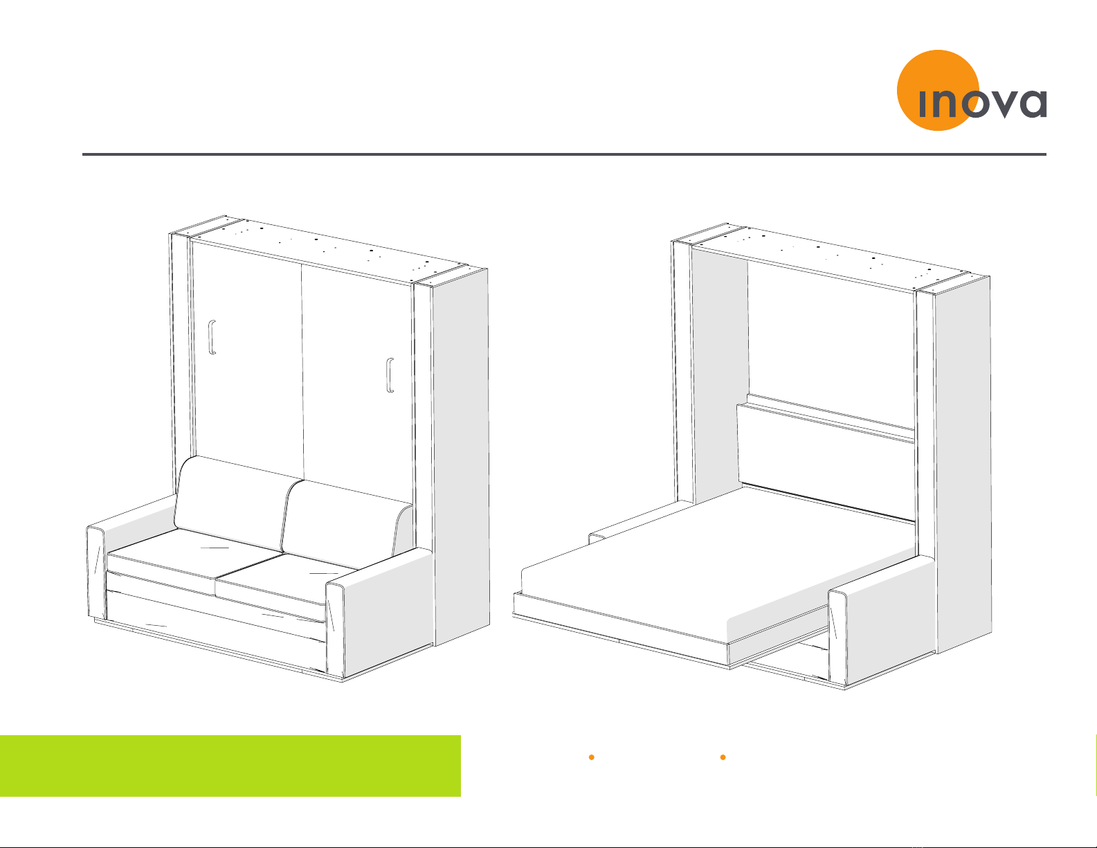
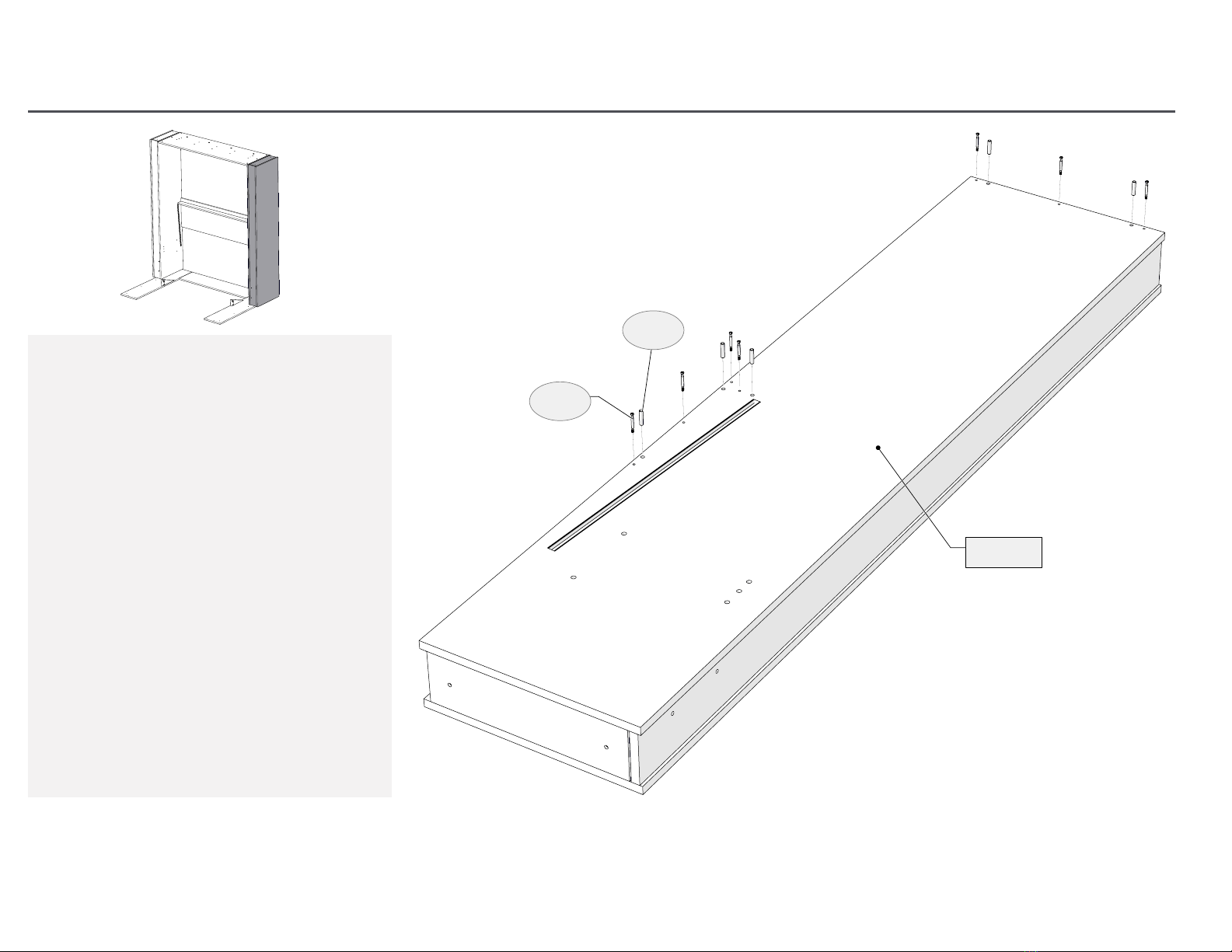
Sofa-WallBed |ASSEMBLY MANUAL
PLEASE NOTE: Your Bed may look different
than what is shown in the pictures and
videos throughout this manual
ROOM READINESS
CHECKLIST
• Check room to confirm the ceiling, floor,
and walls in the room are finished
and completed
• Select the wall and location in which the
Bed will be placed
• Measure the length of the wall and height
of ceiling to confirm the Bed will fit
TIP: You may want to remove existing
baseboard that is located on the wall where
the Bed will be installed. By removing the
baseboard, it will allow for a tighter fit
against the wall (custom units may already
have a notch for baseboard – see shop
drawings, if applicable).
• Locate any electrical outlets on the wall
that may be covered up by the Bed
• Clear out any items in the room so you
have a clear path to the wall and an open
area to assemble the Bed
• If the flooring is hard, lay down some
furniture blankets, sheets of cardboard, or
other cushioning material to prevent parts
from being scratched.
• Locate the maress that will be used with
this Bed; the specific maress is required
for proper adjustment of the Bed and
completion of the assembly
QUICK START GUIDE (CONT.)