Esu SwitchPilot 3 51830 User manual
Instruction manual
1. Edition, January 2021
P/N 00221-24443
From Decoder Firmware 3.0.9
51830 SwitchPilot 3
SwitchPilot 3
SWitch Pilot

2
1. Declaration of Conformity ...................................... 3
2. WEEE-Erklärung ....................................................... 4
3. Important Notes ...................................................... 4
4. Features .................................................................. 5
4.1. General Features...........................................................5
4.2. Technical Data...............................................................5
4.3. Scope of delivery...........................................................5
4.4. Operating modes..........................................................6
4.4.1. Pulse operation..........................................................6
4.4.2. Operating PECO turnout drives .................................7
4.4.3. K83 operation (momentary action mode)...................7
4.4.4. K84 Operation (Bistable continuous operation) ..........8
4.4.5. Alternate flasher mode ..............................................9
4.4.6. Operating mode switch .............................................9
5. Connection to the digital system ......................... 10
5.1. Terminals ....................................................................10
5.2. Power supply by the digital system..............................11
5.3. External power supply ...............................................11
5.4. Wiring the outputs .....................................................12
5.4.1. Solenoid turnout drives............................................12
5.4.2. Daylight signals with incandescent lamps or LEDs ....12
5.4.3. Uncoupling tracks....................................................13
5.5. Wiring the feedback contacts .....................................13
5.6. Connecting the SwitchPilot Extension .........................14
5.6.1. Relay outputs...........................................................14
5.6.2. Motorized turnout drives .........................................14
5.6.3. LGB® Turnout drive .................................................15
5.6.4. Turnout frog polarization .........................................15
6. Configuration with OLED...................................... 16
6.1. Relationship between accessory addresses and turnout
numbers ............................................................................16
6.1.1. Assigning turnout numbers......................................17
6.2. Introduction to the operating structure.......................18
6.3. Address mode for ROCO® command stations ............19
Content
6.4. Configuring outputs ...................................................19
6.5. Setting fade-in and fade-out times..............................20
6.6. Status information ......................................................20
6.6.1. Display software version & track voltage ..................20
6.6.2. Displaying output states...........................................20
6.6.3. Viewing feedback input states .................................21
7. Configuration with LokProgrammer.................... 21
8. Configuration POM (Programming on the Main)22
8.1. Connection to the digital system.................................22
8.2. Reading and writing CVs with POM ..........................22
9. Configuration with the programming track........ 23
9.1. Connection to the digital system.................................23
9.2. Read & Write CVs .......................................................23
10. Learning turnout numbers from command station ...23
11. RailCom® ............................................................. 24
11.1. RailCom® Configuration ........................................24
11.2. Turnout status feedback with the ECoS.....................24
12. Reset to factory default (decoder reset)............ 25
12.1. With the programming button..................................25
12.2. With DCC systems ....................................................25
12.3. With the display........................................................25
14. Support ................................................................. 26
16. Solenoid address & turnout numbers ................ 30
17. List of all supported CVs...................................... 32
18. Change history..................................................... 34
19. Warranty certificate............................................. 35

3
Declaration of Conformity
1. Declaration of Conformity
The manufacturer, ESU electronic solutions ulm GmbH & Co. KG,
Edisonallee 29, D-89231 Neu-Ulm, hereby declares under its sole
responsibility that the product
Product name: SwitchPilot 3
Type: 51830
complies with all relevant provisions of the Electromagnetic Com-
patibility Directive (2004/108/EC). The following harmonised stan-
dards have been applied:
EN 55014-1:2006 + A1:2009: Electromagnetic compatibility -
Requirements for household appliances, power tools and similar
electrical appliances - Part 1: Interference emission
EN 55014-2:1997 + A1:2001 + A2:2008: Electromagnetic compa-
tibility - Requirements for household appliances, power tools and
similar electrical appliances - Part 2: Immunity.
Copyright 1998 - 2021 by ESU electronic solutions ulm GmbH & Co KG. Irrtum, Änderungen die dem technischen Fortschritt dienen, Liefermöglichkeiten und alle sonstigen
Rechte vorbehalten. Elektrische und mechanische Maßangaben sowie Abbildungen ohne Gewähr. Jede Haftung für Schäden und Folgeschäden durch nicht bestimmungs-
gemäßen Gebrauch, Nichtbeachtung dieser Anleitung, eigenmächtige Umbauten u. ä. ist ausgeschlossen. Nicht geeignet für Kinder unter 14 Jahren. Bei unsachgemäßem
Gebrauch besteht Verletzungsgefahr.
Märklin® und mfx® sind eingetragene Warenzeichen der Firma Gebr. Märklin® und Cie. GmbH, Göppingen. RailCom® ist ein eingetragenes Warenzeichen der Firma
Lenz® Elektronik GmbH, Gießen.
Alle anderen Warenzeichen sind Eigentum ihrer jeweiligen Rechteinhaber.
ESU electronic solutions ulm GmbH & Co. KG entwickelt entsprechend seiner Politik die Produkte ständig weiter. ESU behält sich deshalb das Recht vor, ohne vorherige
Ankündigung an jedem der in der Dokumentation beschriebenen Produkte Änderungen und Verbesserungen vorzunehmen.
Vervielfältigungen und Reproduktionen dieser Dokumentation in jeglicher Form bedürfen der vorherigen schriftlichen Genehmigung durch ESU.

4
WEEE Declaration Features
2. WEEE-Erklärung
Disposal of old electrical and electronic equipment (valid in the
European Union and other European countries with separate coll-
ection system).
This symbol on the product of the packaging or in
the documentation means that this product must
not be treated as household waste. Instead, this pro-
duct is to be taken to the appropriate disposal point
for recycling electrical and electronic equipment. If
the product is disposed of correctly, you help to pre-
vent negative environmental influences and damage to health that
could be caused by improper disposal. Recycling material will pre-
serve our natural resources. For more information about recycling
this product, please contact your local citizens‘ office, household
waste collection service or the store where you purchased this
product.
3. Important Notes
Congratulations on your purchase of an ESU SwitchPilot 3 deco-
der. This manual wants to introduce you step by step to the possi-
bilities of the decoder. Therefore, a request:
Please carefully work through this manual prior to commissioning.
Although all SwitchPilot decoders are very robust, a wrong con-
nection could destroy the device. If in doubt, avoid „expensive”
experiments.
•The SwitchPilot is intended exclusively for use with electric model
railway layouts. It may only be operated with the components de-
scribed in this manual. Any use other than that described in this
manual is not permitted.
•All connection work may only be carried out when the operating
voltage is switched off.
•The power supply units must be protected in such a way that in
the event of a short circuit, there is no risk of a cable fire. Use only
commercially available model train transformers manufactured ac-
cording to the VDE/EN standards, bearing the CE mark.
•Never operate the SwitchPilot unattended. The SwitchPilot is not
a (children’s) toy.
•Follow the principles of this manual when connecting the external
components. The use of other circuits may cause damage to the
decoder.
•The SwitchPilot is not waterproof: outdoor use is not intended and
is done at your own risk.
•Do not attempt to open your SwitchPilot module. Improper treat-
ment can destroy it.

5
Features
4. Features
ESU SwitchPilot 3 decoders are optimized for stationary use on
your model train layout and can switch conventional solenoid
turnout drives, daylight signals, magnetic uncouplers, incande-
scent lamps (bulbs) or other stationary electric loads.
4.1. General Features
The SwitchPilot 3 has 8 transistor outputs for switching up to 4
solenoid accessories (e.g.: turnouts) or 8 other electric loads such
as uncoupling tracks or incandescent lamps. Each output can be
individually programmed for the purpose of use and is electroni-
cally protected against overload and short circuit.
The SwitchPilot 3 can receive its power directly from the digital
system or an external DC or AC power supply.
SwitchPilot 3 supports multi-protocol operation and can be used
with central units supporting the Märklin® Motorola® system
(e.g.: 6021, Central Station® or Mobile Station®) as well as DCC
enabled command stations. Configuration can be carried out on
the main (POM – Programming on the Main) and the program-
ming track. Thanks to RailCom®, CVs can also be read out.
Operation with the Roco® Lokmaus 2 is not possible: The Lok-
maus 2 sends only DCC locomotive commands instead of the re-
quired accessory commands.
If desired, a SwitchPilot 3 can transmit feedback reporting the
turnout status directly to the ECoS command station via Rail-
Com®.
For simplifying the rather cumbersome configuration of accessory
decoders, the SwitchPilot 3 has an innovative operating concept
consisting of a 4-line, illuminated OLED display and three input
buttons. All settings can be checked directly on the decoder at
any time with the help of the display and changed, if so desired.
„Programming” with the help of your command station is not
required. It cannot get any easier.
4.2. Technical Data
SwitchPilot 3
Input voltage 12V - 20V DC power supply
12V - 16V AC power supply
Digital track voltage
Outputs 8 Transistor outputs
Maximum load 1.5A each (2.5A for
100msec) arranged in 4 groups as a pair
Short-circuit and overload-protected
Output power Complete module 2A (2.5A for 100msec)
Feedback inputs 8 inputs for turnout status.
Query via RailCom® with ECoS possible
Operating modes DCC „Accessory Decoder” with Rail-
Com® (addressing according to RCN-213
or ROCO®). Turnout numbers 1 - 2048.
Märklin® Motorola®. Turnout numbers
1 - 256. K83 and K84 operating modes.
Configuration 0.91” OLED display with 3 buttons
Dimensions 86mm x 86mm x 25mm
4.3. Scope of delivery
The SwitchPilot 3 is supplied with 5 detachable terminal blocks (1x
4-pole for the track connection, 4x 5-pole for the outputs) as well
as this operating manual. Under part number 51800.SP.01 a pack
of replacement terminal blocks is available from ESU.

6
4.4. Operating modes
The SwitchPilot 3 has a total of 8 transistor outputs, which are
grouped in 4 output pairs 1 to 4. Each output pair contains two
outputs (Out A and Out B) and can be configured individually to
suit the desired application. The following operating modes are
possible:
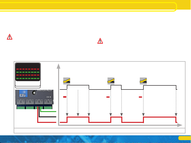
4.4.1. Pulse operation
If the output is configured for pulse operation, the output is swit-
ched on as soon as an appropriate command is received. At the
same time, a timer automatically turns off the output as soon as a
predetermined time (pulse time) saved in the decoder has elapsed,
even if the button (on the command station or control panel) has
been released beforehand. If the button is pressed longer than the
Operating modes
pre-determined pulse time, the output will still be switched off.
Limiting the switch-on time prevents accessories to blow.
Optionally, the output can also be slowly dimmed up and dimmed
down (so-called „zoom” for incandescent lamp simulation).
The pulse operation is the default setting of the SwitchPilot 3 and
is ideal for controlling solenoid turnout drives.
Some DCC command stations (e.g.: by Lenz) repeat the power
command in a fixed rhythm until the button is released. With each
power-on command received, the SwitchPilot 3 resets the stop-
watch. This is shown in Fig. 1.
Figure 1: Pulse operation
keyboard
1 2 3 4 5 6 7 8
9 10 11 12 13 14 15 16
time
on
off
1
RED
ON
1
RED
OFF
1
(RED
ON)
(Lenz)
Impulse-Time
1
RED
ON
1
RED
OFF
Impulse-Time
1
RED
ON
1
RED
OFF
Impulse-Time
7
4.4.2. Operating PECO turnout drives
The PECO mode corresponds to the afore mentioned pulse ope-
ration with the exception that to increase the peak current the
overcurrent protection of the output pair is switched off and the
pulse time is fixed to a relatively short time span. This short current
surge is used to optimally control the PECO drives.
Incorrect wiring or a short circuit at an output in PECO mode can
destroy the SwitchPilot 3 decoder!
4.4.3. K83 operation (momentary action mode)
In K83 mode, the output remains active until the button on the
command station or control panel is released. This operating
mode is suitable for turnout drives with end position shutdown
or for uncoupling tracks.
Optionally, the output can also be slowly dimmed up and dimmed
down (so-called „zoom” for incandescent lamp simulation).
K83 operation may cause problems with older DCC command sta-
tions, because they do not transmit the required „Off” command
(e.g.: older Lenz command stations).
Figure 2: K83 operation (momentary action mode)
keyboard
1 2 3 4 5 6 7 8
9 10 11 12 13 14 15 16
time
on
off
1
RED
ON
1
RED
OFF
1
(RED
ON)
(Lenz) 1
RED
ON
1
RED
OFF
1
RED
ON
1
RED
OFF
Operating modes

8
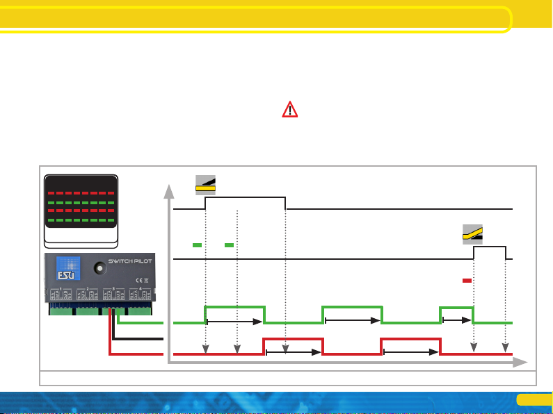
4.4.4. K84 Operation (Bistable continuous operation)
In K84 mode, the two outputs are alternately switched on and
off: When pressing the first button (red) on the command station,
the Output Out A is turned on. It remains active until pressing the
assigned button (green) activates the output Out B of the same
output group. Out A and Out B behave like a change-over switch.
Optionally, the output can also be slowly dimmed up and dimmed
down (so-called „zoom” for incandescent lamp simulation).
The K84 operation is well suited for lighting applications or two-
aspect daylight signals.
The logic of this mode of operation corresponds to the Märklin®
k84 decoder.
Figure 3: K84 operation (Bistable continuous operation)
keyboard
1 2 3 4 5 6 7 8
9 10 11 12 13 14 15 16
time
on
off
1
RED
ON
1
RED
OFF
1
(RED
ON)
(Lenz)
1
GREEN
ON
1
(GREEN
ON)
(Lenz)
1
GREEN
OFF
1
RED
ON
Operating modes
9
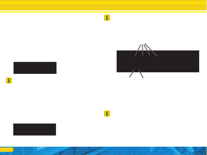
4.4.5. Alternate flasher mode
In this mode, the outputs Out A and Out B of an output pair are
switched on alternately with an adjustable flashing frequency. The
alternate flasher is started with the command „Straight/Green” of
the assigned button and stopped again with the command „Di-
verging/Red”.
Optionally, the output can also be slowly dimmed up and dimmed
down (so-called „zoom” for incandescent lamp simulation).
The alternating flasher operation is ideal for illuminating St.
Andrew´s crosses at level crossings.
4.4.6. Operating mode switch
With the decoder´s mode switch, you can quickly switch all output
pairs simultaneously to the „k83” or „k84” mode, regardless of
how they might be configured.
Only in the center position „USER” (default setting ex works) the
outputs will behave as programmed in the decoder configuration.
Any configured „zoom” effects are ignored when the mode
switch forces the decoder hard into k83 or k84 mode.
Figure 4: Alternate flasher mode
keyboard
1 2 3 4 5 6 7 8
9 10 11 12 13 14 15 16
time
on
off
1
RED
ON
1
RED
OFF
1
GREEN
ON
1
(GREEN
ON)
(Lenz)
1
GREEN
OFF
Flash-Time
Flash-Time
Flash-Time
Flash-Time
Stop
Operating modes
10
5. Connection to the digital system
We recommend that you first configure the SwitchPilot 3 decoder
completely and then install it on the layout.
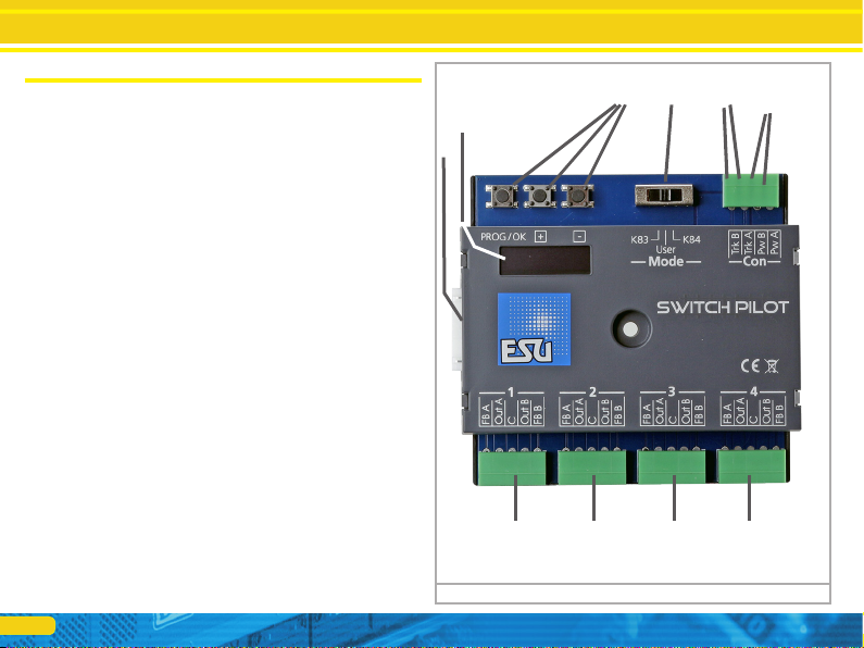
5.1. Terminals
Fig. 5 shows the SwitchPilot 3 with all terminals.
a) Turnouts, daylight signals, uncouplers and similar electric loads
shall be connected to the terminals labelled 1 to 4 for the out-
put pairs 1 to 4. The respective terminals FB A and FB B are
required for providing feedback from the turnout drive to the
SwitchPilot 3.
b) The power supply of the SwitchPilot 3 including all connected
loads is realized vie the Terminals Pw A and Pw B. You can eit-
her use the track voltage or use an external power supply. We
recommend an external power supply, particularly for larger
layouts, because then the energy for powering the drives does
not add to the load for the command station or booster.
c) Connect the Terminals Trk A and Trk B to the track output of
the command station (or booster) that controls the SwitchPilot
3.
d) As described in chapter 4.4.6., the outputs can be configured
simultaneously with the operating mode switch.
e) Input unit. The three buttons PROG/OK as well as (+) and (-)
serve to configure the decoder, as explained in chapter 6.
f) The display shows all settings of the decoder including turnout
address and status of the outputs. After a few seconds, the
screen saver displays the supply voltage.
g) Extension socket for the SwitchPilot Extension relay module.
Figure 5: Terminals of the SwitchPilot 3
Connection to the digital system
g)
f)
e) d) c) b)
a) a) a) a)
11
Connection to the digital system
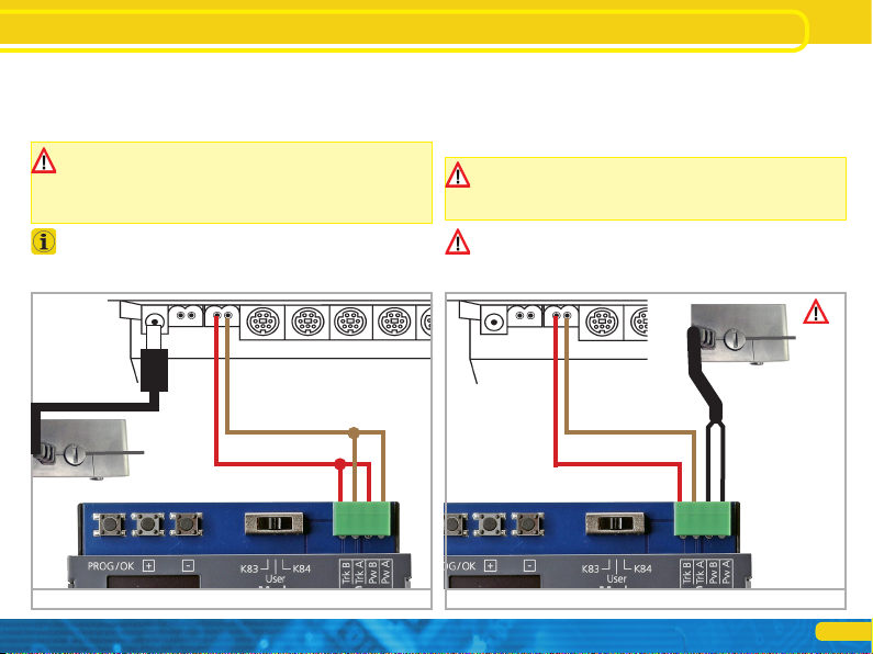
5.2. Power supply by the digital system
For smaller layouts with only a few electric loads turned on at the
same time, the SwitchPilot 3 can be supplied directly from the
command station or booster. The terminals Pw A and Pw B are
connected parallel to the terminals Trk A and Trk B.
If accessories (e.g.: Märklin® K track) do not switch at all or only
respond with little power, check the track voltage and increase
it, if necessary. The SwitchPilot 3 can display the supply voltage
as described in chapter 6.8.1. If the voltage cannot be increased,
please use an external power supply.
This wiring scheme must be used if you want to configure the
SwitchPilot 3 on the programming track of your command station.
For more information, see Chapter 9.
5.3. External power supply
For larger layouts with many electric loads, we recommend the
use of an external power supply. DC and AC power supplies are
suitable with the specifications described in chapter 4.2. We re-
commend the use of a stabilized DC power supply with at least
18V DC at least 3A output power (e.g.: ESU part number 50119).
For switching Märklin® K track drives a minimum of 18V is
required. Keep this in mind when choosing the transformer!
The SwitchPilot 3 can display the supply voltage as described
in chapter 6.8.1.
This type of wiring cannot be used for programming on the pro-
gramming track. In this case, a temporary connection must be
established as shown in chapter 5.2.
B 0
Main track exit
min. 18V
B 0
Main track exit
min. 18V
Stabilized DC
power supply
recommended
Figure 6: Supply from the digital system Figure 7: Separate (external) power supply
12
Wiring the outputs
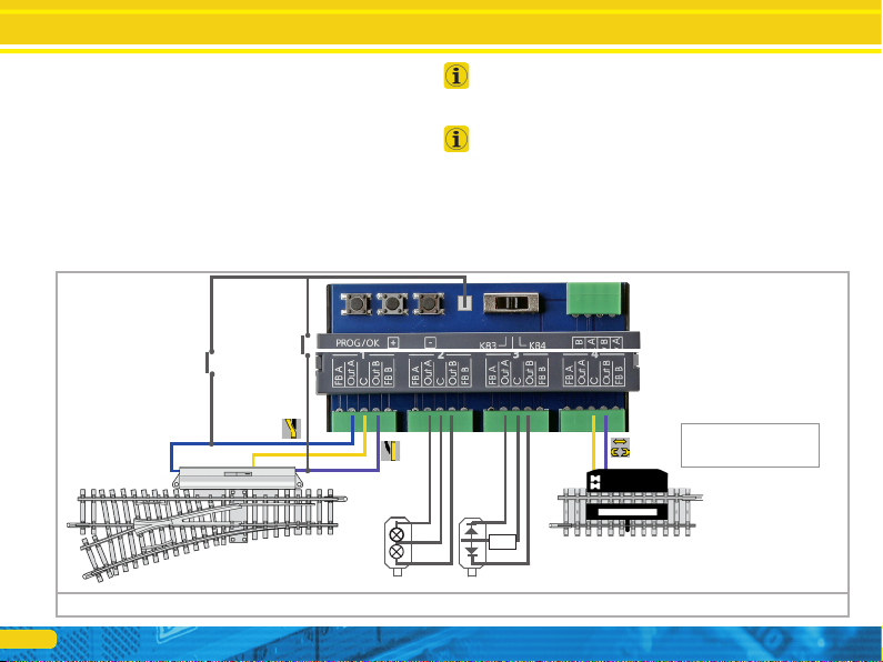
5.4. Wiring the outputs
5.4.1. Solenoid turnout drives
You may use any of the commercially available solenoid turnout
drives from the well-known manufacturers with the SwitchPilot 3.
Figure 8 shows the wiring of a turnout at output 1.
a) The common wire from the two coils is connected to terminal
C.
b) Terminal Out A is connected to the wire for the diverging route.
c) Terminal Out B is connected to the wire for the straight route.
Should the turnout not be aligned as you intended after pressing
the respective button on your command station respectively con-
trol panel (diverging and straight route are reversed), please swap
the wires at terminals Out A and Out B.
The power consumption of PECO switch drives is so high that the
PECO operating mode must be set.
5.4.2. Daylight signals with incandescent lamps or LEDs
If you are using daylight signals with incandescent lamps (bulbs)
or LEDs (light-emitting diodes), the corresponding output must be
configured in the K84 mode (Bistable continuous operation).
Incandescent lamps, as shown in Figure 8, Output 2, may be di-
rectly connected to the SwitchPilot 3.
Figure 8: Wiring the outputs
R
For uncouplers:
K83 operation (momentary
operation) to adjust.
Example for output 4:
OUTPUT 4
MODE :K83
Time :Permanent
Zoom :Disabled
Triggering also by
Button possible.

13
Wiring the outputs
If, on the other hand, signals or lighting with LEDs are used (as
shown in Figure 8, Output 3), a series resistor must be used to
limit the current. The resistance value depends to a large extent
on the type of LED used, so no precise statement is possible here.
Values between 1 kOhm and 10 kOhm are common. If in doubt,
start with a higher value.
The terminal C of the output is the „+” pole. Therefore, the catho-
de of the LED must be connected to the terminals Out A or Out B.
5.4.3. Uncoupling tracks
The momentary action mode is suitable for uncoupling tracks, as
the coil will be active only until the button is released. The wiring
is as shown in Fig. 8, Terminal 4. You can use either Terminal Out A
or Out B, depending on whether you want to activate the uncoup-
ler with the „diverging” or „straight” turnout button.
b)
or
a)
Figure 9: Connection of the turnout feedback
5.5. Wiring the feedback contacts
The SwitchPilot 3 can report the actual turnout status to the ESU
ECoS command station via RailCom®. For this purpose, however,
the turnout must have appropriate mechanical feedback contacts.
Figure 9 illustrates the scenario.
a) Connection of a turnout drive with limit stop contacts. Con-
nect terminals Out A to FB A and Out B to FB B.
b) Connection to drives with separate feedback contacts: Here
you wire the two feedback contacts to the terminals FB A and
FB B respectively, and the common wire of the feedback to
terminal C.
You will find more information on turnout feedback to the ESU
ECoS via RailCom® in chapter 11.
14
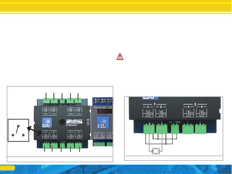
5.6. Connecting the SwitchPilot Extension
The SwitchPilot Extension module is docked sideways to the
SwitchPilot 3; press the extension module with the 8-pin plugs
against the SwitchPilot 3 until the retaining clips of the plugs snap
in. The internal electronics and relay coils of the SwitchPilot Exten-
sion module are powered by the SwitchPilot 3.
5.6.1. Relay outputs
Fig. 10 shows the connections:
a) The outputs 1 to 4 are connected to relay outputs A and B,
which are activated jointly (2x change-over contacts, bistable).
Each relay output corresponds to the corresponding transistor
output of the SwitchPilot 3. If the output Out A of the Switch-
Pilot 3 is active, the terminals Iand COM of the relay output
are also active. If the output Out B on the SwitchPilot 3 is
active, terminals II and COM are also active.
b) Terminals for ground and „U+” (rectified track voltage, sup-
plied by SwitchPilot 3) for powering DC turnout motors.
5.6.2. Motorized turnout drives
Motorized turnout drives can be controlled with the help of the
SwitchPilot Extension module. Reversing the operating voltage of
the electric motor changes the direction of rotation of the mo-
tor, thereby moving the turnout from one position (status) to the
other.
Use only turnout drives with limit stop contacts to prevent the
motor from burning through, because the relay outputs of the
SwitchPilot Extension module are continuously active.
The wiring of the motorized turnout drive is shown in Fig. 11.
Please note the maximum supply voltage values specified in the
instructions for your drive. The Extension module always delivers
the full voltage that is provided to the SwitchPilot 3.
Figure 10: SwitchPilot with mounted SwitchPilot Extension
a) a) b) a) a)
a) a) b) a) a)
III
Com
Figure 11: Motorized point machine with SwitchPilot Extension
M
Wiring the outputs

15
5.6.4. Turnout frog polarization
Mit dem SwitchPilot Exension Modul können sehr einfach Wei-
chen-Herzstücke polarisiert werden.
Wiring the outputs
5.6.3. LGB® Turnout drive
The wiring is as shown in Fig. 12. Unless reprogrammed, the mo-
tors are supplied with electricity for approx. 520 msec and are then
switched off to prevent overheating of the drive.
Figure 12: LGB®Turnout drive Figure 13: Polarization with SwitchPilot Extension

16
Each SwitchPilot 3 can be assigned such a 4-series group: this is
the so-called accessory address.
The accessory address is stored internally in CV 1 and CV 9. The
calculation of the turnout numbers from the values saved in the
two CVs is regulated in the RCN-213 standard.
The table in chapter 16 lists turnout numbers and corresponding
accessory addresses. Only the first 256 turnouts are available
when operating with Motorola® central units.
It is not possible to assign turnout numbers outside the group-of-4
limits to a SwitchPilot 3. For example. it would not be possible to
assign turnout numbers 4, 5, 6 and 7, as these go beyond the limit
of the accessory address groups. Please keep this in mind when
assigning turnout numbers.
Due to a weakness in the DCC standard prior to the creation of
the RCN-213, some command stations (especially ROCO® Multi-
maus or Z21) calculate the turnout numbers differently. In this case
please take note of chapter 6.3.
Configuration with OLED
6. Configuration with OLED
The programming of accessory decoders was usually very cum-
bersome in the past. CV programming with the help of the hand-
held throttle often failed due to the missing programming modes
(e.g.: only very few command stations and/or throttles respectively
central units support „POM for accessory decoders”) or forgotten
addresses of decoders installed on the layout. Even assigning the
decoder address presented many model railway enthusiasts with
major obstacles. Reading the currently assigned decoder address is
also quite cumbersome and causes a lot of displeasure.
To avoid such problems, the SwitchPilot 3 is the first accessory
decoder on the market working with an innovative operating con-
cept. It consists of an illuminated multi-line OLED display and a
3-button input unit. This allows programming all (!) settings of
the SwitchPilot 3 in plain text directly on the decoder, without the
need of external programming devices or cumbersome CV pro-
gramming. In addition, the display shows the currently assigned
turnout numbers at any time and can even accurately display the
supply voltage (respectively track voltage). A screen saver prevents
the OLED display from burning in.
6.1. Relationship between accessory addresses and turnout
numbers
For addressing the outputs of the SwitchPilot 3 decoder with the
command station, so-called turnout numbers must be assigned to
them. The number of turnout numbers is limited and depends on
the digital system:
Motorola®: Turnout numbers 0001 bis 0256
DCC: Turnout numbers 0001 bis 2048
(ROCO command stations 0001 to 2040).
The turnout numbers are arranged into four groups. The first
group comprises turnout numbers 1,2,3,4, the second group the
turnout numbers 5,6,7,8, the third group the turnout numbers
9,10,11,12, and so forth.

17
Assigning turnout numbers
6.1.1. Assigning turnout numbers
Ex works, the 4 double outputs of the SwitchPilot 3 respond to
turnout numbers 0001 to 0004. The turnout numbers can be ea-
sily changed directly on the SwitchPilot 3.
a) Check whether the display shows the screen saver (lettering
„SP” and the supply voltage):
b) In this case, press the „PROG/OK” button only (!) briefly. Now
the SwitchPilot 3 should display its current turnout numbers
directly in plain text:
c) Press the „PROG/OK” button. The turnout numbers should
now flash (inverse).
d) Press the button (+) or (-) to select the desired turnout num-
bers. The currently selected turnout numbers are displayed
flashing.
e) Press the „PROG/OK” button again to confirm the turnout
numbers. The indicator no longer flashes.
Finished! Without programming or cumbersome handling on the
handheld throttle or command station.
SP»17.3V
ADDRESS
Switch 1-4: 0001-0004
ADDRESS
Switch 1-4: 0001-0004
ADDRESS
Switch 1-4: 0009-0012
18
OUTPUT1
Mode : AltFlash
Time : 1720 ms
Zoom : Disabled
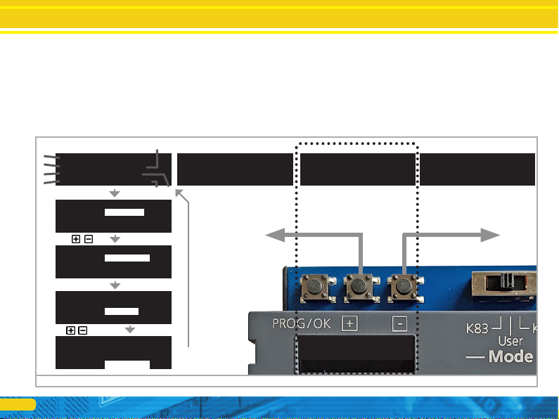
Introduction to the operating structure
6.2. Introduction to the operating structure
The configuration with the aid of the OLED display and the 3-but-
ton input unit enables you to set all parameters of the SwitchPilot
3 decoder.
All properties are arranged in so-called „panels”. A panel fills in
all four lines of the display. The first line displays the name of the
panel, and rows two to four display a maximum of three different
setting options. With the help of the „+” and „-” buttons you can
scroll between the individual panels.
a) Name of the panel
b) Name of setting option 1
c) Value of the setting option 1
d) Name of setting option 2
e) Value of the setting option 2
f) Name of the setting option 3
g) Value of the setting option 3
Figure 14: Control elements of the SwitchPilot 3
ADDRESS
Switch 1-4: 0001-0004
ADDRESS
Switch 1-4: 0001-0004
ADDRESS MODE
Mode : RCN-213
OUTPUT STATE
1 2 3 4
CMD ........
PHY ........
OUTPUT1
Mode : Impulse
Time : 520 ms
Zoom : Disabled
a)
c)
a)
b)
d)
f)
e)
g)
OUTPUT1
Mode : Impulse
Time : 520 ms
Zoom : Disabled
PROG/OK
OUTPUT1
Mode : AltFlash
Time : 1720 ms
Zoom : Disabled
PROG/OK
OUTPUT1
Mode : AltFlash
Time : 1720ms
Zoom : Disabled
PROG/OK
PROG/OK

19
•If you want to change a setting option of the currently selected
panel, press the PROG/OK button once. The setting option 1 of
the screen will now flash as a sign that it can be changed.
•For changing the respective setting
use the (+) and (-) buttons. Press the button until the display shows
the desired value. The decoder immediately applies the changes so
you can see immediately what is happening.
•Confirm your entry with PROG/OK. After that, the next setting
option will flash as a sign that it can now be changed.
If you do not want to change a setting option, but only want to
proceed to the next one, just press the PROG/OK button. Then
the current value is not changed.
•After you have changed the last of the three setting options re-
spectively confirmed them by pressing PROG/OK, nothing will
flash. You are now back in the display mode of the panel and can
now either make changes to other setting options of the panel
by pressing PROG/OK again or select another panel with the (+)
and (-) buttons.
For a list of all possible panels and their setting options, see Chap-
ter 15.
6.3. Address mode for ROCO® command stations
As already mentioned in Chapter 6.1, ROCO® command stations
(specially the multiMaus, but also the Z21 in the standard setting)
use a different computation method to calculate the turnout num-
bers from the accessory addresses. Set the decoder to “ROCO” to
ensure that the SwitchPilot 3 handles instructions from ROCO®
command stations correctly.
To do this, select „Mode” in the „ADDRESS MODE” panel, and
then select the calculation method „ROCO”.
Introduction to the operating structure
6.4. Configuring outputs
Each output can be configured individually. For this purpose, the
panels „OUTPUT 1” to „OUTPUT 4” are provided.
You can use the “Mode” option to set the desired output mode:
•“Pulse” configures pulse operation according to chapter 4.4.1.
•“PECO” configures PECO operating mode according to chapter
4.4.2.
•“K83” configures momentary action mode according to chapter
4.4.3.
•“K84” configures bistable continuous operation according to
chapter 4.4.4.
•“Alt Flash” configures the alternating flasher operation according
to chapter 4.4.5.
The meaning of the „Time” option depends on the selected out-
put mode:
•In pulse mode, it is determined here how long the output remains
switched on.
•In alternating flasher mode, you specify how fast the two outputs
should flash.
•In all other modes, „Time” has no meaning and cannot be chan-
ged respectively is set to „Permanent”.
OUTPUT1
Mode : Impulse
Time : 520 ms
Zoom : Disabled
OUTPUT2
Mode : PECO
Time : Permanent
Zoom : Disabled
OUTPUT3
Mode : K83
Time : Permanent
Zoom : Disabled
OUTPUT4
Mode : Alt-Flash
Time : 1170ms
Zoom : Enabled
20
Configuration
For particularly realistic fade-in and fade-out effects, you can add
a „zoom” function to each output, if so desired
•“Enabled” enables the pair to fade-in and fade-out
•“Disabled” turns off the fade-in and fade-out feature of the out-
put pair.
6.5. Setting fade-in and fade-out times
Here you can choose the time during which the outputs should
be dimmed up or down if the „Zoom” option is active at the cor-
responding output.
The time can be set from 0 msec to 4160 msec. The value „0
msec” turns off this feature for all outputs.
Do not choose exceedingly long durations. Especially in alternating
flasher mode, you should make sure that the flashing frequency is
selected significantly longer than the fade-in and fade-out times.
6.6. Status information
The SwitchPilot 3 can display extensive status and diagnostic in-
formation, which can be particularly helpful, especially for wiring
and troubleshooting.
6.6.1. Display software version & track voltage
The „Information” panel displays both the hardware („HW”) as
well as the software („SW”) version of the decoder. The supply
voltage („Voltage”) of the outputs is also displayed.
FADEIN & FADEOUT
Time : 260ms
If the SwitchPilot 3 is powered directly by the command station,
„Voltage” displays the digital track voltage, otherwise the voltage
of the connected power supply.
6.6.2. Displaying output states
Important information about the output state is provided by the
„Output State” panel
a) Number of the output
b) Output terminal „Out A” active
c) Output terminal „Out B” active
The PHY line indicates for each output 1 to 4 whether it is current-
ly active. As soon as the state changes (e.g.: when an alternate
flasher is active or because an output is switched off by the timer),
this is displayed in real time.
If the fade-in and fade-out feature is active for an output, the
output is immediately displayed as active, even if it is still fading-
in or -out.
The line CMD shows the latest command received for each output
1 to 4: A bar to the left directly below the number indicates that
the command „Red” was received from the command station, a
bar to the right of it indicates that the last command was „Green”.
If no valid command has been detected, only dots are displayed.
The SwitchPilot 3 saves the most recently detected commands so
that the last operating state is restored after a power interruption.
INFORMATION
HW : 3.0
FW : 3.0.9
Voltage : 17.3V
OUTPUT STATE
1 2 3 4
CMD .».»»..»
PHY .».....»
a)
b) c)
Table of contents
Other Esu Media Converter manuals

Esu
Esu LokPilot Standard User manual

Esu
Esu SwitchPilot User manual

Esu
Esu LokPilot V3.0 User manual

Esu
Esu LokPilot 52600 User manual

Esu
Esu L.Net converter User manual

Esu
Esu LokSound 5 DCC User manual

Esu
Esu LokSound micro V4.0 User manual

Esu
Esu SwitchPilot 3 User manual

Esu
Esu 51801 User manual

Esu
Esu SignalPilot 51840 User manual


