manuals.online logo
Brands
  1. Home
  2. •
  3. Brands
  4. •
  5. Inovonics
  6. •
  7. Transmitter
  8. •
  9. Inovonics EN1215WEOL User manual

Inovonics EN1215WEOL User manual

8/22/19 357-05043-02 Rev A © Inovonics, 2019 - www.inovonics.com
EN1215WEOL Door/Window with Wall
Tamper and EOL
Installation Instructions
1 Overview
The Inovonics EN1215WEOL door/window with wall tamper and
EOL has a built-in magnetic reed switch on the side, with a
magnet that supports a 5/8" inch gap. The magnetic reed switch
can be used with both ferrous and non-ferrous material. A 2.2K
ohm end of line resistor is included with the EN1215WEOL, and
is required for operation.
The EN1215WEOL includes a back tamper switch. The tamper
condition must be defined within the control panel as a trouble
condition when the system is disarmed, and as an alarm
condition when the system is armed.
The door/window with wall tamper and EOL is available in North
America, Australia and New Zealand; the radio frequency band
has been configured for the appropriate geographic area at the
factory.
Note: For UL installations, refer to the EN4216MR Installation
and Operation Manual, the EN4232MR Installation and
Operation Manual, or the EN7290 EchoStream Receiver/
Interface for Honeywell VISTA Panels Installation Instructions.
The switch contact must also be located in the same room as the
EN1215WEOL, and the EN1215WEOL must be installed in
accordance with UL 681 and ULc S302.
Note: The cable length from the switch contact must not to
exceed 10 feet.
Caution: The EN1215WEOL contains both a wired input and an
input activated by a reed switch and magnet. The reed switch
and magnet must be used unless the application specifically
supports both inputs as separate devices. Use of the wired input
is optional.
1.1 Inovonics Contact Information
If you have any problems with this procedure, contact Inovonics
Wireless technical services:
• E-mail: [email protected].
• Phone: (800) 782-2709.
1.2 EN1215WEOL Internal Components
Figure 1 Door/window with wall tamper and EOL internal
components
1.3 What’s In The Carton
• Two wall mount screws.
• Two wall mount anchors.
• Two selection jumpers.
• One 3.0V lithium battery.
• One housing closure screw.
• One magnet.
• One 2.2K ohm end of line resistor.
2 Installation and Startup
2.1 Installation Notes
• These products are designed to be installed and maintained
by professional security technicians.
• Products are intended for indoor use.
• Manually test all products weekly.
2.2 Battery Installation
1. Use your thumb to press the housing release tab on the
bottom of the transmitter; separate the housing.
2. Install the battery.
3. Press the reset button to initialize the transmitter.
4. Test the transmitter and ensure appropriate response.
2.3 Select Input Type and Wire Resistor
The N/O-N/C selection pins allow the choice of a normally open
or normally closed state for the contact circuit wired to the input
terminal.
The transmitter is shipped set for normally open, with a selection
jumper on the N/O selections pins.
Set for normally open operation:
1. Place a selection jumper on the selection pins to select
normally open.
2. Use 22 AWG wire to wire the 2.2K ohm resistor in parallel
with the N/0 contact per Figure 2. The distance from the
external contact to the EN1215WEOL must not exceed 10
feet (3 meters).
3. Press the reset button to complete configuration.
Figure 2 Wired for N/O operation
Set for normally closed operation:
1. Remove the selection jumper from the selection pins.
2. Use 22 AWG wire to wire the 2.2K ohm resistor in series with
the N/C contact per Figure 3. The distance from the external
contact to the EN1215WEOL must not exceed 10 feet (3
meters).
3. Press the reset button.
Figure 3 Wired for N/C operation
2.4 Register the EN1215WEOL
Transmitters must be registered with the system in order to be
monitored and supervised. When supervised, the transmitter will
send a check-in message to the receiver every three minutes.
Each transmitter has a unique factory-programmed identification
number.
Refer to the system receiver’s documentation for details on
registering the transmitter.
1. When prompted by the receiver to reset transmitter, press
the reset button.
2. Replace the cover.
3. Test the transmitter and ensure appropriate response.
For product and installation videos visit us at
www.inovonics.com/videos or use the QR
code below.
ACombined housing/wall tamper
switch
BN/O - N/C jumper
CInput terminal DReset button
EWall-mount screw holes FHousing closure screw hole
GReed switch
A
B
C
D
E
E
F
G
8/22/19 357-05043-02 Rev A © Inovonics, 2019 - www.inovonics.com
2.5 Mount the EN1215WEOL
1. Choose a mounting location which will allow the magnet to
be located parallel to the transmitter such that there is no
more than a 5/8” gap between it and the internal contact
magnetic reed switch.
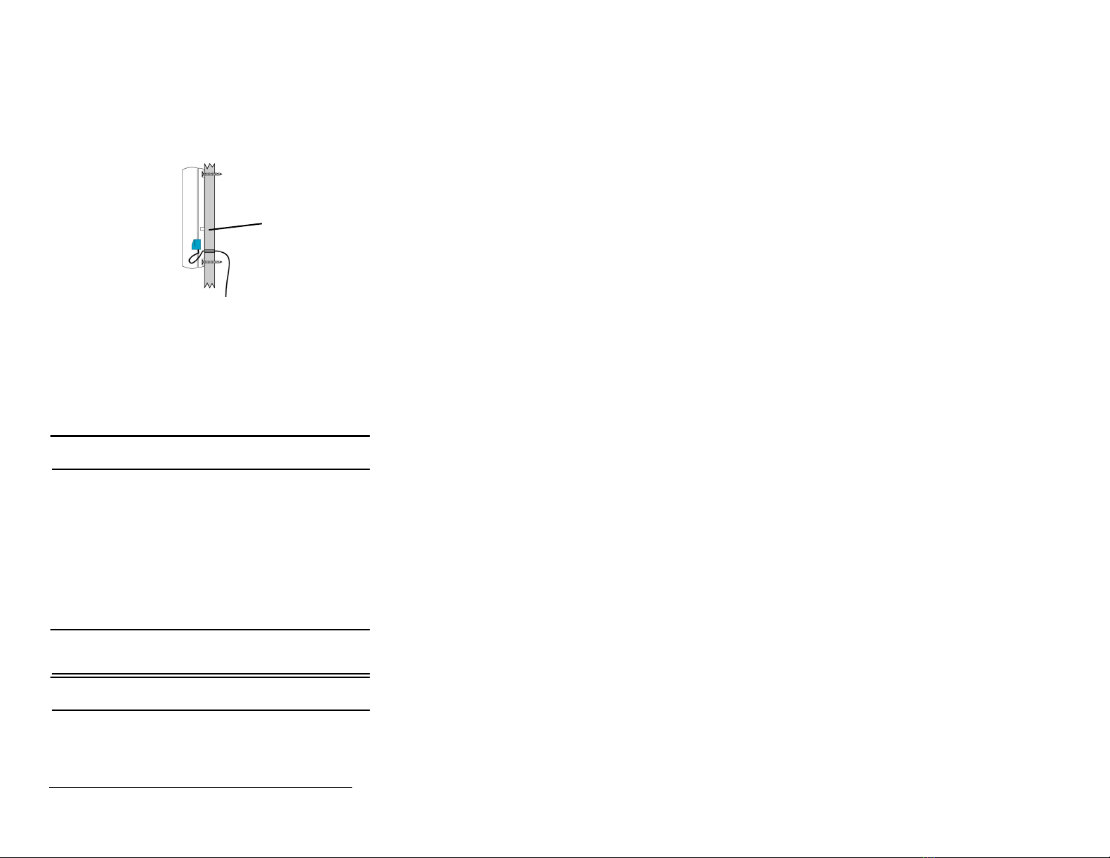
2. Route the external wiring through the wall, as shown in
Figure 4.
3. Mount the transmitter to the wall using the wall-mount screw
holes, ensuring the housing is flush against the wall and the
wall tamper switch is firmly depressed.
Figure 4 Mount the Transmitter to the Wall
4. Close the housing.
5. Secure the housing through the enclosed housing screw
hole. Accessing this screw on an active transmitter requires
opening the housing and removing the battery, causing a
tamper condition.
6. Mount the magnet so that it is parallel to the transmitter with
no more than a 5/8” inch gap between it and the internal
contact magnetic reed switch.
3 Specifications
Note: The 2.2K ohm resistor is required to operate the
EN1215WEOL.
External contacts: N/O or N/C.
Distance, external contact to EN1215WEOL: 10 feet (3 meters)
maximum.
Distance, magnet to internal contact magnetic reed switch: 5/8”.
Power requirement: 3VDC, 60 mA.
Typical battery life: 3-5 years.
Battery type (BAT604): Panasonic CR123A.
Operating environment: 0 to 60°C (32 to 140°F), 90% relative
humidity, noncondensing; 0 to 49°C (32 to 120°F) for UL
installations.
UL listings: UL 365, UL 634, ULC/ORD-C634-86, UL 1023, ULC/
ORD-C1023-74, UL 1076, UL 1610.
Compatible receiver: EN4204R, EN4216MR, EN4232MR,
EN7290.
Note: Inovonics supports recycling and reuse whenever
possible. Please recycle these parts using a certified electronics
recycler.
Note: Specifications and data are subject to change without
notice.
4 Television and Radio Interference
This equipment has been tested and found to comply with the
limits for a Class B digital device, pursuant to Part 15 of the FCC
Rules. These limits are designed to provide reasonable
protection against harmful interference in a residential
installation. This equipment generates, uses and can radiate
radio frequency energy and, if not installed and used in
accordance with the instructions, may cause harmful
interference to radio communications. However, there is no
guarantee that interference will not occur in a particular
installation. If this equipment does cause harmful interference to
radio or television reception, which can be determined by turning
the equipment off and on, the user is encouraged to try to correct
the interference by one or more of the following measures:
• Reorient or relocate the receiving antenna.
• Increase the separation between the equipment and
receiver.
• Connect the equipment into an outlet on a circuit different
from that to which the receiver is connected.
• Consult the dealer or an experienced radio/TV technician
for help.
5 FCC Part 15 and Innovation, Science and
Economic Development Canada (ISED)
Compliance
This device complies with part 15 of the FCC Rules, and ISED
license-exempt RSS standard(s). Operation is subject to the
following two conditions: (1) this device may not cause
interference, and (2) this device must accept any interference
that may cause undesired operation of the device.
Le présent appareil est conforme aux CNR Innovation, Sciences
et Développement économique Canada applicables aux
appareils radio exempts de licence. L'exploitation est autorisée
aux deux conditions suivantes: (1) l'appareil ne doit pas produire
de brouillage, et (2) l'utilisateur de l'appareil doit accepter tout
brouillage radioélectrique subi, même si le brouillage est
susceptible d'en compromettre le fonctionnement.
6 Radiation Exposure Limits
6.1 FCC
This equipment complies with FCC radiation exposure limits set
forth for an uncontrolled environment. In order to avoid the
possibility of exceeding the FCC radio frequency exposure limits,
human proximity to the antenna shall not be less than 20 cm
during normal operation and must not be co-located or operating
in conjunction with any other antenna or transmitter.
6.2 ISED
This equipment complies with ISED RSS-102 radiation exposure
limits set forth for an uncontrolled environment. This transmitter
must be installed to provide a separation distance of at least 20
cm from all persons and must not be co-located or operating in
conjunction with any other antenna or transmitter.
Cet équipement est conforme avec ISED RSS-102 des limites
d'exposition aux rayonnements définies pour un environnement
non contrôlé. Cet émetteur doit être installé à au moins 20 cm de
toute personne et ne doit pas être colocalisé ou fonctionner en
association avec une autre antenne ou émetteur.
Wall
Tamper

Other Inovonics Transmitter manuals

Inovonics EN1238D User manual

Inovonics

Inovonics EN1238D User manual

Inovonics EchoStream EN1242 User manual

Inovonics

Inovonics EchoStream EN1242 User manual

Inovonics EN1722 User manual

Inovonics

Inovonics EN1722 User manual

Inovonics EN1236D User manual

Inovonics

Inovonics EN1236D User manual

Inovonics FA214 User manual

Inovonics

Inovonics FA214 User manual

Inovonics EE1216 User manual

Inovonics

Inovonics EE1216 User manual

Inovonics EN1223S EchoStream User manual

Inovonics

Inovonics EN1223S EchoStream User manual

Inovonics EN1212 User manual

Inovonics

Inovonics EN1212 User manual

Inovonics FA200 User manual

Inovonics

Inovonics FA200 User manual

Inovonics EchoStream EN1215D-15 User manual

Inovonics

Inovonics EchoStream EN1215D-15 User manual

Inovonics EchoStream EN1235SF User manual

Inovonics

Inovonics EchoStream EN1235SF User manual

Inovonics EchoStream EN1215EOL User manual

Inovonics

Inovonics EchoStream EN1215EOL User manual

Inovonics EchoStream Select ES1223D User manual

Inovonics

Inovonics EchoStream Select ES1223D User manual

Inovonics EN1501 User manual

Inovonics

Inovonics EN1501 User manual

Inovonics ES1501 EchoStream TapWatch User manual

Inovonics

Inovonics ES1501 EchoStream TapWatch User manual

Inovonics EN1210 Series User manual

Inovonics

Inovonics EN1210 Series User manual

Inovonics EchoStream EN1210W User manual

Inovonics

Inovonics EchoStream EN1210W User manual

Inovonics ShatterPro EE1247 Owner's manual

Inovonics

Inovonics ShatterPro EE1247 Owner's manual

Inovonics EchoStream EN1233S/D User manual

Inovonics

Inovonics EchoStream EN1233S/D User manual

Inovonics 3B6OT9ESL User manual

Inovonics

Inovonics 3B6OT9ESL User manual

Inovonics EchoStream TapWatch EN1501 User manual

Inovonics

Inovonics EchoStream TapWatch EN1501 User manual

Inovonics EchoStream EN1215WEOL User manual

Inovonics

Inovonics EchoStream EN1215WEOL User manual

Inovonics EN1224 User manual

Inovonics

Inovonics EN1224 User manual

Inovonics EchoStream EN1212 User manual

Inovonics

Inovonics EchoStream EN1212 User manual

Popular Transmitter manuals by other brands

AMG AMG5913-2A9 instruction manual

AMG

AMG AMG5913-2A9 instruction manual

RadioMaster TX16S manual

RadioMaster

RadioMaster TX16S manual

Spectron IT-12-Exd operating manual

Spectron

Spectron IT-12-Exd operating manual

newins NT 3400P Series quick start guide

newins

newins NT 3400P Series quick start guide

GF Signet 8850-3 manual

GF

GF Signet 8850-3 manual

Dataradio Paragon-III user manual

Dataradio

Dataradio Paragon-III user manual

Audiovox Pursuit 095BPr Programming guide

Audiovox

Audiovox Pursuit 095BPr Programming guide

Kensington LiquidFM K33408US Instruction guide

Kensington

Kensington LiquidFM K33408US Instruction guide

Festo SDAT-MHS SA Series Brief Instruction

Festo

Festo SDAT-MHS SA Series Brief Instruction

ActionTec ScreenBeam SBT100U user guide

ActionTec

ActionTec ScreenBeam SBT100U user guide

Cygnett CY-3-PA2 Setup instructions

Cygnett

Cygnett CY-3-PA2 Setup instructions

DLO TransDock Deluxe manual

DLO

DLO TransDock Deluxe manual

Setra Systems SRH300 operating instructions

Setra Systems

Setra Systems SRH300 operating instructions

Lectrosonics HHa quick start guide

Lectrosonics

Lectrosonics HHa quick start guide

BT Redcare Essential installation guide

BT Redcare

BT Redcare Essential installation guide

AFi MT-3340-12VDC instruction manual

AFi

AFi MT-3340-12VDC instruction manual

Lightware DVI-OPT-TX110 quick start guide

Lightware

Lightware DVI-OPT-TX110 quick start guide

Visonic mct-241 user guide

Visonic

Visonic mct-241 user guide

manuals.online logo
manuals.online logoBrands
  • About & Mission
  • Contact us
  • Privacy Policy
  • Terms and Conditions

Copyright 2025 Manuals.Online. All Rights Reserved.