Nautel XR12 User manual

Document: XR12-PREINST
Issue: 0.17 2005-08-31
Status: Preliminary
XR12 Transmitter
Pre-installation Manual

Nautel Limited
10089 Peggy’s Cove Road
Hackett’s Cove, NS Canada B3Z 3J4
Phone: +1.902.823.2233
Fax: +1.902.823.3183
Nautel Maine Inc.
201 Target Industrial Circle
Bangor, Maine USA 04401
Phone: (207) 947-8200
Fax: (207) 947-3693
Email: suppor[email protected]
Web: www.nautel.com
The comparisons and other information provided in this document have
been prepared in good faith based on publicly available information. The
reader is encouraged to consult the respective manufacturer's most recent
published data for verification.
© Copyright 2005 NAUTEL. All rights reserved.

XR12 Transmitter Pre-installation Manual Table of contents
Page i
Contents
About this manual v
About safety vii
Description 1-1
Capabilities 1-1
Options 1-2
Pre-installation tasks 2-1
Preparing for installation 2-1
Selecting a location for the transmitter 2-3
Installing an antenna feedline 2-3
Physical requirements 3-1
Dimensions 3-1
Clearances 3-2
Weight 3-8
Cooling requirements 4-1
Air flow in the transmitter 4-1
Cooling 4-3
Heating 4-4
Electrical requirements 5-1
Electrical power 5-1
Station reference ground 5-4

XR12 Transmitter Pre-installation Manual
Page ii Issue 0.17 2005-08-31
Control and monitoring 6-1
Controls 6-1
Alarms 6-1
Remote control circuits and alarms 6-3
Remote performance monitoring 6-8
Other considerations 7-1
External RF drive source 7-1
External 10 MHz frequency reference 7-2
RF output requirements 8-1
Antenna feed cable 8-1
Antenna system 8-3
Parts and tools 9-1
Parts supplied by Nautel 9-1
Parts not supplied by Nautel 9-2
Tools for installation 9-3
Accessories 10-1
AC line surge protection 10-1
Automatic antenna transfer control unit 10-2
RF contactor 10-2
Automatic switching system 10-3
Dynamic carrier control unit 10-3
Spares 10-4
Extended warranty plans 10-5
Documentation 10-6

XR12 Transmitter Pre-installation Manual
Issue 0.17 2005-08-31 Page iii
XR series on-site or factory training 10-6
Pre-installation assistance 11-1
Pre-installation consulting 11-1
Installation and commissioning service 11-1
Online documentation 11-4
Onsite support 11-4
Training 11-4
Extended warranties 11-5
List of terms 12-1
Index 13-1

XR12 Transmitter Pre-installation Manual
Page iv Issue 0.17 2005-08-31

XR12 Transmitter Pre-installation Manual
Issue 0.17 2005-08-31 Page v
About this manual
This manual provides information about preparing for the delivery and installation of a XR12
transmitter. This manual is intended for use by field technicians, site managers, and installation
planners.
Using this manual
Read the task list provided in Section 2, “Pre-installation tasks” on page 2-1. The task list describes
the preparations you must make prior to receiving and installing the XR12 transmitter.
Later sections of this manual provide reference information regarding physical, cooling, electrical and
antenna requirements.
Features of this manual
This manual contains a number of useful features:
Online
• Click on blue text to jump to a related section or get additional information (for example, to
view a definition of a term).
• To find keywords, use Find in Acrobat Reader’s Edit menu.
• To quickly find a specific section, click the section in the Bookmark list.
Printed
• To find keywords, go to the Index at the end of the manual.
• To find a specific term, go to Section 12, “List of terms” on page 12-1.

XR12 Transmitter Pre-installation Manual
Page vi Issue 0.17 2005-08-31
XR12 transmitter manuals
The XR12 documentation suite includes the following documents:
XR12 Pre-installation Manual, XR12-PREINST. The Pre-installation Manual provides
instructions and reference information needed when planning and preparing for the installation of an
XR12 transmitter.
Nautel Site Protection Manual. The Site Protection Manual provides detailed information
about protecting your site from lightning-related hazards.
XR12 Installation Manual, XR12-INST. The Installation Manual provides instructions and
reference information needed when installing an XR12 transmitter.
XR12 Operating and Maintenance Manual, XR12-OPS-MAINT. The Operating and
Maintenance Manual provides instructions for operating, maintaining and troubleshooting an XR12
transmitter. It also provides reference information needed when performing diagnostic procedures.
XR12 Technical Reference Manual, XR12-REF. The Technical Reference Manual provides
detailed technical information about the XR12 transmitter.
Online resources
The Nautel website provides useful resources to keep you up to date on your XR12 transmitter.
Nautel User Group (NUG)
The website includes a special section that customers can log into in order to access the Nautel
customer newsletter, product manuals, frequently asked questions (FAQ), information sheets, and
information about field upgrades.
Online documentation
The website’s NUG section provides online access to all the documentation for your XR12
transmitter. Documentation is provided in Acrobat (PDF) format. You can use the documentation
online or print the sections that you need.

XR12 Transmitter Pre-installation Manual
Issue 0.17 2005-08-31 Page vii
About safety
All Nautel transmitters are designed to meet the requirements of IEC215, Safety Requirements for Radio
Transmitters. Sequenced key interlocks are offered as an option for those customers that require them.
The philosophy of IEC215 is that the removal of any cover or panel that can only be opened using a
tool is a maintenance activity, and that any person performing a maintenance activity is expected to be
trained for that activity. Under IEC215, it is assumed that trained personnel will be knowledgeable
and will take precautions such as removing all power to the transmitter before accessing its
components.
Electrical hazards
To remove power from the transmitter, switch off and lock out the three-phase power and then wait
10 minutes for the capacitor bank to discharge. There are several ultra-brite LEDs that glow inside
the cabinet to remind anyone who has not turned off the power that the system is live and that there
is serious danger.
Mount the transmitter disconnect close to the transmitter so that it can be reached quickly in an
emergency. Clearly label the disconnect.
After turning off the power, always perform a measurement to confirm that the power is off before
touching anything within the transmitter. If the wrong breaker was opened, the equipment will be
live.
Use only a non-contact voltage probe or a safety voltmeter (available from vendors such as Fluke,
Ideal, and Teagam).
WARNING: It is not enough to push the front panel button that
removes RF power. The power line is still connected and the three
phase rectifier and the large capacitor bank is still charged and is
LETHAL. Even when the three phase power is switched off and "locked
out," the capacitor bank is still charged and requires 10 minutes to
completely discharge.
WARNING: Do not use an ordinary DVM to check for voltage, since it
may have been left inadvertently on the AMP range, triggering a short
and an arc blast that could result in severe burns and even death.

XR12 Transmitter Pre-installation Manual
Page viii Issue 0.17 2005-08-31
Use a proper lockout procedure to ensure that another worker cannot accidentally reapply power
while you are performing maintenance on any part of the transmitter or site.
Lightning hazards
Before opening the transmitter and touching internal parts, remove and solidly ground the antenna
connection.
RF hazards
A serious RF hazard and very high voltages exist in the vicinity of the antenna and its networks
during normal operations.
Other hazards
Ensure that appropriate fire alarms and fire extinguishers are available. Extinguishers must be suitable
for use on electrical fires.
Many other site safety risks exist. It is beyond the scope of this manual to identify all the risks and
procedures.
WARNING: It is not enough to ground the antenna terminal with the
antenna still connected. Even a small impedance in the ground strap
will result in lethal voltages during a lightning strike.

XR12 Transmitter Pre-installation Manual Description
Issue 0.17 2005-08-31 Page 1-1
Section 1: Description
This section provides a detailed description of the XR12 transmitter. This section includes the
following topics:
•Capabilities
•Options - see page 1-2
Capabilities
Power
The XR12 Transmitter is capable of RF outputs of 1 - 10 kW.
The operator can vary the power continuously or switch to preset power levels using the XR12’s
graphic user interface (GUI). Presets store the power level, active exciter, and power scheduler status
on a time-of-day and date basis. The operator can configure exciters on a preset for a specific
operating mode (for example, exciter A for conventional AM, and exciter B for IBOC). The power
output can also be scheduled to correspond with authorized daytime power levels.
Modulation
The XR12 lets you use a number of modulation schemes, including:
• double sideband amplitude modulation (AM)
• IBOC (requires additional equipment)
• DRM (requires additional equipment)
Duty cycle
The XR12 will operate at nominal power with a 100% duty cycle (continuously) on an indefinite
basis.
Antenna tolerance
The XR12 will operate at full power even with a VSWR of 1.5:1. A higher VSWR results in a
protective fallback of output power. The greater the VSWR, the greater the reduction in RF power.
(To maintain the quality of digital broadcasts, a maximum VSWR of 1.4:1 is acceptable.)

XR12 Transmitter Pre-installation Manual Description
Page 1-2 Issue 0.17 2005-08-31
The XR12 will not fail or completely shut down, regardless of antenna or feedline failure.
Remote control and monitoring
The XR12’s remote control and monitoring options allow you to run a multiconductor signaling
cable from the transmitter to a remote control board. This option lets you monitor all key parameters
of transmitter operation, and control common functions such as power output and exciter selection.
For detailed information about remote control and monitoring, see Section 6, “Control and
monitoring” on page 6-1.
Redundancy
The XR12 features redundancy in all key systems:
• RF power modules
• Exciters
• Modulators
• Cooling fans
AC power
The XR12’s variable power transformer can be set to use a range of input voltages and power
frequencies.
Options
DCC
The XR12 supports Dynamic Carrier Control (DCC) as an optional external module. DCC reduces
the power of the carrier when the sideband power drops below a threshold (that is, when there are
periods of silence in the program content). This reduces overall power consumption.
IBOC
The XR12 supports IBOC digital radio as a modulation option. The external IBOC signal source
provides a signal to the XR12 exciter.

XR12 Transmitter Pre-installation Manual Description
Issue 0.17 2005-08-31 Page 1-3
DRM
The XR12 supports Digital Radio Mondiale (DRM) radio as a modulation option. The external DRM
signal source provides a signal to the XR12 exciter.
Safety interlocks
Optional safety interlocks present unsafe access to the transmitter, unless the ac power has been
disconnected.
This section provides a description of how the XR12 transmitter operates. For detailed technical
descriptions, schematics and mechanical drawings, refer to the XR12 Reference Manual.

XR12 Transmitter Pre-installation Manual Description
Page 1-4 Issue 0.17 2005-08-31

XR12 Transmitter Pre-installation Manual Pre-installation tasks
Issue 0.17 2005-08-31 Page 2-1
Section 2: Pre-installation tasks
This section provides a list of tasks that you must perform prior to delivery and installation of the
XR12 transmitter.
Preparing for installation
To prepare for installation of an XR12 transmitter, perform the following tasks:
1. Ensure that the correct transmitter configuration is ordered. Check the AC power
requirements, preset frequency, IBOC option, and other options.
2. Select a location for the transmitter in the transmitter room. For detailed information, see
“Selecting a location for the transmitter” on page 2-3.
3. Determine whether additional heating, ventilating or cooling capacity is needed at the site.
Identify any special requirements regarding air flow around the cabinet (for example, ducting
hot air away from the cabinet, or bringing in external cooling air). For detailed information
about temperature requirements, see Section 4, “Cooling requirements” on page 4-1.
4. If this is an upgrade or replacement transmitter (that is, if the site is already set up for a
transmitter), go to Step 9. (If you are upgrading a site, verify the feedline, the lightning
protection systems, and the AC power service. Refer to the Nautel Site Protection Manual.)
5. Install AC power service into the planned location of the transmitter, and select a location
for an AC power disconnect near the transmitter location. For detailed information, see
“Electrical power” on page 5-1.
Be aware of lightning protection issues when installing AC power. Lightning protection is
essential to protect both personnel and equipment at your site. Refer to the Nautel Site
Protection Manual.
6. Install lightning protection on the antenna tower. Refer to the Nautel Site Protection Manual.
WARNING: FAILURE TO COMPLY WITH RECOMMENDATIONS MAY VOID
YOUR MANUFACTURER’S WARRANTY. FOR MORE INFORMATION, REVIEW
YOUR WARRANTY DOCUMENTS.

XR12 Transmitter Pre-installation Manual Pre-installation tasks
Page 2-2 Issue 0.17 2005-08-31
7. Place a work area with a clear table surface near the transmitter location. Provide electrostatic
protection measures in the work area.
8. Order any accessories or optional equipment that you may need. See Section 10,
“Accessories” on page 10-1.
9. Terminate the transmitter end of the RF feedline with the appropriate mating connector.
Unless otherwise specified in contract documents, the transmitter will accept a 1-5/8 inch
EIA flange connector.
10. If the transmitter will be used to broadcast IBOC, perform a full impedance sweep of the
antenna system. See “Antenna system” on page 8-3.
11. Arrange manpower or lifting equipment to move and assemble the transmitter. You may
want to use a forklift to move either the transmitter or its power transformer into place for
installation. For information about component weight, see “Weight” on page 3-8.
12. Implement a safety interlock, if required.
13. If you are going to use an external RF drive, ensure that the drive meets required
specifications. See “External RF drive source” on page 7-1.
14. If you are going to use an external frequency reference, ensure that the reference source
meets required specifications. See “Installing an external RF drive source” on page 7-2.
15. Prepare to integrate the XR12 transmitter into your station control circuitry, if required. See
Section 6, “Control and monitoring” on page 6-1.
16. Train your station technicians and operators on the use and maintenance of the XR12
transmitter. For a list of available technical and user documents, see “XR12 transmitter
manuals” in the About this manual section at the beginning of this document. For information
about Nautel training courses, go to the Nautel website at http://www.nautel.com/support/
training/schedule/.

XR12 Transmitter Pre-installation Manual Pre-installation tasks
Issue 0.17 2005-08-31 Page 2-3
Selecting a location for the transmitter
To ensure that the desired location for the XR12 transmitter is suitable, perform the following tasks:
1. Ensure that the floor area where the transmitter will be located is able to support the weight
of the transmitter system.
The total weight of the assembled transmitter, once installed, is 329 kg (725 lb.).
2. Measure the space to ensure that the transmitter will fit. See “Physical requirements” on
page 3-1.
3. Ensure that transmitter room doors and the pathway of access from the receiving dock or
building exterior to the installation location are large enough to accommodate the
transmitter.
Installing an antenna feedline
When installing an antenna feedline for the XR12 transmitter, perform the following tasks:
1. Ensure that the RF feedline that will connect the transmitter and the antenna system has a
suitably rated coaxial cable.
2. Connect the shield of the antenna feedline coaxial cable directly to the station reference
ground where it enters the building. For more information about the station reference
ground, see “Station reference ground” on page 5-4.
3. Install lightning protection devices. For more information about lightning protection, refer
to the Nautel Site Protection Manual.
4. Pass the center conductor and the shield of the feedline cable through a ferrite toroid that is
positioned between the shield ground at the building entrance and the shield termination at
the transmitter. (The ferrite toroid is included in the ancillary kit, which is provided by
Nautel with the transmitter.)

XR12 Transmitter Pre-installation Manual Pre-installation tasks
Page 2-4 Issue 0.17 2005-08-31

XR12 Transmitter Pre-installation Manual Physical requirements
Issue 0.17 2005-08-31 Page 3-1
Section 3: Physical requirements
This section provides physical specifications for the XR12 transmitter and its components, and lists
physical site requirements. This section includes the following topics:
•Dimensions
•Clearances - see page 3-2
•Weight - see page 3-8
Dimensions
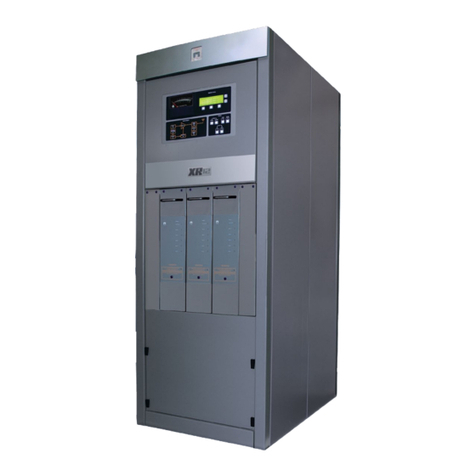
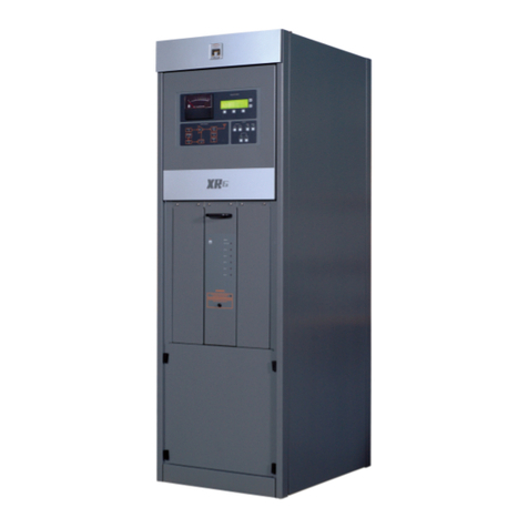
The XR12 transmitter cabinet has the following dimensions:
• Height: 184 cm (72.5 inches)
• Width: 72.4 cm (28.5 inches)
• Depth: 104 cm (41.0 inches)
Figure 3.1: XR12 transmitter

XR12 Transmitter Pre-installation Manual Physical requirements
Page 3-2 Issue 0.17 2005-08-31
Clearances
Required minimum clearances are 1.3 m (4.0 feet) at the front of the transmitter, and 2.0 m (6.0 feet)
at the rear of the transmitter. (The clearance at the rear of the transmitter is required to allow
installation of the power transformer. Less clearance may be acceptable if special arrangements are
made to install the transformer.) No clearance is required on either side of the transmitter.
Check the clearance to ensure that you will be able to open all doors and access panels. The front
control panel is hinged on the left (when looking at the front of the transmitter).
Also consider access to the rear of the transmitter during transformer installation and servicing, and
access to the front of the transmitter during power module replacement. You must allow space to
open the front panel and slide out any of the power modules. These modules slide straight in and out
of the shelf unit in the front of the transmitter.
Internal fans pull cooling air through air filters in the upper rear panel. The cooling air exhausts as a
low velocity stream through openings on top of the transmitter.
Other manuals for XR12
3
Table of contents
Other Nautel Transmitter manuals

Nautel
Nautel NX15 User manual
Nautel
Nautel NX400 User manual

Nautel
Nautel NX200 User manual

Nautel
Nautel NX50 User manual

Nautel
Nautel NX50 User manual

Nautel
Nautel NV20LT User manual

Nautel
Nautel VS2.5 Programming manual

Nautel
Nautel NX100 User manual

Nautel
Nautel GV60 Programming manual

Nautel
Nautel GV30N Programming manual

Nautel
Nautel NV5 Programming manual

Nautel
Nautel NV Series Technical manual

Nautel
Nautel VS1 User manual

Nautel
Nautel J1000 Operating instructions

Nautel
Nautel VS1 User manual

Nautel
Nautel GV40 Programming manual

Nautel
Nautel NV7.5 User manual

Nautel
Nautel VS300 User manual
Nautel
Nautel VS2.5 Programming manual
Nautel
Nautel VX150 User manual