Biamp 801I User manual

TM
801i
Mic/Line Mixer
Operation Manual
Biamp Systems, 10074 S.W. Arctic Drive, Beaverton, Oregon 97005 U.S.A. (503) 641-7287 www.biamp.com
an affiliate of Rauland Borg Corp.

print update
October 18, 2004

1
801
TABLE OF CONTENTS
Front Panel
Rear Panel
Options
Specifications & Block Diagram
Warranty
pg. 2
pg. 3
pgs. 4 & 5
pg. 6
INTRODUCTION
The 801i is a single rack-space mixer, with eight mic/line inputs and one
auxiliary line input. Each mic/line channel uses a differentially balanced,
discrete transistor preamplifier for low noise and low distortion performance.
Special features, including a limiter and remote level control, make the 801i
extremely versatile. The 801i mixer is dependable, easy to install, simple to
operate, and carries a five-year warranty.
801i features include:
♦eight differential balanced mic/line inputs & one aux line input
♦discrete transistor mic/line preamps for low noise & distortion
♦optional mic/line input isolation transformers (user installed)
♦+24 volt phantom power selectable on each mic/line input
♦aux input switch selectable for balanced or stereo summing
♦aux input 'auto-ducking' switch selectable on channels 1~8
♦front panel trim and rear panel pad switch on each channel
♦+10dB 'peak' LED indicator on each channel for easy set-up
♦high-pass 'rumble' filter switch selectable on each channel
♦mic/line & aux inputs on plug-in barrier strip connectors
♦unbalanced direct output terminal on each input channel
♦balanced main output on plug-in barrier strip connector
♦main output limiter with threshold control and LED indicator
♦main out Bass & Treble control with rear panel bypass switch
♦-20dB signal present & power LED indicators at main output
♦channel 1 automatic override assignable on other channels
♦optional remote control of main out via external level control
♦optional main output isolation transformer (user installed)
♦stack in & slave switch to add inputs by linking multiple units
♦covered by Biamp Systems' five-year warranty
♦marked and UL / C-UL listed power source

2
FRONT PANEL
801i
aux bass treble
threshold
–20 limit on
master1
+10
trim
2
+10
trim
3
+10
trim
4
+10
trim
5
+10
trim
6
+10
trim
7
+10
trim
8
+10
trim
+10
+10 Indicator (Channels 1~8 & Aux):These red LEDs will light
whenever channel signal levels reach +10dB (8dB below clipping).
Use this feature to aid in adjusting the Trim controls (see below).
Trim (Channels 1~8): These screw-driver adjustable controls set
the channel gain (0~60dB) to compensate for different input signal
levels. For best performance, adjust these controls so the channel
+10 indicators flash only on occasional peaks. If input signal
exceeds the normal operating range of the Trim control, assign the
rear panel Pad switch (see DIP switches on next page).
Level (Channels 1~8 & Aux):These controls adjust the amount of
signal sent from the individual input channels to the mixer output
section. Optimum Level settings are near the 12 o'clock position
(unity gain).
Bass: This control provides low-frequency tonal adjustment
(±10dB @ 100Hz) for signals at Main Patch & Main Output.
Treble: This control provides high-frequency tonal adjustment
(±10dB @ 10kHz) for signals at Main Patch & Main Output.
-20 Indicator: This red LED will light whenever signal levels reach
-20dB (signal present) at Main Output.
Master: This control adjusts the level of overall signal sent to
Main Output. Optimum Master settings are near the 12 o’clock
position (unity gain) or below.
Threshold: A limiter is provided at Main Output to help eliminate
unwanted peaks in signal level. This screw-driver adjustable
control sets the level at which the limiter will be activated. For
most applications, set Threshold so the limiter is activated only by
occasional peaks. Counter-clockwise adjustment lowers
Threshold, increasing the amount of limiting. Clockwise
adjustment raises Threshold, decreasing the amount of limiting.
Threshold is factory set fully clockwise, effectively removing the
limiter from operation.
Limit: This red LED will light whenever signal levels exceed the
threshold, thereby activating the limiter.
On Indicator: When the power transformer is plugged in, and AC
power is applied to the 801i, the red On indicator remains lit.

3
REAR PANEL
ON
pad
priority
phantom
duck aux
hp filter
ON
pad
priority
phantom
duck aux
hp filter
ON
pad
priority
phantom
duck aux
hp filter
ON
pad
priority
phantom
duck aux
hp filter
ON
pad
priority
phantom
duck aux
hp filter
ON
pad
priority
phantom
duck aux
hp filter
ON
pad
priority
phantom
duck aux
hp filter
ON
pad
priority
phantom
duck aux
hp filter
ON
slave
tone out
override
remote
ON
pad
priority
sum
hp filter
15 watts
class 2 wiring
50/60 Hz
~
27V
BIAMP SYSTEMS
an affiliate of Rauland Borg Corp.
main out stack in remote
vL
cR
MADE IN U.S.A.
channel 8
input
d. out
channel 7
input
d. out
channel 6
input
d. out
channel 5
input
d. out
channel 4
input
d. out
channel 3
input
d. out
channel 2
input
d. out
channel 1
input
d. out
aux
input
d. out
801i
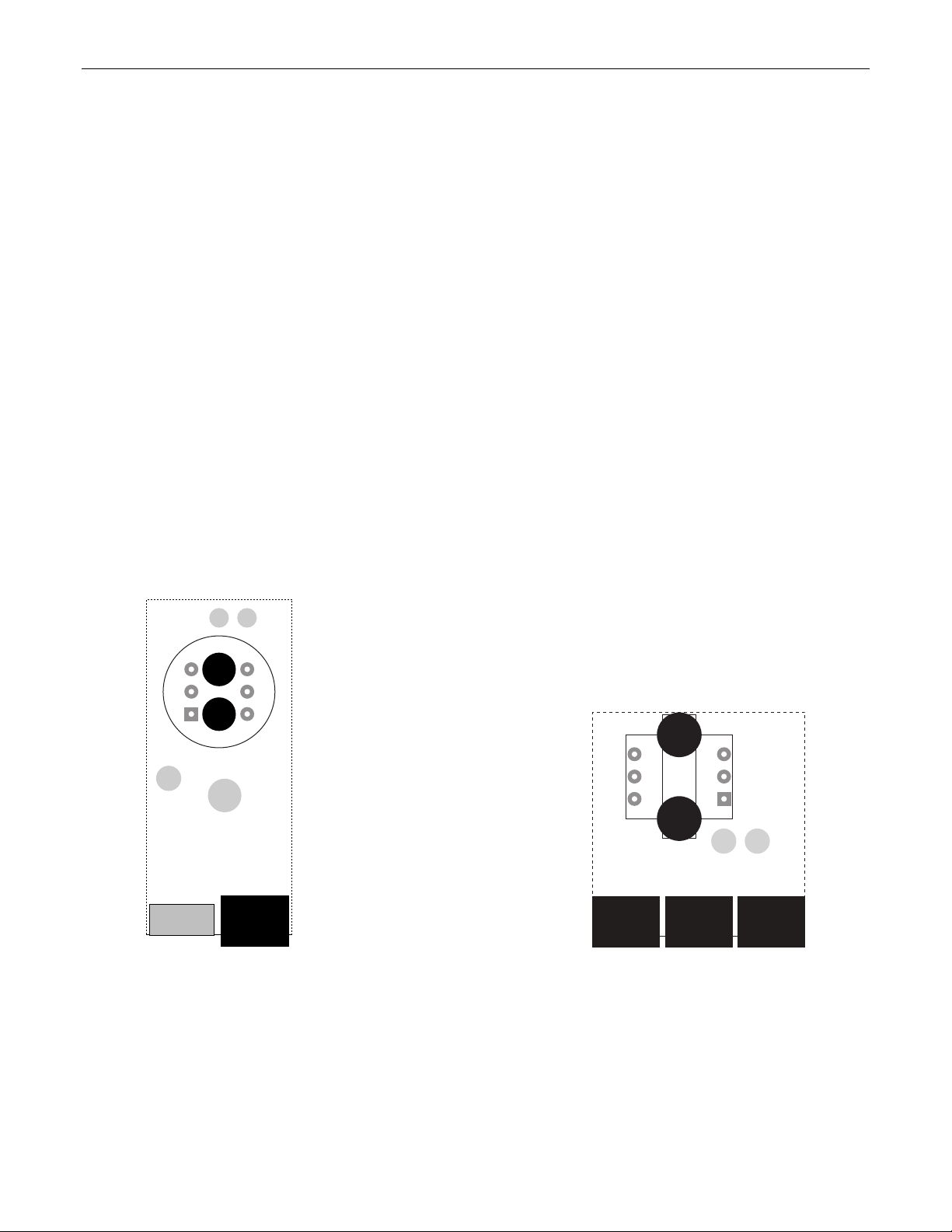
AC Power Cord: The power transformer provides 27 Volts AC to
the mixer, and is detachable via a 5-pin DIN connector. The mixer
has two internal ‘self-resetting’fuses (there are no user
serviceable parts inside the unit). If the internal fuses blow, they
will attempt to re-set after a short period. However, this may be an
indication that the mixer requires service.
Main Output: This plug-in barrier strip provides the balanced line-
level Main Output from the mixer. An output isolation transformer
(model IT-B) is available as a user installed option (see Options on
pg. 4). For balanced connection, wire high (+), low (-), and ground
(d). For unbalanced connection, wire high (+) and ground (d),
leaving (-) unconnected. Signal level will be reduced by 6dB when
output is unbalanced. Main Output level is affected by the front
panel Master control, as well as by remote control (see Remote
below).
Stack In: This plug-in barrier strip provides the balanced line-level
Stack In to the mixer. Signal entering here is combined with
signals from the input channels, and is then sent to the Main
Output section. When using multiple 801i mixers within a system,
connect Main Output of one mixer to Stack In of the next mixer,
and so forth. All mixers except the final 801i should be assigned
as ‘slaves’(see Master DIP Switches below). For balanced
connection, wire high (+), low (-), and ground (d). For unbalanced
connection, wire high (+) and ground to both (d) & (-).
Remote: This plug-in barrier strip provides connection for an
optional remote master level control (model RP-L1) (see Options
on pg. 4). An external potentiometer (5k~50k ohm linear taper) or
external ramp voltage (0~+10VDC) can also be used.
Potentiometers are wired high (V), wiper (C), and low (d). Ramp
voltage is wired positive (C), and ground (d). The Remote port
must be enabled before remote master level control is possible
(see Master DIP switches below).
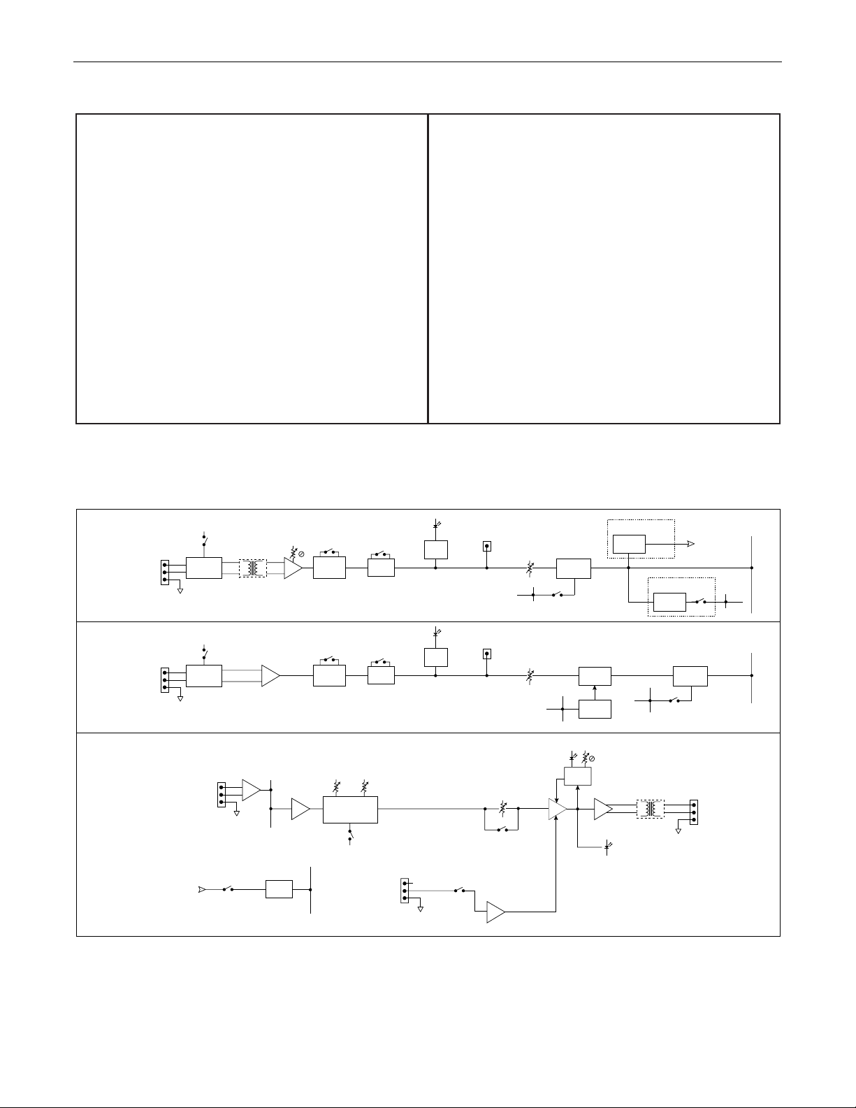
Input & Direct Out (Channels 1~8 & Aux):These plug-in barrier
strips provide the balanced mic/line Inputs to the mixer (Channels
1~8 only). Input isolation transformers (model IT-A) are available
as a user installed option (see Options on pg. 4). For balanced
connection, wire high (+), low (-), and ground (d). For unbalanced
connection, wire high (+) and ground to both (d) & (-). Phantom
power (+24VDC) is available (see DIP Switches below), with +48V
phantom power as an option (model 48VPS) (see Options on pg.
4). The Aux input accepts either balanced mono line input or
unbalanced stereo line input (see DIP switches below). Aux input
cannot accept mic input signal, or the optional input isolation
transformer, and does not provide phantom power. Unbalanced
'pre-fader' Direct Outputs are available on Channels 1~8 & Aux,
using the (d. out) & (d) terminals.
Master DIP Switches: These switches assign functions to the
mixer as a whole (when pushed up). Slave assigns the mixer as
an expander to a ‘master’mixer. Tone Out bypasses the front
panel tone controls (Bass & Treble). Override allows automatic
muting of other inputs when signal is present in Channel 1.
Remote allows remote control of Main Output level, by enabling
the Remote terminals (see above).
DIP Switches (Channels 1~8 & Aux):These switches assign
functions to the individual inputs (when pushed up). Pad
attenuates channel signal -18dB (-10dB at Aux) for line input.
Priority disables Channel 1 Override muting for that channel.
Phantom (Channels 1~8 only) turns on phantom power (for
condenser mics). Duck Aux (Channels 1~8 only) allows channel
signal presence to activate -15dB attenuation at Aux input
(ducking). HP Filter enables a high-pass filter on the input
(6dB/octave @ 170Hz). Sum (Aux only) converts Aux from
standard balanced input to stereo (L/R) summing input.

4
OPTIONS
Remote: The output level of an 801i mixer can be remotely controlled via an external potentiometer (5k~50k ohm linear taper) or ramp
control voltage (0~+10VDC). An RP-L1 remote control panel is available as an option (see diagram below). Potentiometers are wired high
(V), wiper (C), and low (d). Ramp voltage is wired positive (C) and ground(d). The Remote port of the 801i mixer must be enabled before
remote control of output level is possible (see Master DIP Switches on pg. 3). Remote control does not change physical settings on the
801i mixer, it only attenuates from the maximum level settings established at the mixer.
CV
green (to ' ')
red (to 'C')
white (to 'V')
low (ccw)
wiper
high (cw)
cwccw
w
REMOTE
RP-L1
25kΩ
linear

5
OPTIONS
NOTE: The 801i chassis must be disassembled before installing input/output transformers: 1) remove plug-in barrier-strip connectors
from rear panel. 2) remove top panel (2 screws at bottom of each side panel; 1 screw at top-center of front panel; 1 screw at top-center of
rear panel). 3) remove screws from front panel (2 screws at each end; 2 screw at center). 4) remove mounting screws from circuit board
(9 screws in front of input connectors; 1 screw in front of Main Output connector; 1 screw behind channel 5 +10 indicator; 1 screw behind -
20 indicator). 5) gently pull circuit board forward (front panel comes forward; connectors exit rear panel). 6) rotate front panel/circuit
board upward, away from chassis (leave rear portion of circuit board in chassis, being careful not to strain power cord connections).
Input Transformers: To install input transformers (see diagram below): 1) locate the transformer positions on the circuit board (circle
area located in front of input connector & DIP switches on each channel). 2) un-solder & remove the 2 capacitors located within each of
the appropriate circle areas. 3) install & solder an input transformer at each of the appropriate circle areas (transformer pin 1, designated
by a red dot, must be inserted into the proper hole, designated by a square).
Output Transformer: To install output transformer (see diagram below): 1) locate the transformer position on the circuit board (rectangle
area located in front of Main Output connector). 2) un-solder & remove the 2 capacitors located within the rectangle area. 3) install &
solder the output transformer at the rectangle area (transformer pin 1, designated by a red dot, must be inserted into the proper hole,
designated by a square).
DIP
switches
input
connector
cap
cap
channels 1~8
INPUT TRANSFORMERS
main out
connector
stack in
connector
remote
connector
cap
cap
OUTPUT TRANSFORMER

6
SPECIFICATIONS & BLOCK DIAGRAM
Frequency Response (20Hz~20kHz @ +4dBu):
THD+Noise (20Hz~20kHz @ +4dBu):
Equivalent Input Noise (20Hz~20kHz, 150Ωterm.):
Output Noise (20Hz~20kHz):
master level control down
master level & one channel at nominal
Maximum Gain:
mic input to main output
stack input to main output
Output Tone Controls:
Treble
Bass
Channel High-Pass Filters:
frequency
slope
Output Limiter:
atack time
release time
threshold range
Output Impedance:
main output (balanced)
channel direct (unbalanced)
Maximum Output:
main output
channel direct
Input Impedance:
mic/line inputs (balanced)
stack input (balanced)
Maximum Input:
mic/line input
stack input
Crosstalk (channel-to-channel @ 1kHz):
Power Consumption (115/230VAC 50/60Hz):
Dimensions:
height (1 rack space)
width
depth
Weight:
+0/-1dB
< 0.08%
-123dBu
< -86dB
< -78dB
85dB
9dB
±10dB @ 10kHz
±10dB @ 100Hz
-3dB @ 170Hz
6dB/octave
1~2 mS (program dependent)
100~500 mS (program dependent)
-4dBu ~ +24dBu
200 ohms
100 ohms
+24dBu
+18dBu
5.1k ohms
40k ohms
+20dBu
+24dBu
-60dB
< 15 watts
1.75 inches (44mm)
19 inches (483mm)
7 inches (178mm)
6 lbs. (2.72kg)
Master Section
priority
bus
master
level
Input Channels
Aux Input
phantom
power
discrete
transistor
preamp
trim peak
detect
+10dB
+24V
(+48V option) direct
out
mix
bus
duck
bus
level
channels 1-8 only
signal
detect
duck
logic
main
stack
mix
bus
main
output
Σ
VCA
input
mono sum/
balanced
slave
direct
out
gate
override
channel 1 only
signal
detect
priority bus
HP
filter
priority
peak
detect
+10dB mix
bus
duck
bus
level
gate
priority
bus
HP
filter
priority
EQ
+/-10dB @ 100Hz
+/-10dB @ 10kHz
bass treble
tone out
from ch 1
limit
detect
limit threshold
input
transformer
(option)
-20
output
transformer
(option)
remote level
control
Σ
+10V remote
15dB
duck
input
18dB
pad
10dB
pad
override
override
logic

WARRANTY
BIAMP SYSTEMS IS PLEASED TO EXTEND THE FOLLOWING 5-YEAR
LIMITED WARRANTY TO THE ORIGINAL PURCHASER OF THE
PROFESSIONAL SOUND EQUIPMENT DESCRIBED IN THIS MANUAL.
BIAMP Systems expressly warrants this product to be
free from defects in material and workmanship for a
period of 5 YEARS from the date of purchase as a
new product from an authorized BIAMP Systems
dealer under the following conditions.
1. In the event the warranted BIAMP Systems product
requires service during the warranty period, BIAMP
Systems will repair or replace, at its option, defective
materials, provided you have identified yourself as the
original purchaser of the product to any authorized
BIAMP Systems Service Center. Transportation and
insurance charges to and from an authorized Service
Center or the BIAMP Systems factory for warranted
products or components thereof to obtain repairs shall
be the responsibility of the purchaser.
2. This warranty will be VOIDED if the serial number
has been removed or defaced; or if the product has
been subjected to accidental damage, abuse, rental
usage, alterations, or attempted repair by any person
not authorized by BIAMP Systems to make repairs; or
if the product has been installed contrary to BIAMP
Systems's recommendations.
3. Electro-mechanical fans, electrolytic capacitors,
and the normal wear and tear of appearance items
such as paint, knobs, handles, and covers are not
covered under this warranty.
4. BIAMP SYSTEMS SHALL NOT IN ANY EVENT BE
LIABLE FOR SPECIAL, INCIDENTAL, OR
CONSEQUENTIAL DAMAGES, INCLUDING LOST
PROFITS, LOSS OF USE, PROPERTY DAMAGE, INJURY
TO GOODWILL, OR OTHER ECONOMIC LOSS OF ANY
SORT. EXCEPT AS EXPRESSLY PROVIDED HEREIN,
BIAMP SYSTEMS DISCLAIMS ALL OTHER LIABILITY TO
PURCHASER OR ANY OTHER PERSONS ARISING OUT
OF USE OR PERFORMANCE OF THE PRODUCT,
INCLUDING LIABILITY FOR NEGLIGENCE OR STRICT
LIABILITY IN TORT.
5. THIS WARRANTY IS IN LIEU OF ALL OTHER
WARRANTIES EXPRESSED OR IMPLIED. BIAMP
SYSTEMS EXPRESSLY DISCLAIMS ALL IMPLIED
WARRANTIES OF MERCHANTABILITY AND FITNESS
FOR A PARTICULAR PURPOSE. THE REMEDIES SET
FORTH HEREIN SHALL BE THE PURCHASER'S SOLE
AND EXCLUSIVE REMEDIES WITH RESPECT TO ANY
DEFECTIVE PRODUCT. THE AGENTS, EMPLOYEES,
DISTRIBUTORS, AND DEALERS OF BIAMP SYSTEMS
ARE NOT AUTHORIZED TO MODIFY THIS WARRANTY
OR TO MAKE ADDITIONAL WARRANTIES BINDING ON
BIAMP SYSTEMS. ACCORDINGLY, ADDITIONAL
STATEMENTS SUCH AS DEALER ADVERTISEMENTS
OR REPRESENTATIONS DO NOT CONSTITUTE
WARRANTIES BY BIAMP SYSTEMS.
6. No action for breach of this warranty may be
commenced more than one year after the expiration of this
warranty.
Thank you for purchasing BIAMP SYSTEMS...
AMERICAN SOUND CRAFTSMANSHIP
Biamp Systems
10074 S.W. Arctic Drive
Beaverton, Oregon 97005
(503) 641-7287
http://www.biamp.com
585.0204.00

BIAMP SYSTEMS
10074 SW Arctic Drive
Beaverton, OR USA 97005
as the manufacturer, hereby declares that the following described product, in our delivered version,
complies with the provisions of the DIRECTIVES as noted herein. In case of alteration of the product,
not agreed upon or directed by us, this declaration is no longer valid.
Product: Model: BIAMP801i
Description: Mic/Line Mixer
Applicable EC Directives: EMC Directive (89/336/EEC) LVD Directive (73/23/EEC)
Applicable Harmonized Standards: EN55103-1 emissionsEN55103-2 immunity
EN60065 safety
Special Considerations for Product Environment or Compliance:
Shielded cabling must be used for system connections. The apparatus is deemed incapable of
producing harmonic emissions or flicker levels sufficient enough to interfere with other apparatus as
noted in EN61000-3-2 and EN61000-3-3.
This apparatus operates from a removeable external power source at voltages below the levels
encompassed by the LVD. The external power source complies with the applicable requirements of
EN60065. The apparatus itself is outside of the scope of the LVD and presents no hazardous
voltages, as defined in the LVD. For compliance, the apparatus shall be powered only from the
separate CE marked BIAMP SYSTEMS power source.
RF interference conducted through interconnect cabling may cause varying degrees of random
signal degradation. The effect of increased noise or distortion due to this interference is typically
masked by the desired signal. In no instance is operation inhibited.
The Technical Report/File is maintained at: Biamp Systems
10074 S.W. Arctic Drive
Beaverton, OR USA 97005
phone: (503) 641-7287 fax: (503) 626-0281
e-mail: biamp@biamp.com
Authorized Representative: Glenn Westerfield, Test and Compliance Engineer
Authorized Representative Signature:
Issued: 09-27-2004
Declaration of Conformity


Other manuals for 801I
1
Table of contents
Other Biamp Mixer manuals

Biamp
Biamp 44 User manual

Biamp
Biamp ADVANTAGE DP/M 28 User manual

Biamp
Biamp advantage DLA93 User manual

Biamp
Biamp ADVANTAGE 601e User manual

Biamp
Biamp RPM SERIES User manual

Biamp
Biamp 301 User manual

Biamp
Biamp IWA250 User manual

Biamp
Biamp SCM 7600 User manual

Biamp
Biamp VRAM User manual

Biamp
Biamp IWA250 User manual

Biamp
Biamp DJ5600 User manual

Biamp
Biamp ADVANTAGE SPM522D User manual

Biamp
Biamp AUTOONE User manual

Biamp
Biamp MIXPAK PLUS User manual

Biamp
Biamp autoTWO User manual

Biamp
Biamp RACKMAX II User manual

Biamp
Biamp 801 User manual

Biamp
Biamp 801I User manual

Biamp
Biamp DJ 5600 User manual

Biamp
Biamp IWA SERIES User manual