InPOWER SS-FD23 User manual
SS-FD23 Owner’s Manual
Document: OM-255 Version Code: B
Date: May 31, 2023 Date: Aug 31, 2023
© Copyright 2023 InPower LLC
Page
1 of 16
InPower LLC
8311 Green Meadows Drive
Lewis Center, Ohio 43035 USA
740-548-0965
www.InPowerLLC.com
Electrical System Solutions
OWNERS MANUAL
InPower Model SS-FD23
Contents
1. Introduction............................................................ 2
2. Installation Procedures.......................................... 3
3. Operation............................................................... 6
4. Mechanical Drawing .............................................. 10
5. Status LED and Troubleshooting........................... 11
6. Installation Location............................................... 13
7. Start/Stop Ignition/BCM/SS-FD23 Wiring.............. 16
8. Contact Information ............................................... 16
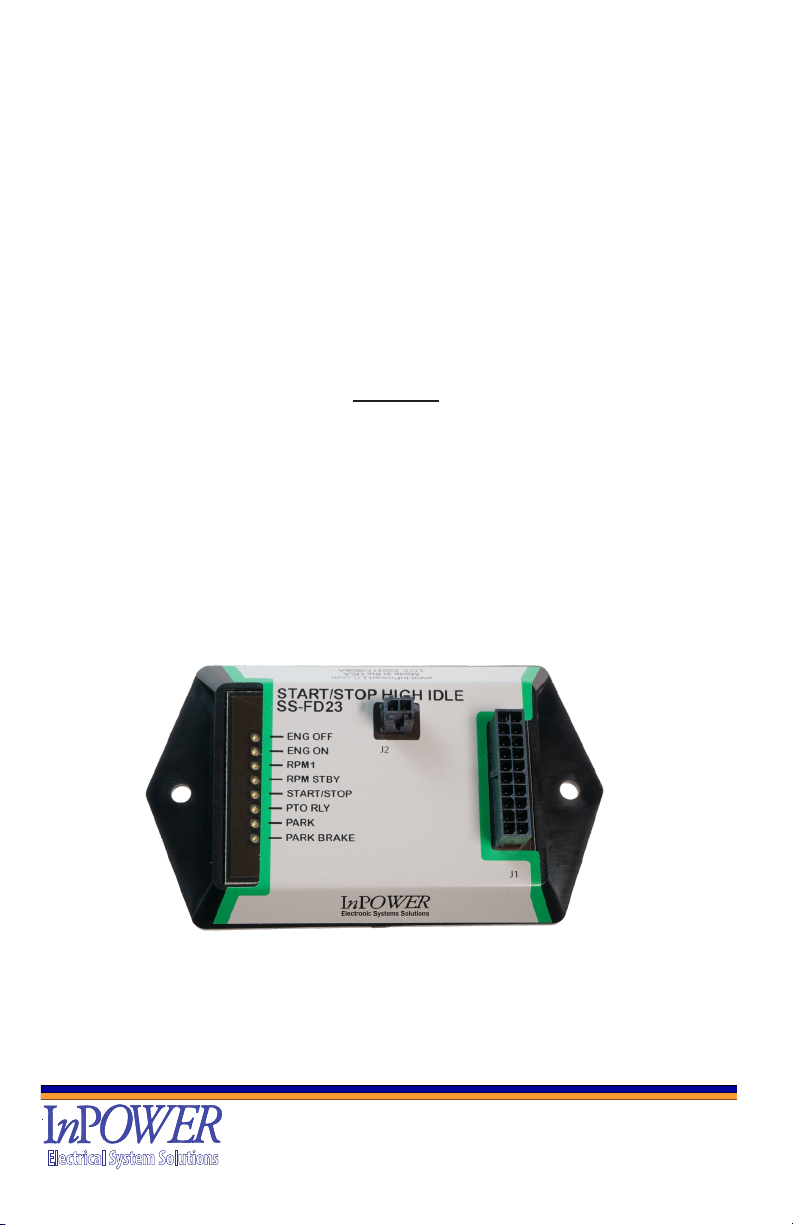
Electronic Start/Stop/Elevated Idle Control Module
for Ford 2023 F250-F600

SS-FD23 Owner’s Manual
Document: OM-255 Version Code: B
Date: May 31, 2023 Date: Aug 31, 2023
© Copyright 2023 InPower LLC
Page
2 of 16
InPower LLC
8311 Green Meadows Drive
Lewis Center, Ohio 43035 USA
740-548-0965
www.InPowerLLC.com
Electrical System Solutions
1. Introduction
InPower’s SS-FD23 Start/Stop/Elevated Idle Module provides Start/Stop Functions
and an elevated Idle selection. This product is compatible with the 2023 F250-F600. It
is designed to be mounted under the Steering column near the OBDII connector and
the Trailer Brake Controller Module.
Modules come with various modes of control: Start, Stop, and two preset RPM speeds
(one default setting and another selectable).
Note: The elevated idle functions will only operate if the Chassis Ready
Conditions are satised. LED diagnostic indicators are provided to aid in system
troubleshooting. These LEDs are located on the module opposite the connector.
Chassis Ready Conditions typically could be:
• No vehicle speed
• Accelerator not depressed
• Engine up to Operating Temperature
• Shifter in Park
• Service brake not depressed
• Engine running below base idle
• No Diagnostic Trouble Code (DTC). Check Engine light must be off.
• Other hindering conditions will be detailed in the Body Builder’s Guide (www.
eet.ford.com/truckbbas/)
SS-FD23-01 - Special for Stellar Has Data Bus T-Harness
SS-FD23-02 Standard Product - Harness with Blunt Cut Wires DataBus T-Harness
SS-FD23-03 - T-Harness for DataBus with Short Blunt Cut Wires for all IO
SS-FD23-04 - Harness with T-Harness Ignition Connector
The SS-FD23-02 kit includes two cables.
The cable 1 connects the module to the SEIC Interface (Group 3) blunt cut wires, and
connects to the Ignition Switch (Group 1) via Blunt Cut Wires for controlling the engine.
Control Interface (Group 2) Blunt Cut Wires connect the control inputs and outputs for
the SS-FD23-02 and to the PTO. Cable 1 also provides connections to Battery and
Ground, and also provides decoded PARK and PARK BRAKE signals.
The cable 2 connects to the Trailer Brake Controller Module (See Page 12) and picks
up the Data Bus via a T-Harness. This provides PARK and PARK BRAKE data to the
SS-FD23-02 which provides discrete wires to the user for those signals.
The SS-FD23-04 kit includes two cables.
The cable 1 connects the module to the SEIC Interface (Group 3) blunt cut wires, and
connects to the Ignition Switch (Group 1) via T-Harness for controlling the engine.
Control Interface (Group 2) Blunt Cut Wires connect the control inputs and outputs for
the SS-FD23-04 and to the PTO. Cable 1 also provides connections to Battery and
Ground, and also provides decoded PARK and PARK BRAKE signals.

SS-FD23 Owner’s Manual
Document: OM-255 Version Code: B
Date: May 31, 2023 Date: Aug 31, 2023
© Copyright 2023 InPower LLC
Page
3 of 16
InPower LLC
8311 Green Meadows Drive
Lewis Center, Ohio 43035 USA
740-548-0965
www.InPowerLLC.com
Electrical System Solutions
The cable 2 connects to the Trailer Brake Controller Module (See Page 12) and
picks up the Data Bus via a T-Harness. This provides PARK and PARK BRAKE
data to the SS-FD23-04 which provides discrete wires to the user for those signals.
Truck Body Builder Advisory Service:
www.eet.ford.com/truckbbas/
1.1 Interface Selection
This section discusses the interface for the SS-FD23-02
1. The SS-FD23 needs to be located close to the Steering Column so that the
wires that connect to the ignition switch RUN wire (Yellow-Group 1) to the
RUN-IN and RUN-OUT (White-Group 1) can be connected easily. The Start
Signal (Lt. Blue) goes to the START wire from the ignition switch.
2. The connection to the Data Bus via a T-Harness to the Trailer Brake
Controller Module (Page 12) so it needs to be located close to it near the
OBDII connector.
3. ENABLE (Pink, Group 2) is a 12V signal that will enable the SS-FD23 for
operation and turn on the interfaces.
4. RPM1-Gnd Pulse (Tan, Group 2) requires a pulse to Ground to select RPM1,
and a second Ground Pulse to turn RPM1 off (back to RPM STBY - Default).
5. RPM1-12V (Violet, Group 2) requires 12V to enable RPM1, and removing
12V from this line will turn RPM1 off (back to RPM STBY - Default). RPM
Gnd Pulse (Tan) is not available as long as 12V is applied to this line.
6. START/STOP (Brown, Group 2) requires a pulse to Ground to Turn Engine
On, and a second Ground Pulse to Turn the Engine Off. RPM is used to
check Engine Status.
7. The Power Connections are Battery (Red, Group 2) rated at 15 Amps, and
Ground (Black, Group 2) connected to Battery Ground.
8. Outputs
• The PTO Interface is the PTO OUT (Orange, Group 2) 12V (10A Max)
which turns on when SEIC PTO RLY goes to Ground.
• U-IGNITION 12V (Yellow/Red, Group 2) remains on as Engine Stop (5A
Max) is on. Turned ON/OFF when ENABLE is turned ON/OFF. This is
for uptter components needing to remain powered during a shut down
sequence.
• Decoded PARK (Dk Blue Group 2) and PARK BRAKE (White/Black
Group 2) discrete wires are available as discrete wires (GND True).
These reect the current status of the PARK BRAKE and PARK for the
vehicle and are enabled by the RUN (+12V True) line.
(Total for PTO and Ignition 12 should be less than 13A total)
9. SEIC Blunt Cut Wires
• PTO_RLY (Lt Blue, Group 3) - PTO Relay
• PTO REQ1 (Yellow/Green, Group 3) PTO Request
• PTO RPM (Dark Green, Group 3)

SS-FD23 Owner’s Manual
Document: OM-255 Version Code: B
Date: May 31, 2023 Date: Aug 31, 2023
© Copyright 2023 InPower LLC
Page
4 of 16
InPower LLC
8311 Green Meadows Drive
Lewis Center, Ohio 43035 USA
740-548-0965
www.InPowerLLC.com
Electrical System Solutions
!
!
Warning!
2. Installation
2.1 Safety Precautions
This electronic Start/Stop/Elevated Idle product has been designed and manufactured
to meet the intended application requirements and specications. Any modications to
the product or to the installation procedure can be dangerous and will void InPower’s
warranty.
• Read and understand the instructions in this manual and other manuals before
starting the installation.
• Make sure that the vehicle battery power is disconnected during the
installation of the Start/Stop module.
• Reconnect the battery when the system installation is complete.
• Wear appropriate safety equipment, such as protective eyeglasses, faceshield and
clothing when installing equipment and handling the battery.
• Be careful when working near a battery. Make sure that the area is well ventilated
and that there are no ames near the battery. Never lay objects on the battery that
can short the terminals together. If battery acid gets in your eyes, immediately seek
rst aid. If acid gets on your skin, immediately wash it off with soap and water.
• Avoid disconnecting and making connections to the SEIC and PTO with the vehicle
powered.
2.2 Getting Started
IMPORTANT NOTE: Once again! Please obtain the specic SEIC installation
instructions for your vehicle model from Ford. Wire colors and locations may vary
from model to model and even between different years for the same model. The
guide may be obtained from Ford’s Body Builder Advisory Service.
(www.eet.ford.com/truckbbas/)
Carefully disconnect the battery before making any electrical connections.
2.3 Mounting
Mount the SS-FD23-02 module under the dash near the steering column.
2.4 Wiring
First, identify the GROUND Wire (Black, Pin12, Group 2) and connect it to a solid
battery ground prior to any other connections.
Connect the 12V power (Battery, Red, Pin17, Group 2) to a fused battery feed (Battery
still disconnected on the vehicle).
Proceed with connecting the Group1 wires to the Ignition switch (RUN-IN, RUN-OUT,
and START) then connect the Group2 Wires to the Control Interfaces (descriptions
called out in the 2.5 Control Interface section). Also refer to Section 7 Start/Stop Ignition/
BCM/SS-FD23-02 Wiring Page 16.
SS-FD23 Owner’s Manual
Document: OM-255 Version Code: B
Date: May 31, 2023 Date: Aug 31, 2023
© Copyright 2023 InPower LLC
Page
5 of 16
InPower LLC
8311 Green Meadows Drive
Lewis Center, Ohio 43035 USA
740-548-0965
www.InPowerLLC.com
Electrical System Solutions
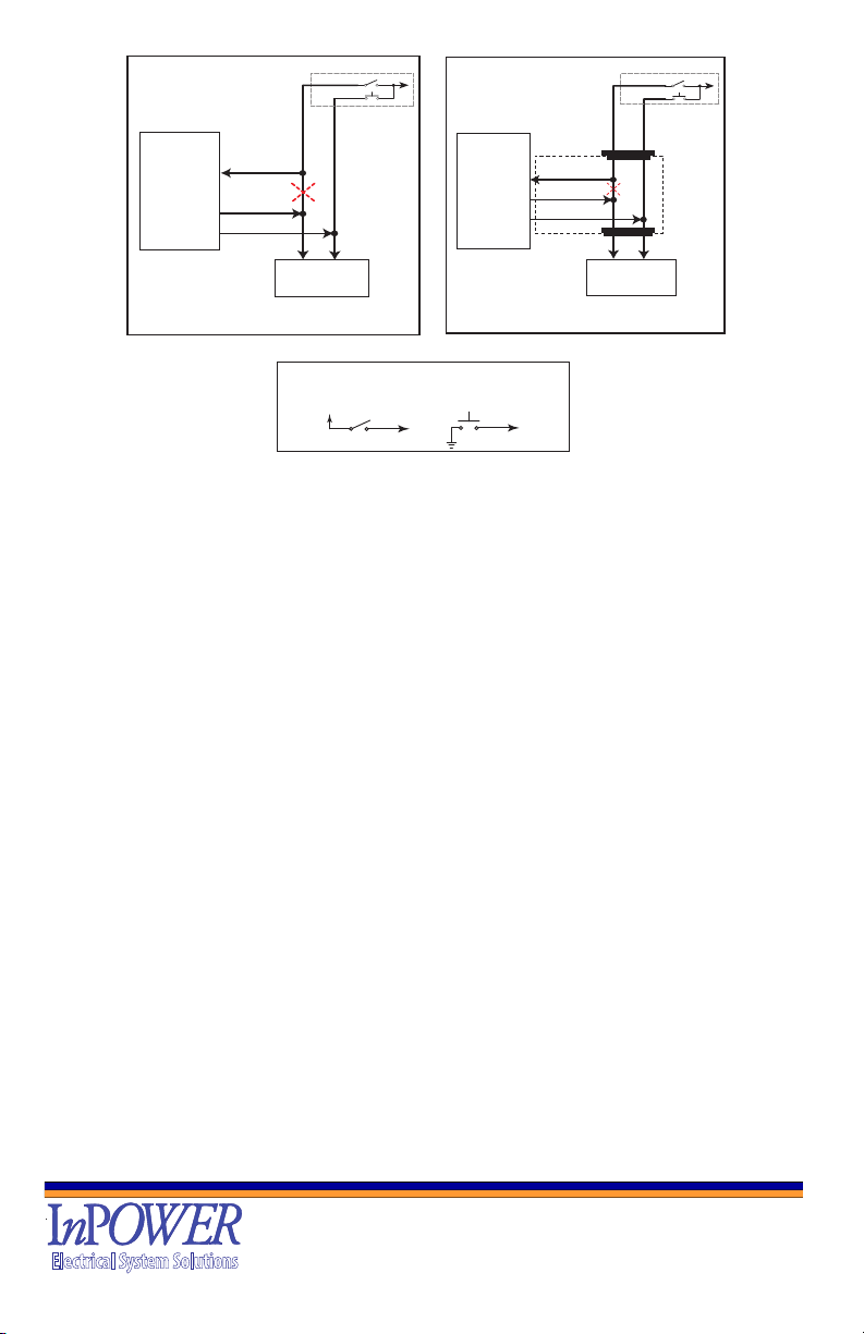
Yellow
White
Body Control
Module
RUN
Ignition Switch Connection Diagram
Blunt Cut Wires SS-FD23-02
START
Violet/Orange
SS-FD23-02
RUN-IN
RUN-OUT
START
Ignition Switch
Start
RUN (IGN)
Yellow
White
Body Control
Module
RUN
Ignition Switch Connection Diagram
Connectorized SS-FD23-04
START
Violet/Orange
SS-FD23-04
RUN-IN
RUN-OUT
START
Ignition Switch
Start
RUN (IGN)
SS-FD23-04 Cable
Momentary to GND
+12V
+12V Level
Types of Switches for Control of SS-FD23
RUN
After termination of all wires, connect the the J1 cable to the SS-FD23.
2.5 Control Interface (Operation)
Determine the combination of two high idle speed modes needed (RPM1 and RPM-
STBY).
The customer needs to supply switches for the ENABLE, START/STOP, and RPM1
modes. These modes are selected by wires in the Group 1 bundle.
The RUN-IN line provides power for the SS-FD23 and if not present, places the unit in
an ultra low power state (micro Amperes).
The RUN-OUT line provides the control for the Body Control Module to indicate
the Ignition is on to the Body Control Module that the vehicle is ready to start (if all
conditions are conducive)
The ENABLE 12V line (Group 2 - Pink Wire) will take the Module out of StandBy when
True. If Ignition is ON but Enable is not True, the SS-FD23 will monitor the Chassis
Data Bus for status, but will not operate the Start-Stop, High Idle functions and
outputs. If Enabled, removal of +12V from this Pin will shut off the High Idle, returning
the engine to running at normal idle, turn off the outputs (except for PARK and PARK
BRAKE), and will place the SS-FD23 in StandBy.
The RPM1 Trigger Gnd Pulse on this Wire (Group 2 - Tan) if in RPM STBY, will
change the system to RPM1. A second Pulse to Ground will change the system to
RPM STBY.
The RPM1 12V on this Wire (Group 2 - Violet) if in RPM STBY, will change the system
to RPM1 as long as 12V is present. Removing 12V will return the unit to RPM STBY.
The START/STOP Switch is connected the START/STOP Input Wire (Group 2 - Brown
Wire) to supply a Ground Pulse to Start the Engine (unit will enter into RPM STBY
Mode). A second Pulse to Ground will Stop the Engine. RPM messages are used to
verify Engine Status. The START/STOP LED indicates switch activity.
SS-FD23 Owner’s Manual
Document: OM-255 Version Code: B
Date: May 31, 2023 Date: Aug 31, 2023
© Copyright 2023 InPower LLC
Page
6 of 16
InPower LLC
8311 Green Meadows Drive
Lewis Center, Ohio 43035 USA
740-548-0965
www.InPowerLLC.com
Electrical System Solutions
PARK - (Dk Blue - Group 2) A GND True decoded signal from the Data Bus that
indicates the gearshift is in Park Position (Flashes if not in position). Output is enabled
by the RUN line.
PB (Park Brake) - (White/Black - Group 2) A GND True decoded signal from the Data
Bus that indicates if the Park Brake is set (Flashes if not set). Output is enabled by the
RUN line.
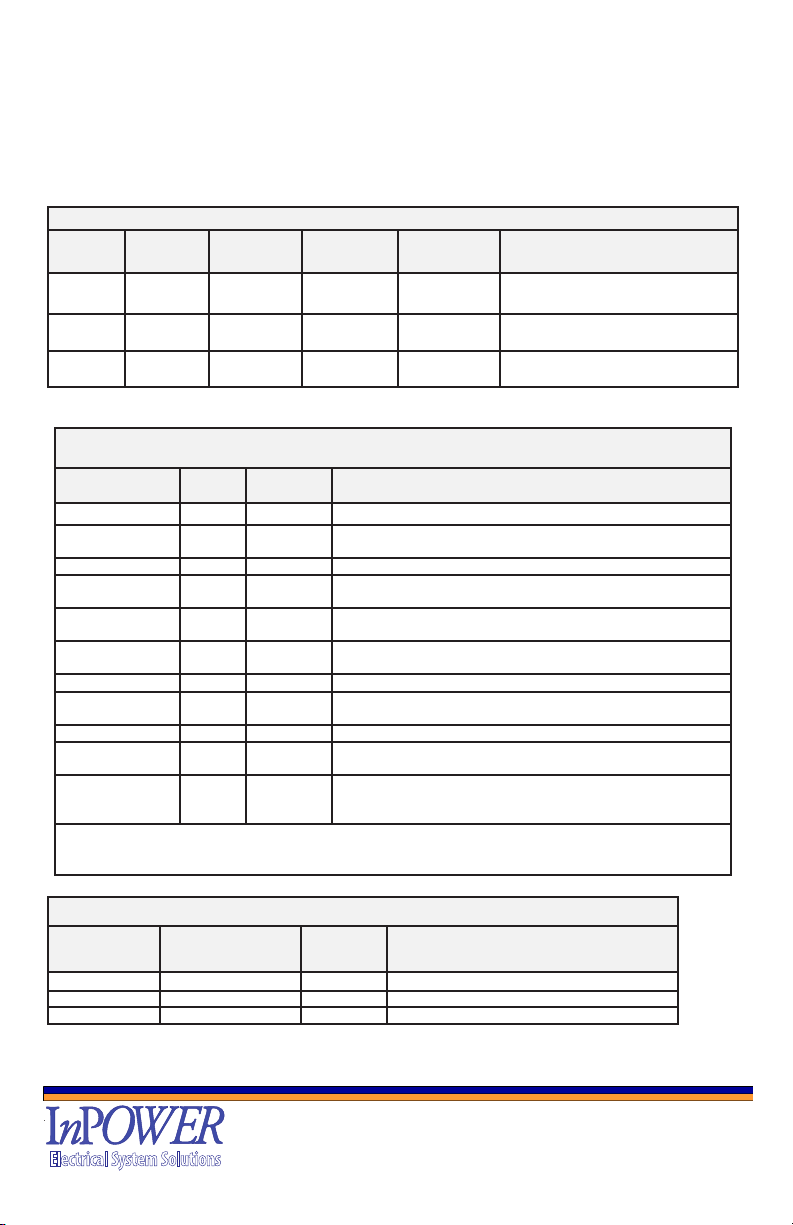
Group 1
Function Wire
Color
Connector
P1 Pin #
Connection
SS-FD23-02
Connection
SS-FD23-04
Description
RUN-IN Yellow 1 Blunt Cut Connector To the SS-FD from the Ignition
Switch
RUN-
OUT
White 11 Blunt Cut Connector Goes from the SS-FD to the Body
Control Module
START Violet/
Orange
14 Blunt Cut Connector Goes to the START Wire from the
Ignition Switch
Group 2
Function Wire
Color
Connector
P1 Pin #
Function
ADJUST** Lt Grn 3 Adjustment for RPM1 and RPM STBY
PARK Dk Blue 4 Current State of PARK Output (GND True). Output available if
RUN is True. (1A Sink Max)
ENABLE 12V Pink 5 IN1- Enable 12V - Wakes up SS-FD23-02 and Enables Functions
RPM1 (GND)** Tan 6 1st Gnd Pulse will select RPM1, 2nd Gnd Pulse will return the
module to RPMSTBY
RPM1 (12V)** Violet 7 12V activates RPM1 as long as it’s present. This automatically
masks out any selection by a GND Pulse on Pin 6 (RPM1(GND))
START/STOP Brown 8 In4- Start/Stop GND - Pulse to Gnd Starts Engine, 2nd Pulse to
Gnd Stops Engine.
GND** Black 12 Battery Ground connect to a solid Battery Ground.
Park Brake White/
Black
13 Decoded Park Brake Out (GND True) - Current state of PB, Output
available by RUN = TRUE. (1A Sink Max)
BATTERY** Red 17 Battery +12Vdc connect to Battery +12 (Rated at 15Amps)
PTO OUT*Orange 19 PTO Output connect to PTO Solenoid maximum 10 Amps (turns
on when SEIC PTO-RLY goes to Ground)
U-IGNITION* Yellow/
Red
20 Ignition that will remain on during engine stop (maximum 5 Amps)
and is disabled by Enable (used for Uptter Ignition dependent
components)
* Total Current of PTO_OUT and IGNITION should not be > 13 Amps DC.
** These wires are for use with setting remote variable RPM
SEIC Group 3
Function SS-FD-02 Wire
Color
P1 Pin # Signal Output Level
PTO RLY Lt Blue 2 Ground Active Indicates OK to Engage PTO
PTO RPM Dk Green 10 0.4-4.5V
PTO REQ1 Yel/ Green 16 Positive (Out High 6)

SS-FD23 Owner’s Manual
Document: OM-255 Version Code: B
Date: May 31, 2023 Date: Aug 31, 2023
© Copyright 2023 InPower LLC
Page
7 of 16
InPower LLC
8311 Green Meadows Drive
Lewis Center, Ohio 43035 USA
740-548-0965
www.InPowerLLC.com
Electrical System Solutions
PTO OUT (Orange Wire - Group 2) provides a connection to the PTO Solenoid
capable of driving up to 10 Amps max (Note PTO OUT and U-IGN should never
exceed a combined current of 13 Amps).
U-IGNITION - 12V Uniterrupted Ignition (Yellow/Red Group 2) is ON whenever
ENABLE it ON and is used for support of uptter components that may need to remain
powered during the engine shut-down sequence.
The Power Connections are Battery (Red wire - Group2) rated at 15 Amps, and
Ground (Black - Group2) connected to Battery Ground.
PTO RLY (PTO Relay) - (Lt. Blue, Group 3) Indicates the PTO Relay is OK to be
engaged. LED Indicator ashes if not OK - Usually indicates problems with Chassis
Ready Conditions.
SEIC PTO RPM (Dk Green Wire - Group 3)
SEIC PTO Req1 (Yellow/Green Wire - Group 3)
3. Operation
When the vehicle is parked and Chassis Ready Conditions are satised, the Start
and Stop Functions and engine idle speed may be controlled by selection of one of the
modes: START, STOP, RPM1 (RPM STBY is ON when ENABLE is ON, ENG ON is
ON, and RPM1 is OFF). The preset RPM modes may be adjusted via applying +12V or
GND to the gray RPM ADJUST wire (RPM Adjustment Procedure, page 8).
Chassis Ready Conditions:
• No vehicle speed
• Parking brake set
• Shift selector in Park
• Accelerator not pressed
• Service brake not pressed
• Engine running and at Base Idle
• No Diagnostic Trouble Code (DTC). Check Engine light must be off.
NOTE:While the engine is in high idle, should the throttle be deactivated by one
of the Chassis Ready Conditions changing, the engine will return to normal speed.
The throttle will ash the diagnostic LEDs to indicate the cause of the deactivation.
Modes of Operation:
Enable:
Description:
Once the module is powered up by turning on the Ignition, it waits in StandBy mode
until a steady 12V enable signal is detected on the ENABLE input (Pink - Group2).
Then the module detects if Engine is ON or OFF via the Data Bus Engine RPM
message and goes to RPM-STBY if the Engine is ON. If the 12V enable signal is
removed the module returns to the low power mode after turning off all outputs and
all LEDs except the BUS ON (showing Bus trafc), and if the Engine is ON and High
Idle is selected, it will also return to standard Idle speed.
If the RUN is on, then the PARK and PARK BRAKE Outputs will be present.

SS-FD23 Owner’s Manual
Document: OM-255 Version Code: B
Date: May 31, 2023 Date: Aug 31, 2023
© Copyright 2023 InPower LLC
Page
8 of 16
InPower LLC
8311 Green Meadows Drive
Lewis Center, Ohio 43035 USA
740-548-0965
www.InPowerLLC.com
Electrical System Solutions
Engine Off/Start Section:
If the engine is OFF, the RUN is ON, and the ENABLE line at +12V, the module waits for
an open circuit to ground transition on START/STOP (Brown - Group2) input and then
runs the remote engine start routine. The START output will only be activated if the Park
Brake status and the Shift Park position are both True. If a RPM Messages show engine
activity, the module will transition to the Engine On routine. If RPM Messages do not
indicate operation within 5 seconds, the module will return to engine OFF state.
Enable: Steady +12V on Enable (Pink-Group 2) Enables Module and
Outputs
Start/Stop: A Pulse from Open to Gnd (Brown - Group 2) starts the
Engine if the Engine is Off and the Chassis Ready
Conditions are met, if Engine running, additional Pulse to
GND will Stop Engine.
Engine On/High Idle Section:
After a 5 second delay for the engine rpm to stabilize (via RPM messages), the PTO
REQ1 and PTO RPM outputs are turned on. The module now waits on an open circuit
to ground transition on the PTO RLY input indicating the SEIC is active. The module
now turns on the PTO output and the engine rpm is increased to the RPM STBY
speed.
When the unit is on, the default RPM will be RPM STBY. If an open circuit to ground
transition is detected on RPM1 input (Tan, Group2), the engine rpm is changed to the
RPM1 set point. If another open circuit to ground transition is detected on the RPM1
input, the engine rpm is changed back to the RPM STBY speed.
Preset RPM Modes
Activation:
When Off: Enable: Apply +12 V to Enable (Pink Wire - Group2)
Enables Unit
Engine is OFF: A GND Pulse on Start/Stop (Brown Wire - Group 2)
Starts Engine and goes to RPM STBY (Default High Idle RPM).
In RPM STBY: Apply GND Pulse to RPM1 (Tan Wire - Group2),
GND Pulse Select unit goes to RPM1.
In RPM1: Apply GND Pulse to RPM1 (Tan Wire - Group2) and the
unit goes to RPM STBY.
Or In RPM STBY: Apply 12V to RPM1 (Violet Wire - Group2),
+12V Select unit goes to RPM1 (locks out use of Tan Wire).
In RPM1: Remove 12V from RPM1 (Violet Wire - Group2) and the unit
goes to RPM STBY.
Deactivation:
In Any Mode: Removal of Enable 12V (Pink Wire - Group 2)
(Engine Running) Disables RPM1 or RPM STBY and Shuts Off High Idle
and goes to standard idle speed.
In RPM1 or STBY: A GND Pulse on Start/Stop (Brown Wire - Group 2)
(Engine Running) Stops Engine (U-Ignition Remains ON)
Default RPM Settings
+/- 5% Tolerance (Ford Interface Dependent)
RPM-STBY -
approx
870 RPM Gas, 950 RPM Diesel
RPM1 -
approx 1200 RPM Gas, 1500 RPM Diesel

SS-FD23 Owner’s Manual
Document: OM-255 Version Code: B
Date: May 31, 2023 Date: Aug 31, 2023
© Copyright 2023 InPower LLC
Page
9 of 16
InPower LLC
8311 Green Meadows Drive
Lewis Center, Ohio 43035 USA
740-548-0965
www.InPowerLLC.com
Electrical System Solutions
Calibration Range: Varies based on vehicle model.
Generally, 900 RPM to 2200 RPM (gas) or 900 to 2800 RPM (diesel)
Both the RPM STBY set speed and the RPM1 set speed are adjustable using the
ADJUST input. Any adjustments made will be automatically stored after an open
circuit is detected on the RPM ADJ input for 5 seconds.
To Calibrate an RPM, Select the RPM and then apply +12V (up) or Gnd (down) to
the RPM Adjust Input, (Lt. Green - Group 2).
RPM Adjustment Procedure:
1. Activate the mode desired for adjustment by Enabling the unit and then running
at the RPM-STBY or by selecting RPM1 with a Gnd pulse on the RPM1 (Tan
Wire - Group 2) Line or alternately by applying 12V to the Violet wire - Group 2
for RPM1.
2. Locate the ADJUST wire (Lt Green - Group 2) in the harness. Apply +12V
to this wire to raise the RPM or to GND the wire to lower the RPM. For each
second that +12V is connected to the RPM ADJUST wire (Lt Green, Group2),
the RPM will increase by 50 RPM per second. Likewise, if the RPM ADJUST
wire is tied to GND, the RPM will decrease at a rate of 50 RPM per second.
Releasing it from either +12V or Ground will steady the RPM.
Note: For each bump of less than a half second, the RPM will move by 25RPM up or
down (depending on whether Adjust is bumped to +12V or GND). If connected to +12V
or GND for a second (or more) it will increase by 50RPM for each second the Adjust is
connected to the voltage.
The new RPM Value is automatically saved after Five (5) Seconds
Note 1: A minimum of 910 RPM is recommended for PTO to activate.
Uninterrupted Ignition Output:
During the engine start and stop routines, the ignition run feed is turned off which
also turns off the ignition power to the uptter switches. The Uninterrupted Ignition
Output (Yellow/Red Wire, Group 2) provides a 12V output for equipment that needs
a continuous ignition signal. This output is rated at 5A.
IGN
(RUN)
ON?
No
ENABLE
ON?
Turn On
Module
Start Data Bus
Monitor
Yes
No
Blink ENG OFF
250mS On, 3Sec Off
All others OFF
Yes
No
Enable
Park and Park Brake Outputs
and Enable Start/Stop and
High Idle Functions
SS-FD23-02 IGNITION and ENABLE
Control for Module Operation

SS-FD23 Owner’s Manual
Document: OM-255 Version Code: B
Date: May 31, 2023 Date: Aug 31, 2023
© Copyright 2023 InPower LLC
Page
10 of 16
InPower LLC
8311 Green Meadows Drive
Lewis Center, Ohio 43035 USA
740-548-0965
www.InPowerLLC.com
Electrical System Solutions
Running Engine
Chassis
Conditions
Met?
Yes
Chassis Conditions
No vehicle speed
Parking brake set
Shift selector Park
Accelerator not pressed
Service brake not pressed
Engine run (< 1000 RPM)
Check Engine OFF.
No
ENABLE Pin at
12Vdc?
No
RPM1
Transition GND
to 12V?
RPM STBY
No
RPM1
Yes
Yes
RUN Conditions
Check
RUN
Conditions
Change (or
Start/Stop)?
Yes
No
Go to
Standard
Idle
RPM1
Transition GND
to 12V
No
Yes
Yes
Start/Stop
transition GND to
12Vdc?
No
Yes
Go to
STOP
Routine
No
Go to
Standard
Idle
Start/Stop
transition GND to
12Vdc?
No
Yes
Go to
STOP
Routine
RUN
Conditions
Change (or
Start/Stop)?
Stopped Engine
Chassis
Conditions
Met?
Yes
No
ENABLE Pin at
12Vdc?
No
Yes
RUN Conditions
Check
Start/Stop
transition GND to
12Vdc?
Yes
Start Routine
No
Chassis Conditions
No vehicle speed
Parking brake set
Shift selector Park
Accelerator not pressed
Service brake not pressed
Check Engine OFF.
Stopped Engine
Stopped Engine
Engine
Running? RPM
via Data Bus
Yes
No
No
Yes
5 Second Delay
RPM
Data Bus
Indicates
ENG RUN
No
Yes
Stopped Engine
Running Engine
5 Second Delay
Start/Stop Check
Start/Stop Check
SS-FD23 SW Operational Flow Chart
Engine
Running? RPM
via Data Bus

SS-FD23 Owner’s Manual
Document: OM-255 Version Code: B
Date: May 31, 2023 Date: Aug 31, 2023
© Copyright 2023 InPower LLC
Page
11 of 16
InPower LLC
8311 Green Meadows Drive
Lewis Center, Ohio 43035 USA
740-548-0965
www.InPowerLLC.com
Electrical System Solutions
4. Mechanical Drawing
SS-FD23-02 (-04) I/O Harness
P1
3.74”
4.4”
2.62”
0.2” dia
0.8”
0.4”
J1 Wire Color Function
Pin2 Lt. Blue PTO RLY
Pin10 Dk Green PTO RPM
Pin16 Yellow/Grn PTO REQ1
GROUP 3 - SEIC Interface
72”
0.7”
J1
www.InPowerLLC.com
Made in the USA
LOT:1234567890
ENG OFF
ENG ON
RPM1
RPM STBY
START/STOP
PTO RLY
PARK
PARK BRAKE
START/STOP HIGH IDLE
SS-FD23
1
2
3
4
5
6
7
8
11
12
13
14
15
16
18
20 9
10
17
19
J1
111
1020
3”
J1
www.InPowerLLC.com
Madein the USA
LOT:1234567890
ENG OFF
ENG ON
RPM1
STBY
START/STOP
PTO RLY
PARK
PARK BRAKE
111
1020
J1 Color Signal
Pin3 Lt. Grn ADJUST
Pin4 Dk Blu PARK OUT
Pin5 Pink IN1 ENABLE 12V
Pin6 Tan IN2 RPM1 GND
Pin7 Violet
IN3 RPM1 12V
Pin8 Brown IN4 Start/Stop GND
Pin12 Black GND
Pin13 White/Blk PARK BRAKE OUT
Pin17 Red BAT+
Pin19 Orange PTO OUT
(10A)
Pin20 Yel/Red U-IGN
(5A)
GROUP 2 User Interface
J1 Color Signal
Pin1 Yellow RUN IN
Pin11 White RUN OUT
Pin14 Violet/OR START
Orange
Yellow/Red
Pink
Lt Green
Dk Blue
White/Black
Tan
Brown
Black
Red
Violet
GROUP 3 - SEIC
GROUP 2
GROUP 1 Ignition Interface
Yellow
White
Violet/Orange
Orange
Yellow/Red
Pink
Lt Green
Dk Blue
White/Black
Tan
Brown
Black
Red
Violet
24”
3”
32”
GROUP 1
P2
J2
P1
GROUP 3 - SEIC
GROUP 2
Yellow
White
Violet/Orange
GROUP 1
START/STOP HIGH IDLE
SS-FD23
Dk Grn
Yel/Grn
Lt Blue
Dk Grn PTO RPM
Yel/Grn PTO REQ1
Lt Blue PTO RLY
3”
Trailer Brake
Controller Interface
Data Bus T-Harness
Trailer Brake
Controller
Module
Refer to Page 12 of the
Owners Manual OM-255
for Location
32”
3”
Electrical System Solutions
Electrical System Solutions
Electrical System Solutions
J2
3”
Yellow
White
Violet
/Orange
24”
GROUP 1
Ignition
Interface
T-Harness
Ignition
Interface
Module
To Body
Control
Module
SS-FD23-04 Group 1
Harness Deviation
Make certain to
Connect the
Power Feed (Red)
to the actual
Battery and not
the Ignition
Blunt Cut Wires
Blunt Cut Wires
Blunt Cut Wires
Connectorized Ignition
5. Installation and Troubleshooting
5.1 Please refer to the Throttle Selector Guide found on our website for the most up-
to-date compatibility information.
(www.inpowerdirect.com/electronicthrottlecontrols_selector.php)
5.2 Check all wiring and make sure all connectors are plugged in rmly.
Refer to the Harness Wire Chart in Section 4 Mechanical, and check that wires are
connected to appropriate inputs and outputs.
Ford vehicle wire colors and locations may vary substantially between different models
and even different model years. Please obtain and consult the SEIC information for
your specic vehicle. Documentation may be obtained from Ford’s Truck Body Builder
Advisory Service (www.eet.ford.com/truckbbas/).
5.3 A series of 8 LEDs on side of the module provide diagnostic information for
troubleshooting purposes. The LEDs are labeled and correspond to RPM modes and
safety interlocks necessary to bring the vehicle to high idle. If no LEDs are illuminated,
the unit does not have power from RUN.

SS-FD23 Owner’s Manual
Document: OM-255 Version Code: B
Date: May 31, 2023 Date: Aug 31, 2023
© Copyright 2023 InPower LLC
Page
12 of 16
InPower LLC
8311 Green Meadows Drive
Lewis Center, Ohio 43035 USA
740-548-0965
www.InPowerLLC.com
Electrical System Solutions
See LED Troubleshooting Flowchart.
5.4 While engine is in high idle, if one of the Chassis Ready Conditions changes state,
the engine will return to factory idle. The unit then will ash the diagnostic LEDs (PTO
RLY, PARK, or PARK BRAKE) to indicate the cause of the high idle deactivation. Then,
once conditions are restored, after a ten second delay, it will return the vehicle to the
preset high idle speed. This feature may be used to troubleshoot intermittent problem.
5.5 LED Troubleshooting Flowchart
Unit Has No
IGNITION
No
PARK BRAKE - engaged?
PARK - gear shift in PARK?
PTO RLY - will Flash if not at ground (Chassis
Conditions not met)
If ON, indicates
that SS-FD23 is
ENABLED, and
Engine is
Stopped.
RPM STBY
RPM1
RPM1 and ENG ON
illuminated, High Idle
RPM1 Setpoint
selected.
ENG OFF
ENG ON
If ON, indicates
that SS-FD23 is
ENABLED, and
Engine is Running.
RPM STBY and ENG ON illuminated, High Idle RPM STBY
is selected (Default).
LED
CONDITIONS
LED (s) FLASHING
STOP/START If ON, indicates that the switch
feeding it is activated
STOP/START
BLINK
ENG OFF
LED?
Are Any
LEDs On? No
Yes
Yes IS
ENABLE
ON?
No
Yes
Data Bus Issue
IS
RUN
ON?
Yes
No
PARK
and PARK BRAKE
LEDs are Blinking and
vehicle is in PARK and
the PARK BRAKE
are set
Yes
IS
ENABLE
ON?
No
Yes
ENG OFF
ENG ON
RPM1
RPM STBY
START/STOP
PTO RLY
PARK
PARK BRAKE
SS-FD23-02 LED INDICATORS
– On if engine is stopped
(Blinks if RUN but No ENABLE)
– On if engine is running
– On if high idle is using the RPM1 set point
– On if high idle is using the rpm standby set point
– Indicates the START/STOP input is activated
– On if PTO RLY is at ground, flashes if not
– On if shifter in park, flashes if not in park
– On if park brake set, flashes if not set

SS-FD23 Owner’s Manual
Document: OM-255 Version Code: B
Date: May 31, 2023 Date: Aug 31, 2023
© Copyright 2023 InPower LLC
Page
13 of 16
InPower LLC
8311 Green Meadows Drive
Lewis Center, Ohio 43035 USA
740-548-0965
www.InPowerLLC.com
Electrical System Solutions
Trailer Brake Controller Module Location (Data Bus) T-Harness
SS-FD23 Owner’s Manual
Document: OM-255 Version Code: B
Date: May 31, 2023 Date: Aug 31, 2023
© Copyright 2023 InPower LLC
Page
14 of 16
InPower LLC
8311 Green Meadows Drive
Lewis Center, Ohio 43035 USA
740-548-0965
www.InPowerLLC.com
Electrical System Solutions
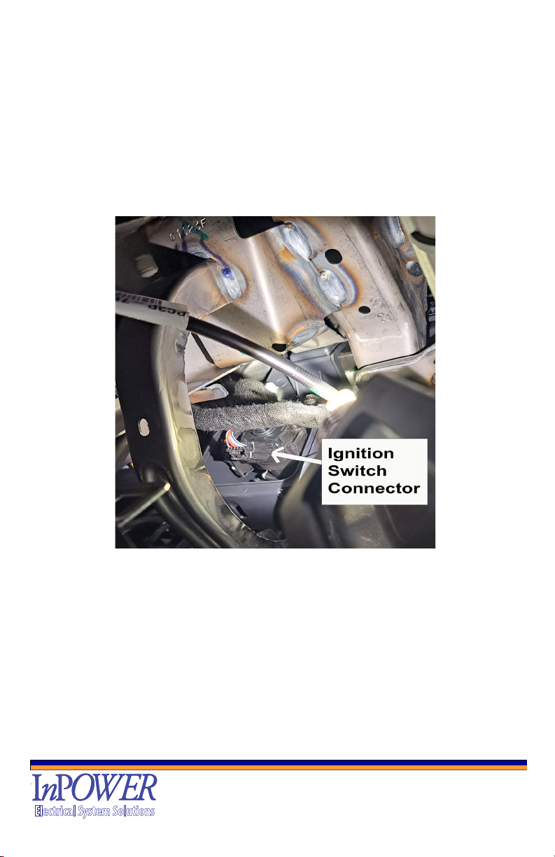
Ignition Switch Connector for IGN T-Harness

SS-FD23 Owner’s Manual
Document: OM-255 Version Code: B
Date: May 31, 2023 Date: Aug 31, 2023
© Copyright 2023 InPower LLC
Page
15 of 16
InPower LLC
8311 Green Meadows Drive
Lewis Center, Ohio 43035 USA
740-548-0965
www.InPowerLLC.com
Electrical System Solutions
Installation of Ignition Switch T-Harness

SS-FD23 Owner’s Manual
Document: OM-255 Version Code: B
Date: May 31, 2023 Date: Aug 31, 2023
© Copyright 2023 InPower LLC
Page
16 of 16
InPower LLC
8311 Green Meadows Drive
Lewis Center, Ohio 43035 USA
740-548-0965
www.InPowerLLC.com
Electrical System Solutions
Contact Us
InPower LLC
8311 Green Meadows Drive
Lewis Center, Ohio 43035
740-548-0965
www.InPowerLLC.com
Table of contents
Other InPOWER Automobile Accessories manuals


Popular Automobile Accessories manuals by other brands

Paxton Automotive
Paxton Automotive Novi Supercharger 1200 Owner's installation guide

Aim
Aim X90BGGK12MA user manual

Well
Well REC-BT-ACCENT-WL instruction manual

Broadfeet
Broadfeet DCNI-523-32 installation instructions

ECS Electronics
ECS Electronics HY-050-DH Fitting instructions electric wiring

ConWys AG
ConWys AG 21020503C Fitting instructions


