InPOWER ITM-133 User manual

Platform Lift Interlock
2006+ Chevy and
GMC GVAN
Model ITM-133
A. Product Description
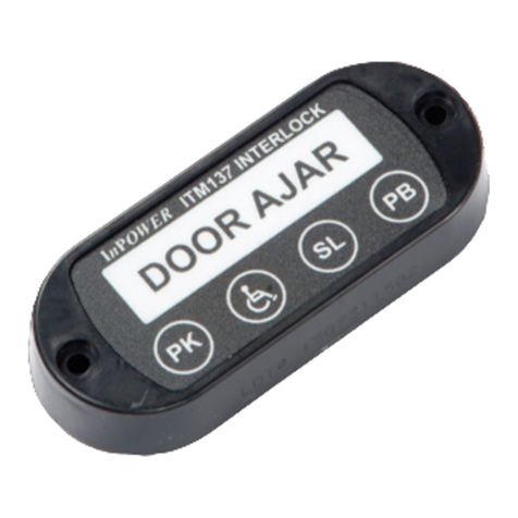
The ITM133 interlock system consists of a control module, remote driver’s LED display,
and chassis interface wiring harness. The control module is a non-microprocessor-
based control device. It contains two connectors for interfacing to the remote LED
display and wiring harness. The “plug and play” GM chassis harness contains two tee-
cables that connect to the parking brake switch and shift lock solenoid that are both
located under the dash. Six 1/4 inch male Faston blade terminals are provided for
interface to the platform lift system, door switch, transmission Park switch, +12 volt
power, and ground.
B. Interlock System Operation
The interlock system is powered from the Interlock Power Switch and the Ignition
Switch when they are both in the On position. The following is the interlock system
sequence of operation:
Step 1 - With the interlock powered on, place the transmission in Park.
Step 2 - Set the parking brake.
Step 3 - Open the lift door. When opened, the transmission shift lock will be set to
prevent the transmission from being taken out of Park, and the Lift Enable will
be set to allow operation of the platform lift. The Lift Door Open light, if
installed, will operate.
Step 4 - The platform lift may now be operated (Refer to the platform lift operating
instructions). Note - During the Lift Enable sequence, if the parking brake is
released the Lift Enable will be deactivated, preventing lift operation.
Step 5 - When the lift cycle is completed return the lift to its fully stowed position.
Step 6 - Close the lift door. Note - Depending on how the door switch is wired, all doors
may need to be closed.
Step 7 - Release the parking brake. When released, the shift lock will automatically
release.
Step 8 - The cycle is now complete and the vehicle can be taken out of Park and
driven.
Notes:
1. The shifter will remain locked in Park whenever the lift door is open.
2. The Lift Door Open output (+12 v @ 2 amps) is activated whenever the door is
open, independent of other interlock inputs.
Continued...
Platform Lift Interlock
2006+ Chevy and
GMC GVAN
Model ITM-133
Electrical System Solutions Electrical System Solutions

InPower Model ITM-133 GM Interlock System
C. Troubleshooting Tips
1. Obtain the appropriate service/maintenance manual from the platform lift
manufacturer (.e.g., Braun, Ricon or Maxon).
2. Obtain the InPower ITM133 interlock system owners manual, document OM-113.
This can be supplied by the vehicle manufacturer that installed the lift and interlock,
or from InPower’s web site, www.InPowerLLC.com.
3. If you experience a problem with the platform lift system, first isolate the problem to
the platform lift or the interlock system.
4. If the interlock system operates properly but fails to release the shift lock at the end
of the cycle (can’t shift out of PARK), the likely cause is an incorrect operation of the
lift door switch or the Park Brake is not released. These inputs to the interlock can
be tested by using the diagnostic LEDs on the ITM133 remote driver’s display (see
InPower Owners manual OM-113 for details).
The Braun Corporation
631 West 11th Street
Winamac, IN 46966
(574) 946-6153
(800) 946-6158
www.braunlift.com
Maxon Lift Corp.
11921 Slauson Avenue
Sante Fe Springs, CA 90670
(562) 464-0099
(800) 227-4116
www.maxonlift.com
D. Reference Information
GM Upfitter Integration
www.gmupfitter.com
Hotline: 800-875-4742
Fax: 586-492-1085
Ricon Corporation
7900 Nelson Road
Panorama City, CA 91402
(818) 267-3038
(800) 322-2884
www.riconcorp.com
InPower Reference:
InPower LLC
8311 Green Meadows Dr.
Lewis Center, Ohio 43021 U.S.A.
Tel: 740-548-0965
Fax: 740-548-2302
Web site: www.lnPowerLLC.com
InPower Model ITM-133 GM Interlock System
C. Troubleshooting Tips
1. Obtain the appropriate service/maintenance manual from the platform lift
manufacturer (.e.g., Braun, Ricon or Maxon).
2. Obtain the InPower ITM133 interlock system owners manual, document OM-113.
This can be supplied by the vehicle manufacturer that installed the lift and interlock,
or from InPower’s web site, www.InPowerLLC.com.
3. If you experience a problem with the platform lift system, first isolate the problem to
the platform lift or the interlock system.
4. If the interlock system operates properly but fails to release the shift lock at the end
of the cycle (can’t shift out of PARK), the likely cause is an incorrect operation of the
lift door switch or the Park Brake is not released. These inputs to the interlock can
be tested by using the diagnostic LEDs on the ITM133 remote driver’s display (see
InPower Owners manual OM-113 for details).
Warranty:
InPower LLC warrants its products to be free from defects in material and workmanship
under normal use, care and maintenance for a period of two years from data of
shipment. Please contact InPower for a copy of our warranty policy and our returns
policy.
For full ITM-133 interlock system product information see InPower Owners Manual,
Document number OM-113.
OM-114B © Copyright 2022 InPower LLC
The Braun Corporation
631 West 11th Street
Winamac, IN 46966
(574) 946-6153
(800) 946-6158
www.braunlift.com
Maxon Lift Corp.
11921 Slauson Avenue
Sante Fe Springs, CA 90670
(562) 464-0099
(800) 227-4116
www.maxonlift.com
D. Reference Information
GM Upfitter Integration
www.gmupfitter.com
Hotline: 800-875-4742
Fax: 586-492-1085
Ricon Corporation
7900 Nelson Road
Panorama City, CA 91402
(818) 267-3038
(800) 322-2884
www.riconcorp.com
InPower Reference:
InPower LLC
8311 Green Meadows Dr.
Lewis Center, Ohio 43021 U.S.A.
Tel: 740-548-0965
Fax: 740-548-2302
Web site: www.lnPowerLLC.com
Warranty:
InPower LLC warrants its products to be free from defects in material and workmanship
under normal use, care and maintenance for a period of two years from data of
shipment. Please contact InPower for a copy of our warranty policy and our returns
policy.
For full ITM-133 interlock system product information see InPower Owners Manual,
Document number OM-113.
OM-114B © Copyright 2022 InPower LLC
Other InPOWER Automobile Accessories manuals
Popular Automobile Accessories manuals by other brands

ULTIMATE SPEED
ULTIMATE SPEED 279746 Assembly and Safety Advice

SSV Works
SSV Works DF-F65 manual

ULTIMATE SPEED
ULTIMATE SPEED CARBON Assembly and Safety Advice

Witter
Witter F174 Fitting instructions

WeatherTech
WeatherTech No-Drill installation instructions

TAUBENREUTHER
TAUBENREUTHER 1-336050 Installation instruction


