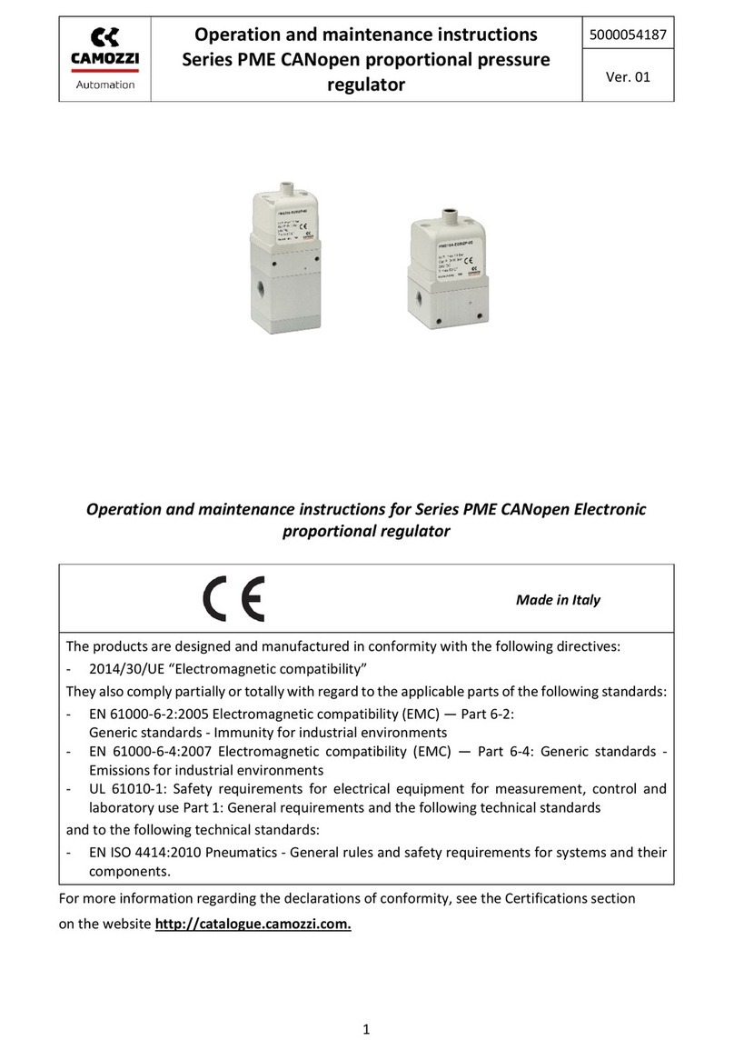
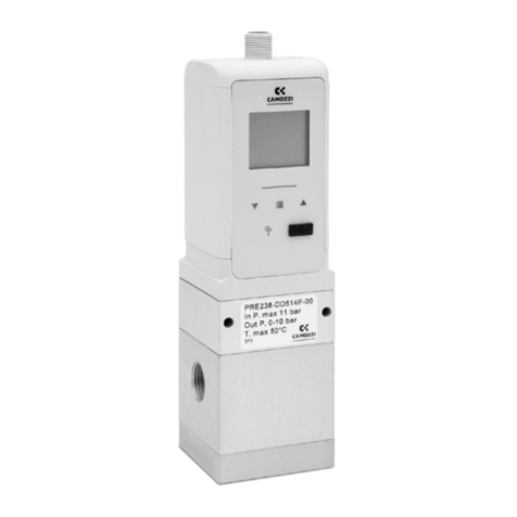
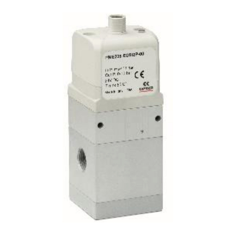
Camozzi ER100 Series User manual

Electro-pneumatic Regulator ER100 Instruction Manual rev. 2.0
page 1 / 38
INSTRUCTION MANUAL
DIGITAL
Electro-pneumatic
Regulator
Series ER100
ANALOG INPUT TYPE
ER104 - x0/1/2xx
PARALLEL INPUT TYPE
ER104-xPxx
• Please read this instruction manual
carefully before using this product,
particularly the section describing
safety.
• Retain this instruction manual with the
product for further consultation
whenever necessary.

Electro-pneumatic Regulator ER100 Instruction Manual rev. 2.0
page 2 / 38
Safety instructions
To use this product safely, basic knowledge of pneumatic equipment,
including materials, piping, electrical system and mechanism, is required
(ISO 4414 *1 JIS B 8370 *2).
We do not bear any responsibility for accidents caused by any person
without such knowledge or arising from improper operation.
This since this product is used in a vast range of applications and
therefore not possible for us to have full knowledge in all of them.
Depending on operating conditions, the product may fail to operate to
maximum performance, or cause an accident. Thus, before placing an
order, examine whether the product meets your application,
requirements, and how to properly use it.
This product incorporates many functions and mechanisms to ensure
safety. However, improper operation could result in an accident. To
prevent such accidents please read this operation manual
carefully for proper operation.
Please observe the cautions on handling described in this manual, as
well as the following instructions:
Additionally, the caution is classified into the following three groups,
“CAUTION”, “WARNING”, and “DANGER”, in order to identify the degree
of the danger it presents and possible hazard.
Failure to pay attention to DANGER notices in extreme
conditions may cause a situation that results in serious
injury or loss of life.
Failure to pay attention to WARNING notices may
result in serious injury or loss of life.
Failure to pay attention to CAUTION notices may result
in injury or equipment damage.
*1) ISO 4414 : Pneumatic fluid power ••• Recommendations for the application of
equipment to transmission and control systems.
*2) JIS B 8370 : General rule for pneumatic systems
DANGER:
!
WARNING:
!
CAUTION:
!

Electro-pneumatic Regulator ER100 Instruction Manual rev. 2.0
page 3 / 38
INDEX
ER100 series Digital Electro-Pneumatic Regulator
ANALOG INPUT TYPE PARALLEL INPUT TYPE
1. DESIGN AND SELECTION······································································································· 4
2. INSTALLATION·······························································································································7
2.1. Option Bracket Installation ·········································································· 9
2.2. Wiring ········································································································ 10
2.3. Connecting the D-SUB·············································································· 15
2.4. D-SUB Connector/Cable - Colour coding ················································16
3. PRODUCTS·····································································································································17
3.1. Parts name ································································································ 17
3.2. Dimensions································································································ 18
3.3. Internal structure ······················································································· 19
4. OPERATION METHOD··············································································································20
4.1. Name and Function of Display/Operation Part ········································· 20
4.2. Function List ······························································································ 21
4.3. RUN Mode – How to operate ···································································· 22
4.3.1. Input Signal Check and Pressure Monitor ········································· 22
4.3.2. Zero- and Span Adjustment ······························································· 23
4.3.3. LED - Auto Power-Off ········································································ 23
4.3.4. Switch Output Function”F4” ······························································· 23
4.3.5. Proportional Value Change Function ”F5” ········································· 24
4.4. Setting Method ·························································································· 25
4.4.1. Input Signal Setting············································································ 25
4.4.1.1. Analog Type Input Signal Selection············································ 25
4.4.1.2. Parallel Type Input Signal Selection ··········································· 26
4.4.1.3. Preset memory Input Setting······················································ 26
4.4.1.4. Direct Memory Input Setting······················································· 26
4.4.2. Zero- and Span Settings ···································································· 27
4.4.3. Auto Power-Off Setting ······································································ 27
4.4.4. Switch Output Setting ········································································ 28
4.4.5. Proportional Value Change································································ 29
4.5. Key Lock···································································································· 30
4.6. Setting Range of Each Function ······························································· 31
4.7. Return to factory Settings (Reset)····························································· 32
5. MAINTENANCE····························································································································33
5.1. Error Code································································································· 34
5.2. Troubleshooting························································································· 35
6. SPECIFICATIONS AND PRODUCT CODE·····································································37
6.1. Specifications ER-104-5* e ER-104-9* ····················································· 37
6.2. Specifications ER-104-1* ·········································································· 38
6.3. How to order······························································································ 39
6.4. Optional individual code ············································································ 40
7. REFERENCE··································································································································42
7.1. Relationship between parallel type input signal and control pressure ······ 42
7.2. Relationship between preset memory and input signal ···························· 42

Electro-pneumatic Regulator ER100 Instruction Manual rev. 2.0
page 4 / 38
1. DESIGN AND SELECTION
• Supply only “compressed air”.
• For compressed air, always use clean air that does not contain corrosive
gas.
• Be sure to use non lubricated, filtrated dry air (equivalent to Class 1, 3,
2 – ISO 8571-3).
• With a thorough understanding of compressed air characteristics, design
a pneumatic circuit.
・Where instantaneous stop holding at emergency stop is required, the
same function as in the mechanical or hydraulic or electrical units cannot
be expected.
・There arise pop-up, jet-out and leaking phenomena caused by
compressibility and expansibility, which are air characteristics.
• Prior to use, always ensure that the product withstands the operating
environment.
・The product cannot be used in corrosive gas, chemical liquid solvent,
water, water vapour (steam) and ozone atmosphere. When a product is
exposed to water droplets, oil or metallic powder, such as spatters and
chips, be sure to protect it.
・No product can be used in the explosive gas atmosphere.
• Always pay extra attention to the electric circuit during emergency stop,
and cylinder operation, etc. during power failure.
• Attach a “pressure switch” and “residual pressure discharge valve” to
the compressed air inlet of the equipment.
・The pressure switch controls operation so that it cannot be carried out
where the set pressure is not reached.
The residual pressure discharge valve discharges compressed air
remaining inside the pneumatic circuit, to prevent accidents caused by
pneumatic equipment operation due to residual pressure.
• If the product is left as it is with the supply pressure when no power is
turned ON, the secondary side pressure may increase up to the supply
pressure.
If any concerns regarding safety; take proper safety measures in the
system; for example, use an extra valve on inlet or outlet.
• Use the product correctly at the indicated working pressure range.
• Note the maintenance conditions clearly in the equipment instruction
manual.
・The functionality of the product may be significantly reduced, depending
on the operating condition, operating environment and maintenance
situation, thereby safety might not be secured. If this maintenance
work is conducted accurately and correctly, it is possible to maintain a
sufficient product functionality and performance.
• Use a constant voltage power supply.
• Check the leak current to avoid a malfunction caused by such leakage
from other control equipment.
・The ER may show malfunction under the influence of leak current when
a programmable controller or the like is used.
In case of 24 V DC: 1.8mA or less
• The response time is affected by the supply pressure and load capacity.
When stable response time is required, install an extra pressure
regulator before the Electro – Pneumatic pressure regulator Series ER.
!
WARNING
:
!
CAUTION
:

Electro-pneumatic Regulator ER100 Instruction Manual rev. 2.0
page 5 / 38
• To avoid malfunction caused by electrical noise:
・Insert a line filter into the AC power line.
・Use a surge suppresser like a CR or diode on the inductive load
(solenoid valve, relay and so on) to remove any noise on the source.
・Keep cables connected to this product as far away as possible from
power line.
・Use a shielded cable to connect a device.
・The shielded wire should be grounded on the power supply side.
・Wire the power line as short as possible.
・Don’t share the power with devices that generate the noise, such as
inverter motor.
・Avoid to wire the power line or input signal line in parallel with other
lines.
• When the current input type is wired, the power ground and signal
common are shared.
・When driving several electro pneumatic regulators with one PLC and D/A
-unit, depending on the D/A-unit circuit, this wiring could cause some
malfunction on the input signal. Consult your PLC maker and check
whether it is possible to do this type of wiring or not.
• The current input type can be used with input signal 1 to 5V, but as
opposed to other voltage input types, the input impedance is small
(250Ω). Use an appropriate voltage generator.
• Please observe that bad air quality affects its characteristics,
functionality and durability in a negative way.
・ For the pneumatic source, use cleaned air from which the solids,
water and oil contents were eliminated sufficiently, using an air dryer,
filter and oil mist filter.
Do not use lubricated air as it may compromise the characteristics
and functionality.
Air filter
5µm
Air drye
r
Oil mist filte
r
(oil removing)
Pressure switch
Regulator
・When the secondary pressure is reduced with an input signal, etc.,
secondary air passes through the product inside and is discharged from
the main exhaust port (EXH). Contamination of secondary piping and
the inside of the load will therefore compromise the characteristics and
functionality etc. Keep the inside of the piping as clean as possible.
• If the power is turned off under pressure, the secondary pressure is
held at its last value. However, this maintained pressure is not
guaranteed to last for very long.
・In this case, if you need to exhaust the secondary side, reduce the
control pressure by reducing the control voltage/current first and then
turn off the power or use the exhaust valve.
• Since the supply pressure is supposed to provide the exact control
pressure, it is important for the working pressure not to drop below “set
secondary pressure + 0,5 Bar ” for model ER104-1* or drop below “set
secondary pressure + 1 Bar ” for all other models.
・N.B. If the supply pressure is not supplied for a long time while power is
ON, product life is reduced. Avoid therefore this type of use.
!
CAUTION
:

Electro-pneumatic Regulator ER100 Instruction Manual rev. 2.0
page 6 / 38
• When the secondary side control pressure is used with the port left
open (in applications using nozzles for blowing etc.), pressure
fluctuations may occur depending on the piping conditions and the blow
conditions. Though it requires some extra efforts, please either verify
via testing using the actual use conditions or consult Camozzi.
• When selecting a dryer, air filter, oil mist filter or regulator, select a
device with a flow rate higher than that used by proportional pressure
controls.
• Operating environment
・Avoid operating the product in places where it may be affected by direct
sunlight, water or oil.
For operation in other than the specification requirements or for special
purposes, please contact Camozzi.
• Drip-proof environment
・The protective structure of this product is equivalent to that of
the IP40. Do not install this product at places where exposed to
moisture, salt, dust or chips or under positive or negative pressure. Do
not operate at places with steep temperature fluctuations or in high
humidity because dew condensation inside the main body will cause
problems.
• With this product, even if the pressure is set to 0 bar, the secondary
pressure is not completely released. It remains at a value less than 1%
of F.S. of maximum control pressure. If 0 Bar is required, bleed the
secondary side, or install a 3/2-way valve on the secondary side to
switch to atmosphere, etc.
!
CAUTION
:

Electro-pneumatic Regulator ER100 Instruction Manual rev. 2.0
page 7 / 38
2. INSTALLATION
• Keep a sufficient space for operation & re-installation, wiring and piping
work around the product.
• Provide a pneumatic filter just in the pre-stage of the circuit in which
the pneumatic equipment is used.
• IMPORTANT. Do never block the exhaust port. Always reserve space
necessary for exhaust air.
• The rotation mechanism of the D-sub connector is not to be considered
as a flexible joint for moving units (continuous oscillation). Use at either
the top or side position (do not use at an angle in between), and fix the
cable if the cable moves.
() ( ) (×)
• Do not detach the port seal until piping work is started.
・If the port seal is removed before piping work, dirt may enter into the
interior from the piping port, thus causing trouble and malfunctions, etc.
• Sufficiently flush/blow air pipes before connecting to the Electro-
pneumatic regulator Series ER. Check that sealing tape is not caught
when piping.
• When applying a seal tape, start from a position 2-mm or more away
from the end of the thread portion on the tube, to a direction opposite
to the tip of the tube, and wind the tape around the tube in a direction
reverse to the direction of the thread.
・If a part of the seal tape is positioned closer to the tip of the tube than
the thread portion, the tape may be threaded into pieces as the tube is
screwed into the joint; they may go into the pneumatic equipment and
cause trouble.
Pilot exhaust ai
r
Main exhaust air
5mm or more
Wall
!
CAUTION
:

Electro-pneumatic Regulator ER100 Instruction Manual rev. 2.0
page 8 / 38
Solid and
liquid sealant
Solid and
liquid sealant
Seal Ta
p
e Solid and li
q
uid sealant

Electro-pneumatic Regulator ER100 Instruction Manual rev. 2.0
page 9 / 38
• Correct pressure control is not possible if the exhaust port is plugged.
Always keep this port in contact with the atmosphere.
• Tighten pipes with the appropriate torque force.
・Pipes must be connected with the appropriate torque force to prevent
air leakages and screw damage.
・First tighten the fitting by hand to prevent damage to the threads, then
use a tool.
RRecommended tightening torque
Port screw Tightening torque N⋅m
G1/4 6 to 8
• When supplying compressed air after connecting pipes, check that high
pressure is not supplied instantly.
• Before supplying compressed air after connecting pipes, check that that
there are no air leaks at any pipe connections.
・If necessary, apply leakage detection fluid onto pipe connections, and
check for air leaks.
2.1. Option Bracket Installation
Use the mounting screws which come with the bracket, to fix on the bottom face of the main body.
* For the option bracket, refer to Section 6.3 “Optional individual code”.
Cross headed pan
machine screw
with spring retainer M3×8
(4 screws/attached)
B1-type can be installed in both directions.
B1 type bracket
(Attached option: -B1)
B2 type bracket
(Attached option: -B2)
!
CAUTION
:

Electro-pneumatic Regulator ER100 Instruction Manual rev. 2.0
page 10 / 38
2.2. Wiring
• When performing wiring, check the connector pin and cable
conductor colour when connecting a cable.
Connection of a wrong cable may cause breakage, failure or
malfunction.
• Check if the wiring is properly insulated.
・Avoid contacting other circuits, ground faults, and terminal-to-terminal
continuity.
This could an excessive current (short circuit), possibly causing
breakage.
• Use a rated DC regulated power supply isolated from the commercial
alternating current power source. A non-isolated power supply may
cause electric shock.
With an unregulated power supply, the peak value may exceed the
maximum rating, causing breakage of this product or poor accuracy.
• Stop the controllers and mechanical equipment and turn the power
off before connecting wiring.
Sudden activation may cause unexpected actions, possibly causing
danger.
First, while leaving controllers and mechanical equipment stopped,
perform a power-on test. Discharge static electricity from human
bodies, tools and equipment before and during work. Connect a
flexible cable, such as the one for robots, to moving parts.
• Do not exceed the source voltage range during operation. An
excessive voltage or an alternating current power supply (100VAC)
will cause damage or fire.
• Do not short-circuit the load since this may cause damage or fire.
• The optional shield cable connector is a shield wire.
・When not using the wire, insulate so that there is no contact with
other wires (including the shield wire).If missconnecting wires to the
ground, it will lead to malfunction or destroy the product.
!
WARNING
:
!
CAUTION
:

Electro-pneumatic Regulator ER100 Instruction Manual rev. 2.0
page 11 / 38
< Internal circuit and connection >
[Analog input type ER]
• Product code-AN: Analog output + Error<NPN>Output type
[Analog input type ER]
• Product code-SN: Switch output<NPN> + Error<NPN>Output type
M
a
i
n
c
i
r
c
u
i
t
output
pro-
tection
circuit
Signal
generator
max50mA
Load
5 pi n(Power+)
11 pin(analog input)
1 pi n
(preset bit1)
2 pi n
(preset bit2)
3 pi n
(preset bit3)
10 pin(common)
13 pin(monitor output)
14 pin(error ou tput)
15 pin(Power-)
Load
+
-
out
p
ut
p
ro-
tection
circuit
5 pin(Power+)
11 pin(analog input)
1 pin
(preset bit1)
2 pin
(preset bit2)
3 pin
(preset bit3)
10 pin(common)
13 pin(switch output)
14 pin(error output)
15 pin(Power-) max50mA
max50mA
Si
g
nal
g
enerator
Load
Load
+
-
M
a
i
n
c
i
r
c
u
i
t

Electro-pneumatic Regulator ER100 Instruction Manual rev. 2.0
page 12 / 38
[Analog input type ER]
• Product code-AP: Analog output + Error<PNP>Output type
[Analog input type ER]
• Product code-SP: Switch output<PNP> + Error<PNP>Output type
5 pin(Power+)
11 pin(analog input)
1 pin(preset bit1)
2 pin(preset bit2)
3 pin(preset bit3)
10 pin(common)
13 pin
(monitor output)
14 pin
(error output)
15 pin(Power-)
max50mA
out
p
ut
p
ro-
tection
circuit
Load Load
Si
g
nal
g
enerator
+
-
M
a
i
n
c
i
r
c
u
i
t
5 pin(Power+)
11 pin(analog input)
1 pin(preset bit1)
2 pin(preset b it2)
3 pin(preset b it3)
10 pin(common)
13 pin
(switch output)
14 pin
(error output)
15 pin(Power-)
max50mA
max50mA
out
p
ut
p
ro-
tection
circuit
Si
g
nal
g
enerator
Load Load
+
-
M
a
i
n
c
i
r
c
u
i
t

Electro-pneumatic Regulator ER100 Instruction Manual rev. 2.0
page 13 / 38
[PARALLEL input type ER]
• Product code-AN: Analog output + Error<NPN>Output type
[PARALLEL input type ER]
• Product code-SN: Switch output<NPN> + Error<NPN>Output type
[PARALLEL input type ER]
5
p
in
(
Powe
r
+
)
13
p
in
(
monitor out
p
ut
)
14
p
in
(
error out
p
ut
)
15
p
in
(
Power-
)
max50mA
10
p
in
(
common
)
+
-
Load Load
out
p
ut
p
ro-
tection
circuit
12 pin(MSB bit10)
11 pin(bit9)
9 pin(bit8)
8 pin(bit7)
7 pin(bit6)
6 pin(bit5)
4 pin(bit4)
3 pin(bit3)
2 pin(bit2)
1 pin(LSB bit1)
M
a
i
n
c
i
r
c
u
i
t
out
p
ut
p
ro-
tection
circuit
5
p
in
(
Po wer+
)
13
p
in
(
switch out
p
ut
)
14
p
in
(
error out
p
ut
)
15
p
in
(
Powe
r
-
)
max50mA
max50mA
10
p
in
(
common
)
+
-
Load
Load
12 pin(MSB bit10)
11 pin(bit9)
9 pin(bit8)
8 pin(bit7)
7 pin(bit6)
6 pin(bit5)
4 pin(bit4)
3 pin(bit3)
2 pin(bit2)
1 pin(LSB bit1)
M
a
i
n
c
i
r
c
u
i
t

Electro-pneumatic Regulator ER100 Instruction Manual rev. 2.0
page 14 / 38
• Product code-AP: Analog output + Error<PNP>Output type
[PARALLEL input type ER]
• Product code-SP: Switch output<PNP> + Error<PNP>Output type
5 pin(Power+)
13 pin(monitor output)
14 pin(error output)
15 pin(Power-)
max50mA
10 pin(common)
Load Load
+
-
out
p
ut
p
ro-
tection
circuit
12 pin(MSB bit10)
11 pin(bit9)
9 pin(bit8)
8 pin(bit7)
7 pin(bit6)
6 pin(bit5)
4 pin(bit4)
3 pin(bit3)
2 pin(bit2)
1 pin(LSB bit1)
M
a
i
n
c
i
r
c
u
i
t
5 pin(Power+)
13 pin(switch output)
14 pin(error output)
15 pin(Power-)
max50mA
out
p
ut
p
ro-
tection
circuit
max50mA
10 pin(common)
Load
Load
+
-
12 pin(MSB bit10)
11 pin(bit9)
9 pin(bit8)
8 pin(bit7)
7 pin(bit6)
6 pin(bit5)
4 pin(bit4)
3 pin(bit3)
2 pin(bit2)
1 pin(LSB bit1)
M
a
i
n
c
i
r
c
u
i
t

Electro-pneumatic Regulator ER100 Instruction Manual rev. 2.0
page 15 / 38
2.3. Connecting the D-SUB
• Insert the D-sub connector to the socket securely.
• The D-sub connector has a mechanism for turning 90°. When
connecting the D-sub connector, insert it at the top or side position
while holding it securely in the hand.
• Lock the D-sub connector so that it does not come off.
To unlock, hold the fixing base with a wrench or similar while
unscrewing with a screwdriver.
<Connector pin array>(Product body side)
Refer to Section 2.4 “Connecting” for the wiring method.
No pin is provided for the analog input type at positions marked
!
CAUTION
:
Wrench
Screwdriver
Insert the connector
while holding it securely
in the hand.

Electro-pneumatic Regulator ER100 Instruction Manual rev. 2.0
page 16 / 38
2.4. D-SUB Connector/Cable - Colour coding
• Check the product code and take sufficient care of connection.
• Handle the unused monitor output, switch output or preset input so
that it does not make contact with other cables (including the
shield).
• Ground the shield wire on the power (-) side.
[Analog input type ER]
D sub socket
pin No.
1 2 3 4 5
6~910 11 12 13 14 15
Option cable
isolator color Brown
Orange
Yellow
-
Red
-
Gray White
-
Green Blue Black
Preset input signal Power
+ Input signal
Monitor
output
Switch
output
Error
output
Type of input
1 bit 2 bit 3 bit
N/A
+24
VDC
N/A
Common
0
-
10
VDC
0
-
5V
DC
4
-
20
mADC
N/A
Output
1-5VD
C
NPN
or
PNP
output
NPN
or
PNP
output
Power
-
(0V)
[PARALLEL input type ER]
D sub socket
pin No.
1 2 3 4 5 6 7 8 9 10 11 12 13 14 15
Option cable
isolator color Brown
Orange
Yellow Purple Red Pale
blue Pink
White
(
with
black
line
)
Red
(
with
black
line
)
Gray White
Green
(
with
black
line
)
Green Blue Black
Name
Parallel input signal Power
+ Parallel input signal
Parallel input
signal
Monitor
output
Switch
output
Error
output
Type of input
1 bit 2 bit 3 bit 4 bit +24
VDC 5 bit 6 bit 7 bit 8 bit
Common
9 bit 10 bit
Output
1-5VD
C
NPN
or
PNP
output
NPN
or
PNP
output
Power
-
(0V)
POSSIBLE COLOUR MODIFICATIONS WILL BE INDICATED ON THE CABLE’S
PACKAGING
!
CAUTION
:

Electro-pneumatic Regulator ER100 Instruction Manual rev. 2.0
page 17 / 38
3. PRODUCTS
• Use the specified voltage for the source voltage and output.
If an excessive voltage is connected, malfunction, breakage of the
sensor, electric shock and/or fire may be caused. Also, do not use loads
exceeding the output rating, since this may cause damage of the output
or fire.
3.1. Parts name
!
DANGER
:

Electro-pneumatic Regulator ER100 Instruction Manual rev. 2.0
page 18 / 38
3.2. Dimensions

Electro-pneumatic Regulator ER100 Instruction Manual rev. 2.0
page 19 / 38
3.3. Internal structure
No. Name of parts Materials
1 Plate Resin
2 D sub connector -
3 Housing Resin
4 Controller substrate -
5 Poilot valve -
6 Valve base Polyphenylen sulfite resin
7 Pilot chamber Polyphenylen sulfite resin
8 Body Aluminium alloy die-casting
9 Pressure sensor -
10 Diaphragm Special nitrile rubber
11 Relief seat Aluminium alloy
12 Steel ball (Exhaust port) Stainless steel
13 Valve Special nitrile rubber, Stainless steel
14 Bottom rubber Silicone rubber
15 Bottom plug Brass, Chemical nickel plating
16 O ring Fluoro rubber
1
2
3
4
5
6
7
9
10
11
12
13
14
15
16
8

Electro-pneumatic Regulator ER100 Instruction Manual rev. 2.0
page 20 / 38
4. OPERATION METHOD
• This product does not conduct pressure control during around two
seconds while carrying out self diagnosis immediately after it is turned
on. Therefore build a control circuit or program to ignore signals for
about two seconds immediately after power-on.
• To change output settings, stop the equipment to avoid unintended
actions caused to the equipment in the control system.
4.1.
Name and Function of Display/Operation Part
Output display (red)
“F” is displayed during function setting.
“-” is lit when the switch output is ON.
(Only for switch output specification)
* The bar blinks upon detection of an
excessive current (short circuit).
“E” lights when error output is ON.
* The letter blinks upon detection of
an excessive current.
* If there is an upper or lower limit in the function setting,
one of the following is displayed.
or
key
Use the key to start various setting
modes.
Use the key to set a value during data
entry.
key
Use the key to select the digit to be changed
during data entry.
3-digit numerical LED display (green)
In the RUN mode (pressure display), the pressure or
function setting data is displayed.
* In the function setting data display mode, the setting
mode number and setting are displayed.
During data entry, a value or other types of data are
displayed.
Upon error display, the error code number is displayed.
< During pressure display > < During setting display >
< Error output display>
key
Use the key in the RUN mode
(pressure display), to display various
settings one by one.
Use the key to select a setting item
during data entry.
Use the key to increase/change the
value or the like during data entry.
!
CAUTION
:
Code number
Setting
method
Setting mode
number
This manual suits for next models
11
Table of contents
Other Camozzi Controllers manuals