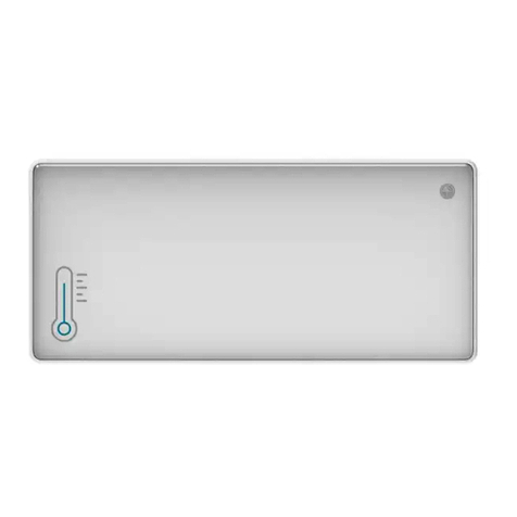
INSBUD IB-TRON 1000 GWC User manual

Electronic controller
to control Ground Heat Exchanger
IB – Tron 1000 GWC

InsBud company supports policy of development. The right to making changes and
improvements in products and manuals without prior notice reserved!
The contents of this manual - the text and graphics are owned by InsBud company
or its subcontractors. It is legally protected.
Products is marked
and has been produced in accordance with ISO 9001 standard
v1.2
„INSBUD”
ul. Niepodległości 16a
32-300 Olkusz
POLAND
sales department: +48 (32) 626 18 00
sales department: +48 (32) 626 18 18
technical department: +48 (32) 626 18 07
technical department: +48 (32) 626 18 08
fax: +48 (32) 626 18 19
e-mail: [email protected]

www.insbud.net 3
ENGLISH
Contents
IB-TRON 1000 GWC
Basic information __________________ 4
Features _________________________ 4
Technical data_____________________ 5
Available models __________________ 5
Scope of delivery __________________ 5
General considerations _____________ 5
Structure _________________________ 6
LCD Display_______________________ 7
Connection _______________________ 7
Temperature sensors _______________ 8
Operating principle ________________ 8
Example of operating_______________ 9
Exemplary connection diagram ______ 10
Example of Controlling by Water Heat
Exchanger ________________________ 11
Calibration _______________________ 12
Clock ____________________________ 12
Clock displaying ___________________ 12
Day of the week ___________________ 12
Temperature units _________________ 12
Work mode _______________________ 13
Test period and test break ___________ 13
Hysteresis ________________________ 13
Keyboard lock_____________________ 13
GUARD function ___________________ 14
Factory settings ___________________ 14
Test of relays ______________________ 14
Modes of temperature displaying _____ 14
Software version___________________ 15
Network communication ____________ 15
Errors____________________________ 15
Remote Control ___________________ 16
Warranty _________________________ 16

www.insbud.net
4
ENGLISH
BASIC INFORMATION FEATURES
IB-Tron 1000 GWC controller is indepen-
dent microprocessor controller with large
LCD display. The controller is designed to
control work of valves, air dampers, electric
air heaters, pumps, fans and other two- and
three-point controlled appliances (on/o).
IB-Tron 1000 GWC controller allows to con-
trol process of heating, cooling and ventila-
tion. The thermostat chooses source of heat
or cold in intelligent way including testing
periods. An example of this type of installa-
tion is controlling of ground heat exchanger
(GHE).
A professional and intelligent controller
to control systems where you have to cho-
ose source of heat or cold from two die-
rent sources! This is not a simple dierential
controller!
Large, blue backlit (optional) LCD di-
splay which shows current tempe-
rature, a day of the week and other
information.
Easy, intuitive operating and
programming.
Measurement of two temperatures T1
and T2
Power supply from network - it doesn’t
reguire batteries - with baterry memory
backup
Displayed temperature with 0,1 ºC
accuracy
Esthetic and modern design
Large load - to 2 kW - allows to direct
connection most of electrical applian-
ces without the use of contactor.
The possibility of calibrate device
(external sensors on long wires, inde-
pendent calibration of T1 and T2)
Adjustable hysteresis
Testing periods of devices to measure
Heating mode (winter) and cooling
mode (summer)
GUARD function - protection devices
from damage
TEST function
Network, RS - 485 or Ethernet commu-
nication (optional)
The possibility of remote control
(optional)
Keyboard lock

www.insbud.net 5
ENGLISH
TECHNICAL DATA SCOPE OF DELIVERY
GENERAL CONSIDERATIONS
AVAILABLE MODELS
Energy consumption: < 2 W
Storage temperature: -5 ÷ 50 ºC
Displayed temperature: -20 ÷ 140 ºC
every 0,1 ºC
Accuracy: 1 ºC
Hysteresis: 1 ÷ 5 ºC
Test breaks: 1 ÷ 999 min.
Test period: 0 ÷ 999 sec.
Maximum load: 2000 W
Power supply 230V AC
Casing: ABS
Dimensions [mm]: 120x120x23
Display: LCD (4``)
Control: Electronic
Protection rating: IP30
Battery settings protection:
» 36 months
1x Controller (the main panel)
1x Relay box
1x Built-in temperature sensor
1x Operating manual
1x Operating manual for network (only
with NW model)
1x Pilot of remote control with battery
(only with RC model)
HDuring installation of controller, the
supply of electricity should be turned
o. It’s recommended to entrust the in-
stallation a specialized institution.
The controller is for surface-mounting,
it sticks out 23mm.
In the controller a relay box is separa-
tely on the 20cm wire and dimensions
30/50/65mm
IBuilt-in RT sensor is complete with
thermostat. FT sensor isn’t supplied
with thermostat.
RT sensor is on the 20cm wire and it can
be bring out at the back of casing.
IRT sensor can be extended according
to needs or it can be replaced by ano-
ther type of sensor (if it’s needed).
IChange of RT sensor doesn’t invalidate
the warranty.
HThe controller gives 230V voltage on
the output (support of pump, valve, air
damper, heating mat etc.). If thermostat
has to operate normally open/normally
closed device, so-called: contact device
(for example: gas heating stove), it will
be required additional normally open/
normally closed relay. Wa have these re-
lays in our oer.
BL - blue backlight (backlight is activa-
ted by pressing any button and deacti-
vated after a certain period of inactivity)
RC - IR remote control
NW - thermostat to work in the network
(RS-485 or Ethernet communication)

www.insbud.net
6
ENGLISH
STRUCTURE
PROG
MODEL
TIME
RT SENSOR
DAY
HEATING
COOLING
DEL
CANCEL THE
ENTERED DATA
MODE
PLUS MINUS
ENTER

www.insbud.net 7
ENGLISH
LCD DISPLAY
CONNECTION
A DAY OF THE
WEEK HOUR
TEMPERATURE/
SETTING
MODE OF
DISPLAYING
WORKIDENTYFICATION
OF SENSOR
NETWORK
HEATING
(WINTER)
COOLING
(SUMMER)
KEYBOARD
LOCK
AM
PM
NET
RT
FT MODEL AF
1 - 2 FT sensor
3 - 4 power supply 230V AC
5 A phase appears (L) when cho-
osing FT source
6 A phase appears (L) when cho-
osing RT source
Two loose wires with thermistor come
out from the controller, it can be cut
and connect external RT sensor

www.insbud.net
8
ENGLISH
TEMPERATURE SENSORS OPERATING PRINCIPLE
IComplete with controller is NTC thermi-
stor on the 20cm wire. It can function
as a one sensor if there isn’t required an
additional casing of sensor. The second
sensor isn’t supplied with termostat.
IThe sensors can be extended to any
length but we should remember that
extension above 10m may cause a de-
viation of measurement with each me-
ter and falsifying results. Therefore, for
distance above 10m device has to be
calibrated. Sensors have to be extend
of wires:
» to 50 meters 2x 0,75 mm2
» above 50 meters 2x 1,50 mm2
The controller is compatible with NTC
10kΏ sensors having the following
characteristics:
Temperature
[ºC]
Resistance
[Ώ]
-50 687 803
-40 346 405
-30 181 628
-20 99 084
-10 56 140
0 32 960
10 20 000
20 12 510
25 10 000
30 8 047
40 5 310
50 3 588
60 2 476
70 1 743
80 1 249
90 911
100 647
In the controller we have to set three time
values:
Testing break - value in minutes spe-
cifying, at what time do the measuring
test. This value depends on devices,
which ‘receive’ heat or cold and more
precisely depends on how often the
temperature conditions may change
in this device. In the typical size of GHE
(typical family house) this value is most
in the range of 10 ÷ 30 minutes.
Testing periods - value in seconds spe-
cifying, how long device has to work
before reading of sensor reaches the
appropriate level of temperature (star-
ting period, starting delay ). Testing pe-
riod is set separately for each device.
In case of installation of GHE the rst devi-
ce is directly external inlet probe and sensor
has to be placed near to the inlet probe (di-
rect measurement of external temperature).
Testing period of this device should be set
to 0 (there isn’t any delay, the reading is cur-
rent). The second device is GHE. Delay of this
device should be set to optimal value for the
GHE - mostly it’s time to move air through
the GHE (it depends on length and size of
GHE). For the typical size of GHE (for typical
family houses) this delay is in the range of 20
÷ 120 seconds.
Depending on the mode in which the con-
troller operates (heating or cooling), device
chooses warmer or colder device.
The controller is intelligent. It means that it
remembers readings and change the tem-
peratures on the both devices. For example:
when controller during data analysis deter-
mines that there is probability of more favo-
rable temperature conditions on the second
device than currently used device, may be

www.insbud.net 9
ENGLISH
OPERATING PRINCIPLE
EXAMPLE OF OPERATING
EXAMPLE OF OPERATING
to be higher than the air temperature
from the GHE, the controller will switch
devices so that the air was taken from
the external inlet probe (it happens
immediately because testing period of
inlet probe is set on 0 seconds but inc-
luding hysteresis).
If the outside temperature falls below
the last memorized temperature which
was on the GHE or from the appropriate
algorithm, the controller„suspects”that
air temperature from the GHE will be hi-
gher than outside temperature or 15mi-
nutes (testing break)have passed since
the last switching air dampers. The GHE
is turning on (on thirty-seconds testing
period). After the test, the controller
decides from where take the air.
IIn our oer are available air dam-
pers with actuators with dierent
cross-section.
earlier testing of the second device.
Typical GHE installation. The controller is de-
signed to decide from where take the air:
from the GHE - there is closing of the air
damper with actuator from the exter-
nal inlet probe. The air damper with ac-
tuator is opening from the GHE simul-
taneously and the controller starts the
GHE fan.
from the external inlet probe - there
is closing of the air damper with ac-
tuator from the GHE and turning o
the GHE fan. The air damper with ac-
tuator is opening from the inlet probe
simultaneously.
Testing period of inlet probe is set on 0 se-
conds (current measurement without delay).
RT sensor is placed near external inlet probe
so as to measure the outside air temperature
(shady, sheltered from the wind and moistu-
re place).
Testing period of GHE is set on 30 seconds
(this is air ow from the onlet probe of GHE
to recuperator). FT sensor is placed in the
ventilation duct from the GHE before the
recuperator.
Testing break is set on 15 minutes.
Heating mode is set (selection of a hotter
heat source). In the summer the controller
by pressing single button switches onto the
cooling mode to cooling the building.
Exemplary logic of device operating:
The air is taken from the GHE.
When the outside temperature is found

www.insbud.net
10
ENGLISH
EXEMPLARY CONNECTION DIAGRAM
RT
sensor
External inlet
Used, warm air
Used, cold air
Fresh, warm air
Outside
GHE
FT
sensor
P1
P2
sn
B
ud
IB-Tron 1000GWC
2
3
1
4
5
6
Sensor
FT
Sensor
RT
L
N
14 1424 24
11 11
12 12
21 21
22 22
A2 A2
A1 A1
repeater
repeater
np.IB-F200
np.IB-F200
P 1
P2
G.W.C
Brown(open)
Brown(open)
Green (closed)
Green (closed)
Black
Black
Red
Yellow
Pe
Pe
21
2422
11
14
12
A2
A1
21
14
12
pin diagram of relay base
Air damper
Air damper
Power 230V AC
Closing signaling
Closing signaling

www.insbud.net 11
ENGLISH
EXAMPLE OF CONTROLLING WATER HEAT EXCHANGER
IB-Tron 1000 GWC controller measures two temperatures: outside temperature (by RT sen-
sor) and air temperature after passing through the heater, when water circulation pump is
turned on (glycol or brine), by FT sensor. Measurement of the outside temperature (RT) is
current, measurement of air temperature (FT) at the switching on heater has to be cyclic.
Testing period should be as short as possible but has to ensure proper stabilization of the
air temperature after passing through the heater (installation which leads water, heater and
air from the heater has to warm up).
If the controller after this testing period recognizes that favorable temperature conditions
provides water heat exchanger, the pump still works and measurement of FT temperature
is current. Measurement of RT temperature is current too, so if favorable temperature con-
ditions are at the external inlet probe, the P1 pump will be turned o.
If favorable temperature conditions after testing period are still at the external inlet probe,
P1 pump is turned o. The pump is again turned on only after testing period.
Bottom source
P1
FT
Sensor
RT
Sensor
sn Bu d
IB-Tron 1000GWC
2
3
1
4
5
6
FT
Sensor
RT
Sensor
Power 230V AC
L
N
Pump P1
1
2
Fresh, warm air
Used, warm air
Used, cool air
Fresh, cold air
Outside

www.insbud.net
12
ENGLISH
CALIBRATION
ZEGAR
TEMPERATURE UNITS
CLOCK DISPLAYING
DAY OF THE WEEK
After proper connection the controller is re-
ady to work. The controller is factory calibra-
ted to work with standard sensor. However,
with long wires, displayed temperature may
be dierent from real temperature.
In this case you have to calibrate the device
by yourself.:
A clock doesn’t aect to controller work. It’s
only information.
To set current hour please:
Temperature can be displayed in ºC and ºF
To change units please:
Time can be displayed in 24-hour system or
12-hour system.
To change mode of time displaying please:
Day of the week doesn’t aect to controller
work. It’s only information.
To set current day of the week please:
DEL
TIME
DAY
DAY
PROG
TIME
MODE
+
+
+
-
-
-
Press and hold. On display start a-
shing current value of the calibra-
tion settings and kind of sensor.
By repeatedly pressing button you
can change calibrated sensor.
Press and hold. On display start
ashing current value of the clock
settings.
Press the button. On display start
ashing a day of the week.
Press for 3 seconds both buttons.
Press and hold two buttons for 3
seconds.
Calibrate sensor by setting the ap-
propriate value settings.
Set current hour (longer holding
the button will faster change
time)
Set current day of the week
» MON - Monday
» TUE - Tuesday
» WED - Wednesday
» THU - Thursday
» FRI - Friday
» SAT - Saturday
» SUN - Sunday
Conrm the data.
Conrm the data.
Conrm the data.

www.insbud.net 13
ENGLISH
WORK MODE HYSTERESIS
KEYBOARD LOCK
TEST PERIOD AND TEST BREAK
The controller can work in two modes:
Heating mode (selection of warmer
source)
Cooling mode (selection of colder
source)
To change mode please press the button:
Hysteresis means a delay in switching on/
switching o the device. If it’s higher value
of the hysteresis, controlled device performs
less cycles (e.g: air dampers) - therefore vita-
lity of the device increases.
In normal conditions it’s recommended to
set hysteresis value to 1ºC. Value setting of
hysteresis depends on where is the measu-
rement (e.g. for liquid suggested is higher
hysteresis).
To change value of hysteresis please:
To protect controller from unwanted change
settings, you can lock controller keyboard.
When keyboard lock is activated, on display
is visible a padlock symbol and keyboard do-
esn’t respond to pressing keys.
To activate/deactivate keyboard lock please:
To set the appropriate testing periods for RT
and FT and testing break please:
Press and set testing break. Adju-
stable value is in minutes. RT and
FT symbol are invisible on display.
Press and set testing period for RT.
Adjustable value is in seconds. RT
symbol is visible on display.
Press for 3 seconds.
Press and set testing period for FT.
Adjustable value is in seconds. FT
symbol is visible on display.
Cooling
Heating
MODE
MODE
MODE
+
+
+
+
-
-
-
Conrm the data.
+
-
Press and hold. On display start
ashing current value of settings
hysteresis.
Set hysteresis value.
Conrm the data.

www.insbud.net
14
ENGLISH
GUARD FUNCTION
FACTORY SETTINGS
TEST OF RELAYS
If the controlled device (e.g.: air damper, va-
lve or pump) is not working for a long period
of time, it may be damaged. Therefore it is
important that each element was periodi-
cally turned on even when there is no need
from point of view of system logic.
This protective function is GUARD function.
It monitors work of controlled devices.
If the device doesn’t change its status of
the operating by 240 hours, the controller
changes the status for 20 seconds.
To activate/deactivate GUARD function
please:
TEST function is used to check the control-
led device (e.g.: air damper) - if it’s well con-
nected and working properly.
To test relays please:
To reset controller and go back to factory
settings please:
Press for 3 seconds. On display
will appear the status of GUARD
function.
ON - turned on
OFF - turned o
Press for 3 seconds both buttons.
Press for 3 seconds both buttons
to go back to normal work.
PROG
Model
Model
+
+
-
-
Set the status of function.
Set relay status by repeatedly pres-
sing the button.
ON - choice of RT
OFF - choice of FT
Press for 5 seconds both buttons.
Conrm the data.
MODES OF TEMPERATURE DISPLAYING
ControllercandisplayRT andFTtemperature
in three modes::
AF - alternating, RT and FT temperatu-
re are displayed every few seconds.
A- RT temperature is continuously
displayed.
F- FT temperature is continuously
displayed.
To change mode of displaying temperature
please:
MODEL
Press repeatedly to change mode.
Choosen mode is shown on the
display.
Conrm the data.

www.insbud.net 15
ENGLISH
ERRORS
On display may appear symbols that signify:
LO - temperature on current sensor is
below the lower measuring range.
HI - temperaturw on current sensor is
above the upper measuring range.
ERR - current sensor is not connected
or is damaged.
IVisible symbol of RT and FT in the cour-
se when appears above symbol of this
error, determines the current sensor
(sensor which concern the error)
If you want to free update your software,
please contact us.
Press for 5 seconds both buttons.
On display will show software
version.
Turn o the controller by button
so that on display was visible only
temperature.
Turn on the controller by button to
go back to normal work.
SOFTWARE VERSION
InsBud company supports policy of
development. Thats why rights to making
changes and improvements in products and
manuals without prior notice reserved!
Our company is open to all suggestions to
improve our controllers. If you have any idea
to add new features or require unusual solu-
tions, please contact us.
This manual applies to IB-Tron 1000 GWC
controller with software version number
001
If your controller has other software version,
operation and functionality may be dierent
from information contained in this manual.
To check software version please:
NETWORK COMMUNICATION
Controller is also available in versions
adapted to work in network.
There are versions based on RS-485 or
Ethernet communication.
Issues relating to network communication
of controllers are contained in separate
manuals connected with IB-System.

www.insbud.net
16
ENGLISH
REMOTE CONTROL WARRANTY
WARRANTY
RC model allows to remote control of
controller.
Comprehensive, remote operating of
the controller.
Dimensions: 85x40x5 mm
Battery: CR2025 3V (included)
Warranty is given for 24 months from
date of purchase of goods.
Any defect disclosed in warranty pe-
riod will be removed within 21 working
days, counting from date of adoption
of goods for service.
In need of import goods or parts from
abroad, repair time is extended by time
required for their transportation.
Customer provides product to service
at their own cost.
At time of repair service will not provi-
de buyer replacement product
Warranty repairs will be made upon pre-
sentation of properly and legibly lled
your hardware warranty card, signed by
guarantor and with sale document
Warranty covers only defects arising
from causes inherent in goods. They
are not covered damage resulting from
external causes such as: mechanical in-
jury, pollution, ooding, weather, im-
proper installation or improper wiring
and operations. Warranty does not ap-
ply in case customer’s unauthorized
repairs, changes in software (rmware)
and device formatting.
Due to natural material use, some of
them are not covered by warranty (for
example: cables, battery, charger, micro
switches, buttons).
In event of unjustied claims for war-
ranty repair, all additional cost are on
customer’s side.
Service has right to refuse to perform
warranty repairs for following: dieren-
ces between documents and goods
marks, make repairs on their own by cu-
stomer, changes in product construc-
tion without authorization. This case
warranty is not valid anymore.
If it is not possible to test product be-
fore its purchase (sale at distance), it
is possible to return goods within 10
days. Returned goods cannot bear si-
gns of exploitation, it must contain all
elements with which it was delivered.
In the case of return of purchased go-
ods all shipping costs are on buyer side.
Before return of goods please contact
with seller.
Terms of warranty may be changed by
local InsBud company partner.

www.insbud.net 17
ENGLISH
WARRANTY
„INSBUD”
ul. Niepodległości 16a
32-300 Olkusz
POLAND
sales department: +48 (32) 626 18 00
sales department: +48 (32) 626 18 18
technical department: +48 (32) 626 18 07
technical department: +48 (32) 626 18 08
fax: +48 (32) 626 18 19
e-mail: [email protected]
Table of contents
Popular Temperature Controllers manuals by other brands
AERMEC
AERMEC NRL0280E Installation and maintenance manual
EPH Controls
EPH Controls R17 operating instructions

urmet domus
urmet domus Bitron Home 902010/27 Quick start manual
Kingspan
Kingspan Temperature differential controller Installation and operating instructions
Orton
Orton Sentry Xpress 4.0 manual
Sorel
Sorel TDC 4 Installation and operating instructions
Omron
Omron E5_N-H Series manual
Qlima
Qlima DD 108 White operating manual
Store It Cold
Store It Cold CoolBot Quick start setup guide
S+S Regeltechnik
S+S Regeltechnik THERMASGARD RGTF1 Series Operating Instructions, Mounting & Installation
Dometic
Dometic 9600011575 installation manual
Omron
Omron E5GN user manual
