Inscape Data AirGoggle NVC800 User manual

Quick Reference Guide
Rev.2.0
(
November 2010
)
NVC 800
Vandal Resistant
Weather Proof
IR Network Camera

Q
QU
UI
IC
CK
K
R
RE
EF
FE
ER
RE
EN
NC
CE
E
G
GU
UI
ID
DE
E
Rev.2.0
(
November 2010
)
2
1
1.
.
O
Ov
ve
er
rv
vi
ie
ew
w
1
1.
.1
1
B
Bo
ox
x
C
Co
on
nt
te
en
nt
t
Please check to make sure the following items are in the box.
1
1.
.2
2.
.
P
Pr
re
ev
vi
ie
ew
w
NVC 800 IP-Installer NVR100 Video Surveillance
Software
MPEG-4 Speed Dome Network Camera
PC software to allocate IP
parameters to NVC 800
network camera
PC software to view and record the A/V
streaming data transmitted from NVC
800 series network camera
1. Camera main body
2. CD(Manual, S/W)
3. Wall type bracket 1EA
4. Weather Proof Rubber Plug
5. Quick Install Guide
6. Power Supply
NVC 800
NVC800

Q
QU
UI
IC
CK
K
R
RE
EF
FE
ER
RE
EN
NC
CE
E
G
GU
UI
ID
DE
E
Rev.2.0
(
November 2010
)
3
1
1.
.3
3.
.
P
Ph
hy
ys
si
ic
ca
al
l
d
de
es
sc
cr
ri
ip
pt
ti
io
on
n
1.3.1 Mechanical Diagram
Fig. 1-1 I/O ports of the NVC 800 series network camera
Protective Sheet
(Remove it before
operating Camera)
Sun visor
Fixing Bolt
Sun visor
Body
Cables(Power/UTP)
Bracket
Cables(Power/UTP)

Q
QU
UI
IC
CK
K
R
RE
EF
FE
ER
RE
EN
NC
CE
E
G
GU
UI
ID
DE
E
Rev.2.0
(
November 2010
)
4
Pin Name Description
Relay_CM
Relay_NO
. 1 Relay output
. Use the two pins to connect the alarm annunciating device such as sirens,
flashing light, etc., to network camera.
Please refer to the section 6.1 for more detailed description.
M/L-IN
. Connect external Microphone or audio to network camera.
Input audio/voice is compressed in network camera for synchronized
transmission with video to client PC through IP network
L-OUT
. Connect a speaker with amplifier. LINE OUT
. Audio/voice from client at remote site can be output through the line out terminal
in bi-directional audio mode of NVR100 or NVM 1000.
Sensor + -
. 1 Alarm inputs
. Connect external alarm sensors such as the infrared, heat, magnetic sensor to
network camera.
Connect one end of the alarm device to GND.
. Sensor type(Normal Open or Normal Close) can be selected using Virtual System
Controller (Keyboard Emulator) in NVR100 (for detailed information, please refer
to the NVR100 user’s guide in CD)
VIDEO . Composite video output from the camera.,
DC12V
. 12 Volt DC adaptor for the network camera.
. Power adapter which is compliant to the specification for NVC 800 should
be used. Misuse of power supply can cause damage to NVC 800.
INSCAPE DATA assumes no responsibility for misuse of the power supply.
GND Ground
Fig.2-1 detailed view of NVC800

Q
QU
UI
IC
CK
K
R
RE
EF
FE
ER
RE
EN
NC
CE
E
G
GU
UI
ID
DE
E
Rev.2.0
(
November 2010
)
5
2. Installation and Configuration
Brief information for rapid installation is provided in this section. For more detailed information you are
recommended to refer to pertinent documentations provided with the product or refer to Inscape Data’s home
page (http://www.Inscape Data.com)
1. Apply power to NVC 800 and Connect NVC 800 to LAN like the following picture.
Fig. 2-1 Connecting Network camera and PC
2. Install “IP installer” and “NVR100” on your PC.
Detailed information for installing these programs can be found in [IP-Installer User’s Guide] and
[NVR100 User’s Guide],respectively.
3. Assign IP address to NVC 800 using IP installer.
Identify the type of the network environment and set up IP address. Detailed process of setting up IP
address can be found in [IP-Installer User’s Guide].If network type is xDSL or Cable modem you
need supplementary information provided by your ISP.
4. Connect to NVC 800 in Administrator Mode for initial parameter set-up.
All parameters are set to factory default state when NVC 800 is delivered. You are asked to configure
the system for your environment in administration mode. Detailed information of using administration
mode can be found in [5. Configuring NVC 800 in Administrative Mode]. Among the parameters, the
parameters in the following table should be set-up with proper values. Detailed information for the
parameters inAdministrator Mode is found in [5. Configuring NVC 800 in Administrative Mode]
[Note]: Set-up values are preserved even the power is turned off.
12VDC
10/100 Ethernet

Q
QU
UI
IC
CK
K
R
RE
EF
FE
ER
RE
EN
NC
CE
E
G
GU
UI
ID
DE
E
Rev.2.0
(
November 2010
)
6
Page Parameter Setup value Factory default value
Video Size Set the resolution of the video transmitted
from NVC 800.
Max Upload Rate Set this value smaller than the upload
speed of your network.
Frame Rate The number of frames to be transmitted
per second.
Basic
Setup
Video Rate Bandwidth assigned for video transmitted
from NVC 800.
Make sure that you press Check
button to find out the number of
maximum possible simultaneous users
then set the number of users smaller
than or equal to the number.
User
Admin &
Time
Setup
Administrator name
& password
For safety, you are recommended to
change these values from factory default.
For new connection, you need to input
changed values for corresponding fields.
Do not disclose these values to others and
memorize these values.
Default value
User name : root
Password : root
User
Admin &
Time
Setup
Current Time
Input correct time in this field.
Default value :
2001/1/1
5. Connect the input and output signals to NVC 800.
Connectors Function Signal description Number
Mic/LINE-In Audio/Voice in Connect microphone or output from audio
devices. 1
Line Out Audio out for
speaker
Audio from remote site is available from this
connector in bi-directional audio mode.
Connect speaker with amplifier.
1
Connecting Alarm
Sensor
IR sensor, Motion Sensor, Smoke
Detector… 1
Alarm
/Aux Connecting Alarm
annunciating
device
Siren, Flashing Light, … 1
Network Network connection Connect NVC 800 to the network, LAN,
ADSL or Cable modem. 1
DC12V Supply DC power Apply DC12V power to network camera 1

Q
QU
UI
IC
CK
K
R
RE
EF
FE
ER
RE
EN
NC
CE
E
G
GU
UI
ID
DE
E
Rev.2.0
(
November 2010
)
7
6. Remote video connection to NVC 800
Run NVR100 on your PC. Before connecting to NVC 800 it is needed to configure the connection
information on the NVR100. More detailed information of using “NVR100” can be found in [NVR100
User’s Guide].
3
3.
.
A
Ac
cc
ce
es
ss
si
in
ng
g
t
to
o
t
th
he
e
P
Pr
ro
od
du
uc
ct
t
a
an
nd
d
C
Ch
he
ec
ck
ki
in
ng
g
B
Ba
as
si
ic
c
F
Fu
un
nc
ct
ti
io
on
n
(
(V
Vi
ie
ew
wi
in
ng
g)
)
When IP setting is done with IP-Installer, you must check whether the video stream is
transmitted from the unit. There are two ways to check the video transmission from the unit.
① Using NVR100, the stand-alone software for multi-channel viewing and recording
② Using the conventional web browser (Internet Explorer)
3
3.
.1
1
A
Ac
cc
ce
es
ss
si
in
ng
g
b
by
y
N
NV
VR
R1
10
00
0
P
Pr
ro
og
gr
ra
am
m
3
3.
.1
1.
.1
1
I
In
ns
st
ta
al
ll
li
in
ng
g
N
NV
VR
R1
10
00
0
a
an
nd
d
R
Ru
un
nn
ni
in
ng
g
i
it
t
Insert the installation CD provided with the unit into the CD-ROM drive of the PC and select
“NVR100.exe” from the “NVR100 Software” directory, the NVR100 program will run automatically.
3
3.
.1
1.
.2
2
R
Ru
un
nn
ni
in
ng
g
N
NV
VR
R1
10
00
0
P
Pr
ro
og
gr
ra
am
m
Fig 3-1 NVR100 Initial Mode
③Click the “Camera Assignment” button at the bottom, the second from the left. The
IP setting mode screen will appear as shown in Fig 3-2. “Camera Assignment” can be
selected also by clicking the right button of the mouse. As in Fig 3-2, insert the IP
address, channel, user IP (default: root) and password (default: root) and click at
the bottom of the window, then the values set will be saved. (Please make sure that
“Store Pwd” is checked before clicking . Otherwise, the values will not be saved.)
① Start the software by double-clicking the
icon, , on your windows desktop. The
NVR100 software is shown in Fig 3-1.
②The NVR100 is designed to display 16
channels simultaneously. The user can
customize the display mode accordingly to fit
their needs. (Refer to NVR100 user’s Guide for
more detail.)
Camera assignment Button

Q
QU
UI
IC
CK
K
R
RE
EF
FE
ER
RE
EN
NC
CE
E
G
GU
UI
ID
DE
E
Rev.2.0
(
November 2010
)
8
Fig 3-2 NVR100 IP Address Setting Mode
④Click the start button, , and the live video connected to the unit will be transmitted and
appear on your pc screen as shown in Fig 3-3.
Fig 3-3 Showing Live Images via NVR100
P
Pl
le
ea
as
se
e
r
re
ef
fe
er
r
t
to
o
t
th
he
e
N
NV
VR
R1
10
00
0
u
us
se
er
r
m
ma
an
nu
ua
al
l
f
fo
or
r
m
mo
or
re
e
i
in
nf
fo
or
rm
ma
at
ti
io
on
n.
.

Q
QU
UI
IC
CK
K
R
RE
EF
FE
ER
RE
EN
NC
CE
E
G
GU
UI
ID
DE
E
Rev.2.0
(
November 2010
)
9
3
3.
.2
2
A
Ac
cc
ce
es
ss
si
in
ng
g
b
by
y
B
Br
ro
ow
ws
se
er
r
The NVC 800 is designed to be accessed via Internet Explorer version 5.0 or better and/or the
NVR100 software. In order to access the unit, you must type in the appropriate IP address in
the browser. Fig 3-4 is an example of the web interface.
Fig 3-4 Viewing the Live Video via Web Viewer

Q
QU
UI
IC
CK
K
R
RE
EF
FE
ER
RE
EN
NC
CE
E
G
GU
UI
ID
DE
E
Rev.2.0
(
November 2010
)
10
4
4.
.
P
Ph
hy
ys
si
ic
ca
al
l
A
As
ss
se
em
mb
bl
ly
y
a
an
nd
d
D
Di
im
me
en
ns
si
io
on
ns
s
Preparations for the installation
1. Make a hole on the wall
2. Insert the screw anchors.
3. Fix the screws.

Q
QU
UI
IC
CK
K
R
RE
EF
FE
ER
RE
EN
NC
CE
E
G
GU
UI
ID
DE
E
Rev.2.0
(
November 2010
)
11
How to Set Lens Functionality
1. Focus control lever
2. Zoom control lever
3. BLC:Back Light Compensation ON/OFF Switch
4. FLK: Flickerless ON/OFF Switch
5. LED: IR LED Beam Strength Control Normal/Hi Switch
6. LUX CONT : Lux Level control VR
0 : Only Color 1 : 10 Lux 2 : 20 Lux
3 : 30 Lux 4 : 40 Lux 5 : 50 Lux
6 : 60 Lux 7 : 70 Lux 8 : 80 Lux
9 : 90 Lux
7. LEVEL : DC Lever control VR
PLEASE REFERENCE TO THE NVC 800 USER MANUAL CONTAINED IN THE PRODUCT CDROM FOR ADDITIONAL
INFORMATION NOT COVERED IN THIS GUIDE
Slide to Open the Top cover up
Other manuals for AirGoggle NVC800
1
Table of contents
Other Inscape Data Security Camera manuals
Inscape Data
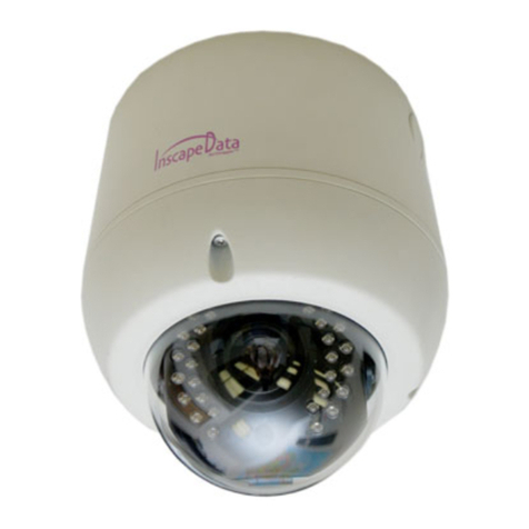
Inscape Data PES100 User manual
Inscape Data
Inscape Data AirGoggle NVC360 User manual
Inscape Data
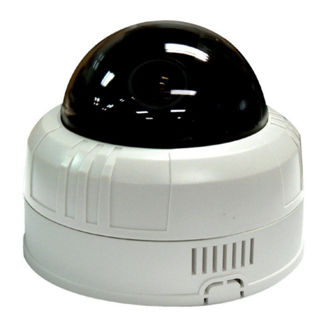
Inscape Data AirGoggle NVC210 User manual
Inscape Data
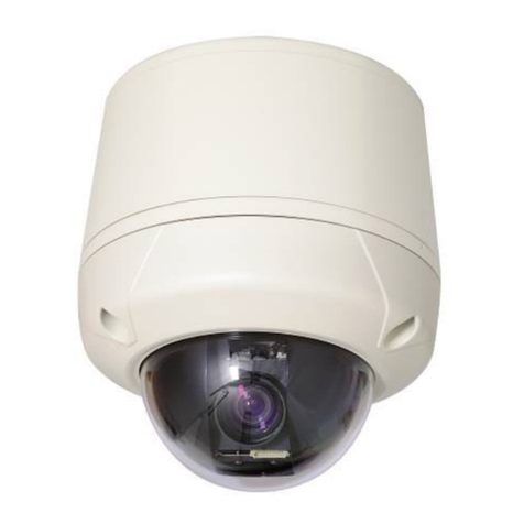
Inscape Data MPEG4 User manual
Inscape Data
Inscape Data AirGoggle NVC 910 User manual

Inscape Data
Inscape Data AirGoggle NVC210 User manual
Inscape Data
Inscape Data NVC 1000 Series User manual
Inscape Data
Inscape Data AirGoggle NVC100 User manual
