Inscape Data AirGoggle NVC360 User manual

Quick Install Guide
AirGoggle™IP Video Camera
QUICK INSTALL GUIDE Rev 0.2 April 2009
Corporate Headquarters
Inscape Data Corporation
1611 South Main Street
Milpitas, CA 95035
USA
http://www.inscapedata.com
Tel: 408 935-8500
1-888-267-4507
Fax: 408 935-8900

Q
QU
UI
IC
CK
K
R
RE
EF
FE
ER
RE
EN
NC
CE
E
G
GU
UI
ID
DE
E
2
1
1.
.
O
Ov
ve
er
rv
vi
ie
ew
w
1
1.
.1
1
B
Bo
ox
x
C
Co
on
nt
te
en
nt
t
Please check to make sure the following items are in the box.
Components Description Remarks
AirGoggle NVC360 AirGoggle NVC360 Network Camera
Power adapter Input : 100~250V 50-60Hz
Output : 12VDC / 3.33A Standard Power
AC power cable AC 250V, 10A~16A
Video cable Cable for analog video output from
camera module inside of network camera
CD-ROM Software, User’s Guide, Quick Installation
Guide
1
1.
.2
2.
.
P
Pr
re
ev
vi
ie
ew
w
NVC360 IP-Installer Viewer Program NVR100
1CH MPEG-4 Network
Camera
PC software to allocate an IP
address to the
AirGoggle_NVC360
PC software to view and record
the A/V streaming data
transmitted from
AirGoggle_NVC360

Q
QU
UI
IC
CK
K
R
RE
EF
FE
ER
RE
EN
NC
CE
E
G
GU
UI
ID
DE
E
3
1
1.
.3
3.
.
P
Ph
hy
ys
si
ic
ca
al
l
d
de
es
sc
cr
ri
ip
pt
ti
io
on
n
1
1.
.3
3.
.1
1.
.
E
Ex
xt
te
er
rn
na
al
l
a
an
nd
d
I
In
nn
ne
er
r
V
Vi
ie
ew
ws
s
Figure 2-1. External and inner views of NVC360
1. Surface mount adaptor
2. Cap screw (PT3/4, 1EA)
3. Main body
4. Focus handle
5. Zoom handle
6. Tilt rotation
7. Horizontal rotation
8. Pan rotation
○
1
○
2
○
3
○
5
○
4
○
6
○
7
○
8
I/O View with RJ45 Network Port,
Power Port, Sensor, and Relay Port

Q
QU
UI
IC
CK
K
R
RE
EF
FE
ER
RE
EN
NC
CE
E
G
GU
UI
ID
DE
E
4
1.3.2. Dip Switch Setting
–
––
A. DIP SWITCH SETTING
-. FLK : Flickerless ON/OFF
-. BLK : BLC ON/OFF
-. LED/H : IR LED Illumination High power
VIDEO
DC LEVEL
SENSITIVITY
DIP SWITCH
FLK
BLK
LED/H

Q
QU
UI
IC
CK
K
R
RE
EF
FE
ER
RE
EN
NC
CE
E
G
GU
UI
ID
DE
E
5
1.3.3. Preparations for the installation
Ceiling Mount Type
1. Fix the surface mount adaptor with 4pcs of screws on the place where you want to install. (FIG. 5)
When you use pipe, please note the standard size of pipe. (FIG.6)
2. Fix the main body on the surface mount adapter by screws. (FIG.7)
3. Push and open gimbals and adjust desired focus and scene by turning and moving the 3-axis bracket by
hand. (FIG.7)
4. Assemble the dome cover by L-Wrench. (FIG.7)
1.3.4. Wall Mount Optional- See User Manual
FIG. 5
46
83.5
FIG. 7
FIG. 6
PT 3/4
12
5
Surface mount
adaptor
Main body
Dome cover
Push & open

Q
QU
UI
IC
CK
K
R
RE
EF
FE
ER
RE
EN
NC
CE
E
G
GU
UI
ID
DE
E
6
2
2.
.
I
In
ns
st
ta
al
ll
la
at
ti
io
on
n
a
an
nd
d
I
IP
P
a
al
ll
lo
oc
ca
at
ti
io
on
n
The setup in this guide utilizes a crossover cable connection between the NVC units and
installation computer as shown in figure 2-1 for easy installation and demonstration of basic
feature sets. The NVC supports network configurations including LAN, ADSL modem, and cable
modems including IP sharing devices. Use normal Ethernet cables in most cases unless
connecting directly between the installation PC and the NVC.
2
2.
.1
1.
.
Q
Qu
ui
ic
ck
k
I
In
ns
st
ta
al
ll
la
at
ti
io
on
n
O
Or
rd
de
er
r
In order to check the functionality of the product, please follow the 3 steps below:
① Connect the installation computer and the NVC product via a crossover Ethernet cable.
② Install the IP-Installer program on the installation computer.
③ Assign an IP address to the NVC product with the IP-Installer.
2
2.
.2
2.
.
C
Co
on
nn
ne
ec
ct
ti
in
ng
g
P
PC
C
a
an
nd
d
t
th
he
e
P
Pr
ro
od
du
uc
ct
t
Figure 2-1 Connecting NVC and PC by cross type LAN Cable
①Apply power to the installation PC and start Windows Operating System.
For further information on LAN, xDSL, and cable modem connections, please refer to
the user manual in the CD provided with the product.
Client PC Crossover LAN Cable

Q
QU
UI
IC
CK
K
R
RE
EF
FE
ER
RE
EN
NC
CE
E
G
GU
UI
ID
DE
E
7
②Apply power to the NVC product and connect it to the installation PC with the crossover LAN
cable as shown in Figure 2-1.
2
2.
.3
3.
.
I
In
ns
st
ta
al
ll
li
in
ng
g
a
an
nd
d
R
Ru
un
nn
ni
in
ng
g
I
IP
P-
-I
In
ns
st
ta
al
ll
le
er
r
P
Pr
ro
og
gr
ra
am
m
2
2.
.3
3.
.1
1
I
In
ns
st
ta
al
ll
li
in
ng
g
I
IP
P-
-I
In
ns
st
ta
al
ll
le
er
r
P
Pr
ro
og
gr
ra
am
m
Insert the product CD provided into the CD-ROM drive of the installation PC and select “2.IP-
installer Software\IPInstaller_V2_1_3_English\install.bat”; the IP-Installer program will be
automatically installed.
2
2.
.3
3.
.2
2
R
Ru
un
nn
ni
in
ng
g
I
IP
P-
-I
In
ns
st
ta
al
ll
le
er
r
P
Pr
ro
og
gr
ra
am
m
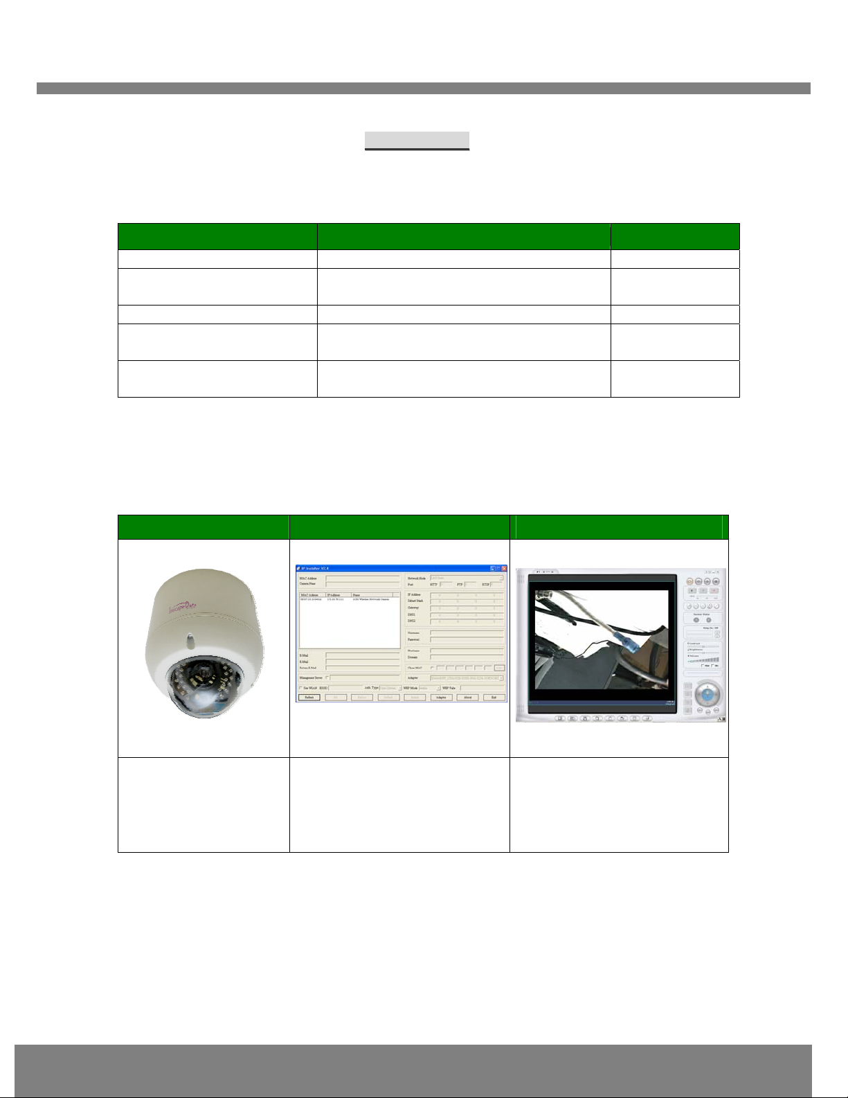
Fig2-2Initial modeofIP-Installer
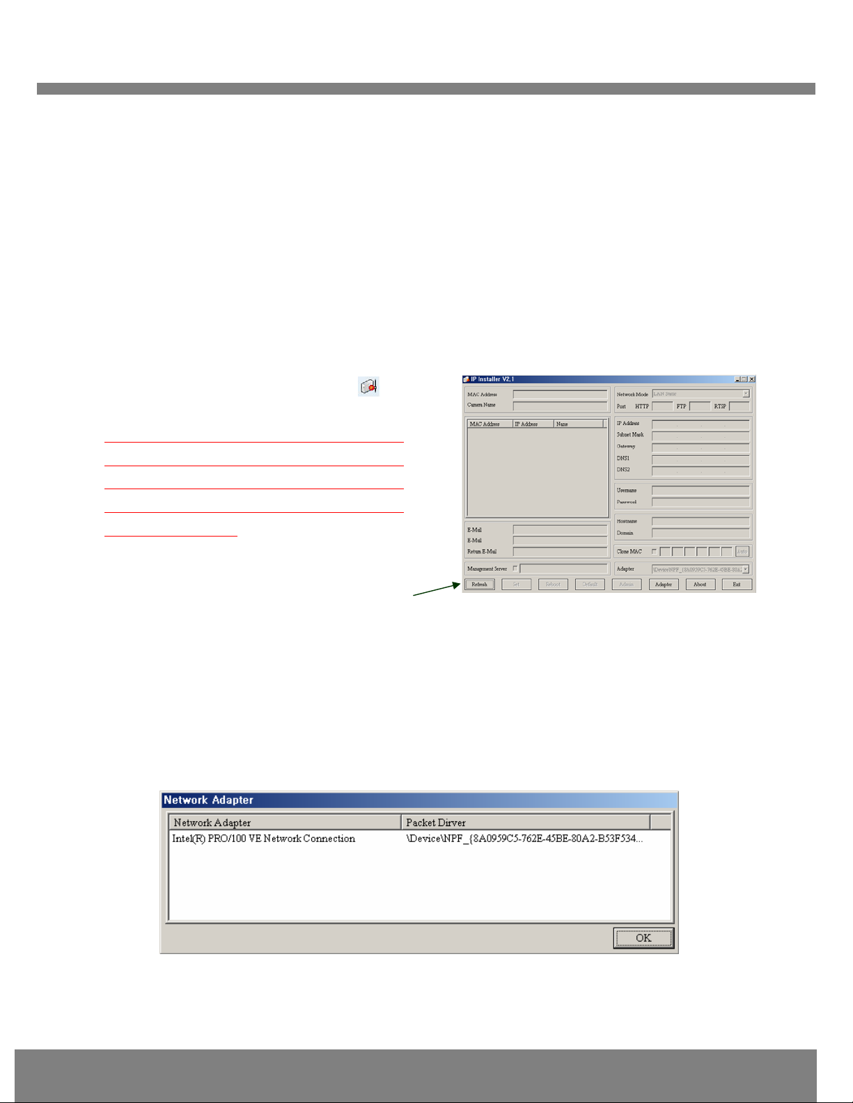
②Network Adapter Selection on Window 2000 or XP
If using Windows 2000 or XP, the PC will ask you to select the proper network adaptor as in
Figure 2-3. It is important to select the right packet driver for the network adaptor. If the PC is
configured to support more than one network (e.g., various MODEM, IEEE1394, etc), the PC
can crash if one selects the wrong packet driver. Click on a network adaptor to highlight, and
then press OK. Figure 2-3 shows an Intel “PRO/100 VE” Ethernet adaptor.
Fig 2-3. Network Adapter Screen Mode
③Click “Refresh” as in Fig 2-4 and check whether the MAC address that appears on the screen
①Double-click the IP-Installer icon ( ) to
start the IP-Installer.
If using Window98SE, press “Refresh”
button
after starting the IP Installer. The attached
camera or server will appear in the left
window of the IP-Installer program. As
shown in figure 2-2.
Refresh Button

Q
QU
UI
IC
CK
K
R
RE
EF
FE
ER
RE
EN
NC
CE
E
G
GU
UI
ID
DE
E
8
matches the one at the bottom of the physical unit. In cases where they do not match, please
contact your authorized sales agent.
④Double-click the MAC address on IP-Installer. Default network setup parameters are
displayed on the right side of the screen as shown in Fig 2-5.
2
2.
.4
4
S
Se
et
tt
ti
in
ng
g
I
IP
P
A
Ad
dd
dr
re
es
ss
s
According to the combinations of network type and IP allocation methods, “Network Mode” can be
“LAN Automatic”, “ADSL Static”, “ADSL Automatic”, “Cable Modem Static”, “Cable Modem
Automatic”, which you can choose from. Settings can vary depending on this “Network Mode”.
This “Quick Installation Guide” will explain only about “LAN Static” mode in which the PC and the
product is directly connected by cross type LAN cable.
Please refer to the user manuals in the CD in the box for detail information
on network modes besides “LAN Static”.
Refresh button MAC Address
Fig 2-4 IP Installer’s Initial Mode
Fig 2-5 Mode after double-click of MAC Address

Q
QU
UI
IC
CK
K
R
RE
EF
FE
ER
RE
EN
NC
CE
E
G
GU
UI
ID
DE
E
9
L
LA
AN
N
S
St
ta
at
ti
ic
c
2
2.
.4
4.
.1
1
.
.
C
Co
om
mp
pl
le
et
ti
in
ng
g
I
IP
P
A
Ad
dd
dr
re
es
ss
s
S
Se
et
tt
ti
in
ng
g
After setting up all the parameters, click on the “Set” button. You will see the following message:
“All values will be saved, and your server will be restarted. Continue?”
Click “Yes” button to save all the values. The unit will be rebooted.
3
3.
.
A
Ac
cc
ce
es
ss
si
in
ng
g
t
to
o
t
th
he
e
P
Pr
ro
od
du
uc
ct
t
a
an
nd
d
C
Ch
he
ec
ck
ki
in
ng
g
B
Ba
as
si
ic
c
F
Fu
un
nc
ct
ti
io
on
n(
(V
Vi
ie
ew
wi
in
ng
g)
)
When IP setting is done with IP-Installer, you must check whether the video stream is
transmitted from the unit. There are two ways to check the video transmission from the unit.
① Using NVR100, the stand-alone software for multi-channel viewing and recording
② Using the conventional web browser (Internet Explorer)
3
3.
.1
1
A
Ac
cc
ce
es
ss
si
in
ng
g
b
by
y
N
NV
VR
R1
10
00
0
P
Pr
ro
og
gr
ra
am
m
3
3.
.1
1.
.1
1
I
In
ns
st
ta
al
ll
li
in
ng
g
N
NV
VR
R1
10
00
0
a
an
nd
d
R
Ru
un
nn
ni
in
ng
g
i
it
t
Insert the installation CD provided with the unit into the CD-ROM drive of the PC and select
“NVR100.exe” from the “NVR100 Software” directory, the NVR100 program will run automatically.
Fixed IP is required in “LAN Static” mode. Select
“LAN Static” and insert “IP address” and “subnet
mask” as shown in Fig 2-6.
Subnet values of both the install PC and the product
must be consistent and only the last portion of IP
addresses of them should be different. (E.g. PC:
211.52.88.210, Product: 211.52. 88.200)
Fig 2-6 Network Setting for LAN Static

Q
QU
UI
IC
CK
K
R
RE
EF
FE
ER
RE
EN
NC
CE
E
G
GU
UI
ID
DE
E
10
3
3.
.1
1.
.2
2
R
Ru
un
nn
ni
in
ng
g
N
NV
VR
R1
10
00
0
P
Pr
ro
og
gr
ra
am
m
Fig 3-1 NVR100 Initial Mode
③Click the “Camera Assignment” button at the bottom, the second from the left. The
IP setting mode screen will appear as shown in Fig 3-2. “Camera Assignment” can be
selected also by clicking the right button of the mouse. As in Fig 3-2, insert the IP
address, channel, user IP (default: root) and password (default: dw2001) and click
at the bottom of the window, then the values set will be saved. (Please make sure that
“Store Pwd” is checked before clicking . Otherwise, the values will not be saved.)
Fig 3-2 NVR100 IP Address Setting Mode
④Click the start button, , and the live video connected to the unit will be transmitted and
appear on your pc screen as shown in Fig 3-3.
① Start the software by double-clicking
the
icon, , on your windows desktop. The
NVR100 software is shown in Fig 3-1.
②The NVR100 is designed to display 16
channels simultaneously. The user can
customize the display mode accordingly to fit
their needs. (Refer to NVR100 user’s Guide for
more detail.)
Camera assignment Button

Q
QU
UI
IC
CK
K
R
RE
EF
FE
ER
RE
EN
NC
CE
E
G
GU
UI
ID
DE
E
11
Fig 3-3 Showing Live Images via NVR100
3
3.
.2
2
A
Ac
cc
ce
es
ss
si
in
ng
g
b
by
y
B
Br
ro
ow
ws
se
er
r
The NVC is designed to be accessed via your favorite web browser in addition to the NVR100
software. In order to access the unit, you must type in the appropriate IP address in the browser.
Fig 3-4 is an example of the web interface.
Fig 3-4 Viewing the Live Video via Web Viewer
P
Pl
le
ea
as
se
e
r
re
ef
fe
er
r
t
to
o
t
th
he
e
N
NV
VR
R1
10
00
0
u
us
se
er
r
m
ma
an
nu
ua
al
l
f
fo
or
r
m
mo
or
re
e
i
in
nf
fo
or
rm
ma
at
ti
io
on
n.
.
Table of contents
Other Inscape Data Security Camera manuals

Inscape Data
Inscape Data AirGoggle NVC210 User manual

Inscape Data
Inscape Data NVC 1000 Series User manual

Inscape Data
Inscape Data AirGoggle NVC 910 User manual

Inscape Data
Inscape Data AirGoggle NVC210 User manual

Inscape Data
Inscape Data AirGoggle NVC100 User manual

Inscape Data
Inscape Data MPEG4 User manual

Inscape Data
Inscape Data PES100 User manual

Inscape Data
Inscape Data AirGoggle NVC800 User manual