INSIGHT IS-DM220/IR/HB User manual

IS-DM220/IR/HB
IS-DM220
Installation
Guide
Indoor/Outdoor
Ver. 1.2
00P6NX223ZXSEA2

2
Table of Contents
1. Indoor Camera
Installation..................................................................................................... 3
1.1 Hard
Ceiling...................................................................................................................
3
1.2 In-Ceiling (T-Bar)
Mounting
.........................................................................................
13
1.3 4S Mount Electrical Box
..............................................................................................
22
1.4 Corner
Mounting..........................................................................................................
25
2. Outdoor Camera
Installation................................................................................................ 29
2.1 Standard/CompactPendant
Mounting........................................................................
29
3. Cable Gland
Installation
....................................................................................................... 34

3
1. Indoor Camera
Installation
1.1 Hard Ceiling
The Fixed Dome IS-DM220 can be installed directly on a wall or ceiling. Please
note that the wall or ceiling must have enough strength to support the IP Dome
Camera.
Items Needed:
z
Vandal Proof/Lightweight Fixed Dome IS-DM220
z
Ethernet Cable
z
DC Jack Cable (supplied; only necessary if not using PoE)
z
Self-tapping Screws (supplied)
z
Rubber Washers (supplied)
z
Plastic Screw Anchors (supplied)
Tools Needed:
z
Tool for drilling
z
(+,–) Screw Drive

4
Follow the steps below to install the IP Dome Camera:
Step 1:
Unpack the IS-DM220/IR/HB IS-DM220 package and take out the IP Dome
Camera.
Step 2:
Release the 2 captive Security Screws with
the supplied Security Torx and open the
Dome Cover.
Figure-1:
Captive Security Screw

5
Step 3:
Press both sides of the Inner Cover and
remove it from the Camera Module.
Step 4:
Unscrew the Module-fastened Screw, as
indicated in the figure, with the screw
driver.

6
Step 5:
Press the sides of the Snap-on Camera
Module, as indicated in the figure, and
detach it from the Dome Camera’s
Housing/ Plate.
Step 6:
Mark the positions of the four screw holes on the base of the Dome Camera at
the chosen installation location.
Vandal Proof IP Dome Camera
Type 1 Type 2
Lightweight Fixed Dome IS-DM220

7
Step 7:
In the marked locations, drill each hole slightly smaller than the supplied
Screw Anchors.
Step 8:
Put supplied Anchors into these drilled holes.
Step 9:
Fasten the Dome Camera’s Housing/
Plate with the four supplied Self-tapping
Screws.
NOTE: Be sure to fix the Self-
tapping Screws with the Rubber
Washers.
Step 10:
Thread the cables (Power/ Ethernet/
Audio/ Alarm) through either the side
conduit entry or back conduit entry, as
illustrated. Users may use a coin to
screw off the conduit entry block for
Vandal Proof IP Dome Camera.
NOTE: The Power Cable is
omitted if using PoE.

8
Connect the Cable(s) to the Unit
Connect the ports (on the Camera
Module) with their cables/wires
respectively, as shown in the figures.
Step 11:
Attach the Snap-on Camera Module
into/ on the Dome Camera Housing/
Plate, and screw the Module-fastened
Screw tightly with the screw driver to
secure the Camera Module.
NOTE: The terminal blocks
should face the side conduit
entry for Vandal Proof IP Dome
Camera, as shown in the figure.
Vandal Proof
Lightweight

9
Step 12:
Connect the power and network outputs.
NOTE: The Power Cable is omitted if using PoE.
STEP 13:
Access the Camera Browser-viewer for viewing images. Please refer to
User’s Manual for further details. Users can also use the Camera’s BNC
Connector for video output while choosing BNC as one streaming in
advance.
Step 14:
Adjust the Camera's zoom level and
focal length via Zoom and Focus Ring
Screws.
NOTE: The zoom level and focal
length might be different with the
Dome Cover on, in this case,
adjusting zoom level and focal
length through the Dome Cover
is recommended.

10
Adjust the Zoom Ring Screw to set the
desired zoom; subsequently, modifying
the Focus Ring Screw to set the desired
focal length.
Step 15:
Adjust the Camera’s Pan/Tilt holder to a desired angle, as shown below. Pan
adjustment range is nearly 360°; rotation angle range approaches to 270°.
Tilt is adjustable between ﹣10° ~ 90°.
Pan Adjustment Tilt Adjustment
NOTE: Adjust the Lens carefully within the limits mentioned above, or
the cables underneath would be harmed.

11
STEP 16:
Put the Inner Cover back to the Camera
Module.
STEP 17:
Replace the Dome Cover back.
For Vandal Proof IP Dome Camera,
please align the arrow mark on the
Dome Cover with the one on the
Housing as shown in the top figure.
For Lightweight Fixed Dome IS-DM220,
please align the arc area on the Dome
Cover with the back conduit entry as
shown in the bottom figure.
Vandal Proof
Lightweight

12
STEP
18:
Screw on the two Torx Screws on
the
side of the Dome Cover tightly to
fasten
the Dome Cover. Camera installation
is
complete.

13
1.2 In-Ceiling (T-Bar) Mounting
The indoor Dome Camera can be mounted with the optional accessory:
In-Ceiling (T-Bar) Mount. The items and tools needed for in-ceiling installation
are listed as follows.
In-Ceiling Mount Package Contents:
In-Ceiling Mount Trim Ring Ceiling Sticker
In-Ceiling Mount Dimension:
Tools Needed:
z
Tool for drilling
z
Phillips Screw Driver
z
Security Torx provided

14
Follow the steps below to install the In-Ceiling (T-Bar) Mounting:
Step 1:
Release the 2 captive Security Screws
with the supplied Security Torx and open
the Dome Cover.
Figure-1:
Captive Security Screw

15
Step 2:
Press both sides of the Plastic Inner
Cover and remove it from the Camera
Module.
Unscrew the Module-fastened Screw, as
indicated in the figure, with the screw
driver.

16
Step 3:
Press the sides of the Snap-on
Camera Module and detach it from the
Dome Camera’s Housing/ Plate.
Note: Users may use a coin
to screw off the conduit entry
block for Vandal Proof IP
Dome Cameral.

17
Step 4:
Attach the Camera Housing/ Plate’s
base to the In-Ceiling Mount’s top
plate, aligning the camera’s rear cable
entry with the entry hole on the
In-Ceiling Mount’s top plate.
Align the three Captive Screws with
the mating screw holes on the Camera
Housing/ Plate’s base. Then tighten
the three Captive Screws as shown in
the figure.
Step 5:
Position the supplied adhesive-backed
Ceiling Sticker (Diameter: 176 mm)
onto the ceiling where the Camera will
be mounted, and cut the ceiling hole
using the template as a guide.

18
Step 6:
Insert the Dome Camera with the
attached In-Ceiling Mount into the
opening and run the Ethernet cable
through the desired cable entry.
Step 7:
Secure the Unit to the ceiling:
Note: Do Not over-tighten the
three fixing screws. If using a
power tool the slip clutch
should be set to the lightest
setting or the clamps could be
damaged.
The In-Ceiling Mount’s Wing Clamps
will draw the Dome Camera Housing/
Plate to the ceiling board until it is
completely flush with the board.

19
Figure-1:
Bottom View of installed In-Ceiling
Mount.
Step 8:
Attach the Snap-on Camera Module to
the Dome Camera Housing/ Plate.
For Vandal Proof IP Dome Camera,
please install the Camera Module with
the terminal blocks facing the side
cable entry.
Step 9:
Tighten the Module-fastening Screw.

20
Step 10:
Connect the Ethernet cable to the
camera’s network connector.
Refer to the Camera Quick Guide for
details regarding the Camera
Connector Definition.
Step 11:
Access the Camera Browser-viewer for viewing images. Please refer to
Chapter Accessing Camera in IS-DM220 User’s Manual for further details.
Users can also use the Camera’s BNC Connector for video output.
Step 12:
Adjust the Zoom Ring Screw to set
the desired zoom; subsequently,
modifying the Focus Ring Screw to
set the desired focal length.
Step 13:
Adjust the Camera to a desired angle by adjusting Pan/Tilt/Rotation. Pan
adjustment range is nearly 360°; rotation angle range approaches to 270°.
Tilt is adjustable between ﹣10° ~ 90°.
NOTE: Adjust the Lens carefully within the limits mentioned above,
or the cables underneath would be harmed.
Step 14:
Reinstall the Plastic Inner Cover.
This manual suits for next models
1
Table of contents
Popular Security Camera manuals by other brands
Onvif
Onvif CM260IR-IP user manual
Avigilon
Avigilon H4 installation guide
Dalsa
Dalsa P-2 Series user manual
Marmitek
Marmitek IP EYE ANYWHERE - QUICK Quick installation guide
EverFocus
EverFocus POLESTAR EHN7260 Quick installation guide
Chesapeake & Midlantic
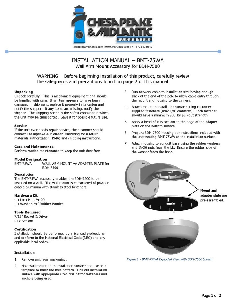
Chesapeake & Midlantic BMT-75WA installation manual
