Insightec Exablate 4000 User manual

PUB41005213 Rev 1.0
Exablate 4000
Checklists Handbook
For Type 1.1 Systems
SW version 7.33 Running on GE MRIs
WARNING:
This document constitutes a shortened reference manual. It does not
replace the Operator Manual. Adhere to all warnings and precautions as
detailed in the Exablate 4000 type 1.0 & 1.1 SW 7. 33 Operator Manual
For Technical Support contact INSIGHTEC at +1-866-674-3874 (US Number)

PUB41005213 Rev 1.0
Copyright ©2021 InSightec Ltd. (“INSIGHTEC”), all rights reserved.
Exablate Model 4000, Type 1.1 Transcranial MR guided focused ultrasound system (“Exablate Neuro”, Software
Version 7.33), processing software, and its related documentation are the confidential proprietary property of
INSIGHTEC. Only licensees of INSIGHTEC (“INSIGHTEC”) have the right to use the information contained herein. Only
licensees specifically granted copy and/or transfer rights have the right to copy and/or transfer this information. Any
unauthorized use, disclosure, assignment, transfer or reproduction of this confidential information will be prosecuted
to the full extent of the law.
INSIGHTEC shall not be liable nor obliged in any manner in respect to any bodily injury and/or property damage arising
from the use of this software if such use is not in strict compliance with the instructions and safety precautions
contained in the relevant operating manuals, including all supplements thereto, in all product labels and according to
the terms of warranty and sale of this software, nor if any changes unauthorized by INSIGHTEC are made to the
software contained herein.
User-provided programs or protocols are not validated nor warranted by INSIGHTEC. The use of data obtained with
such user provided software or protocols are the sole responsibility of the user.
Users should be aware of the risk of transmission of computer viruses by exchanging files and CDs.
Trademarks of third-party proprietors are the sole property of those proprietors.
Specifications are subject to change without notice and following applicable regulation and laws.
One or more parts of the product may incorporate or be distributed with open source software. Refer to the Copyright
Notice button in the Utilities Screen.
This document is the property of INSIGHTEC Ltd, and contains proprietary and confidential information of INSIGHTEC
Ltd. A nondisclosure agreement between the recipient and INSIGHTEC Ltd. has been executed prior to receipt of this
document. This document is loaned on the express conditions that ne it nor the information contained the
information contained therein shall be disclosed to others without the express consent of INSIGHTEC Ltd. In addition,
the document shall be returned to INSIGHTEC Ltd. upon request with no copies made.
For Technical Support contact INSIGHTEC at +1-866-674-3874 (US Number)
INSIGHTEC website: http://www.insightec.com/
REVISION INFORMATION
This is the Revision 1 release of the Exablate 4000 Type 1.1 Handbook for SW version 7.33, applicable GE MR
systems. Please contact Insightec Marketing Support to determine if this is the most current release.
Each chapter of this manual has a chapter revision level and date at the bottom. This indicates the release level &
date for the individual chapters. Note that when the manual is updated, not all of the chapters are necessarily
updated, so some chapters may have a revision level earlier than the release revision level.
The cover page and this page are all Revision 1.0 with the corresponding chapters of the manual:
Chapter #
Chapter Name
Chapter Revision,
Date
# of Pages
in Chapter
Chapter 1
System Setup Checklist
1.0, 04/21
2
Chapter 2
Preparation and DQA Checklist
1.0, 04/21
2
Chapter 3
Treatment Checklist
1.0, 04/21
2
Chapter 4
Cleaning Procedure Checklist
1.0, 04/21
2
Chapter 5
TG Calibration Checklist
1.0, 04/21
2*
* - Including blank back pages

PUB41005213 Rev 1.0 Exablate 4000 Type 1.1 SW v7.33 –Checklists Handbook (GE)
TG-CALIB.
CLEAN
TREAT
PREPARE
SET - UP
1
System Set Up Checklist
NOTE:
The water system will reach its optimal operating conditions within 30 minutes. Take
this into consideration and turn on the system as early as possible before the
treatment, to avoid downtime when the patient arrives.
NOTE:
Multiple flows exist for System setup, consult the flowcharts on the bottom of this
Checklist and select the option most suitable to your workflow and preferences.
If turning on the System prior to connecting the Helmet System cables to the Front
End Unit, press the Operator Stop Sonication Button to re-initialize connections.
Confirm that the MR console was rebooted at the beginning of the day. If not, reboot it.
Connecting the Helmet System Cables to the Front End Unit
Unlock the Storage and Transfer Cart (STC) wheels, and position it near the Front End Unit (FE)
Connect the Water Cable and the two, uniquely labeled, Quick Coupler Cables to the Front End
CAUTION:
Verify that each Quick Coupler connector is connected to its intended labeled
position. The connectors must be gently aligned into place before locking.
Ensure that the water cable is fully coupled, as indicated by a ‘Click’ sound.
System Power On
Turn on the System by pressing the green Power On switch located on the operator’s console.
The Begin Logon notice will appear.
Remove all external media drives and/or CD’s from the console computer.
Press ”Ctrl+Alt+Delete” to access the logon information dialog box.
Login with the Username and Password provided to you by Insightec. Click “OK”to continue.
(Note: Windows® login parameters are case sensitive)
Select "Brain Mid-Frequency" from the application selection screen.
The Exablate disclaimer popup window will open; click “OK”to continue.
Preparing the Water System
Unload the Water Reservoir from The Water Reservoir Compartment in the Front End Unit and
disconnect it via the Quick Release Cable.
Fill the Reservoir up to the marking, Connect and return it to its designated compartment
Use fresh Reverse Osmosis water for DQA and cleaning, Type 2 medical grade water for treatments
Set the water system to “Preparation” either from the Workstation “Utilities” menu ( ) or from
the Water System Control Touchscreen
Degassing will start. The status of the Water System and Dissolved Oxygen (DO) levels [in PPM]) are
indicated on the status bar on the bottom of the Workstation screen and the screen in the FE Unit.
NOTE:
You may proceed with System Set Up while water preparation is ongoing, Degassing
will proceed (unless manually halted) until the operator fills the Transducer

PUB41005213 Rev 1.0 Exablate 4000 Type 1.1 SW v7.33 –Checklists Handbook (GE)
TG-CALIB.
CLEAN
TREAT
PREPARE
SET - UP
2
Preparing the MR Table
Bring the MR cradle all the way out of the MRI bore
Remove any imaging coils or MRI Baseplates currently connected to the MRI Table
Place the Exablate MR Baseplate on the MR Table and ensure it is fully coupled
Positioning the Helmet System on the MR Table
Unlock the STC's wheels and roll it towards the MR Table while releasing the cables
Place the STC perpendicularly to the MR Table, so that the markings are aligned
Lock the STC’s wheels in place
Release and lower the Coupling Bridge. Ensure full connection between Coupling bridge and MR table.
CAUTION:
To avoid damage to the system components, ensure there is a clear path between the
Helmet System and its designated position on the MR Adapter Baseplate.
Place your hands on the Auxiliary and Main Handles. While pressing the “Transducer Release Button”,
slowly and firmly slide the Helmet System into place. A ‘Clicking’ sound denotes full coupling.
Lower the Main Lock to secure the Helmet System in place
Connect Tracking and Head coil Connector/s to the MRI Table
Connect the Patient Stop Sonication Button cord to the socket on the MRI Table.
Place and\or align Landmark Labels
Unlock the STC wheels and roll it away from the MR table. it will not be needed until after the treatment
Verify System is Ready for Treatment
Confirm that the System and MR status fields are “Ready” on Workstation screen, and the green System
Power Indicator on the operator console is illuminated.
With GE SW version DV26 and up you may need to press the 'External Host' button on the
MR WS and select 'ExAblate' from the drop down menu in order to enable communications.
WARNING:
Visually inspect the Exablate System to:
●Verify the integrity of the Transducer, Front End and MR Table
●Confirm that the connectors are properly fastened
●Confirm that the Exablate MR Baseplate and Helmet System are properly docked
Failure to follow these instructions may result in improper system function.
System Setup Flow Option Charts
A
CONNECT TO
FRONT END
TURN ON
SYSTEM
PREPARE
WATER
MOUNT HS
ON MR
TABLE
READY
C
TURN ON
SYSTEM
PREPARE
WATER
MOUNT HS
ON MR TABLE
CONNECT TO
FRONT END
CONNECT TO
FRONT END
MOUNT HS
ON MR
TABLE
PRESS AND
RELEASE
PHYSICIAN STOP
SONICATION
BUTTON
READY
MOUNT HS
ON MR
TABLE
CONNECT TO
FRONT END
TURN ON
SYSTEM
PREPARE
WATER
READY
B
PUB41005213 Rev 1.0 Exablate 4000 Type 1.1 SW v7.33 –Checklists Handbook (GE)
SET - UP
TG-CALIB.
CLEAN
TREAT
PREPARE
3
Preparation Checklist
System Set-Up for DQA
Perform one of the System Setup flow options as defined by the System Set Up Checklist
Ensure the Transducer is located in "Home Position", according to label on Positioner
Affix the Patient Membrane intended for the treatment into the DQA Holder Setup
Place a DQA Phantom into DQA Holder Setup, and lock it onto the Helmet System and Transducer
Plug the Head Coil into its dedicated connector (if applicable)
Make sure the transducer’s Air Release Valve is open. Fill transducer with water until slightly convex
Close Air Release Valve. Release excess air from pipes via the Red Excess Air Release button
Perform short mandatory fill to replace lost water. Ensure no leaks. Begin water Circulation
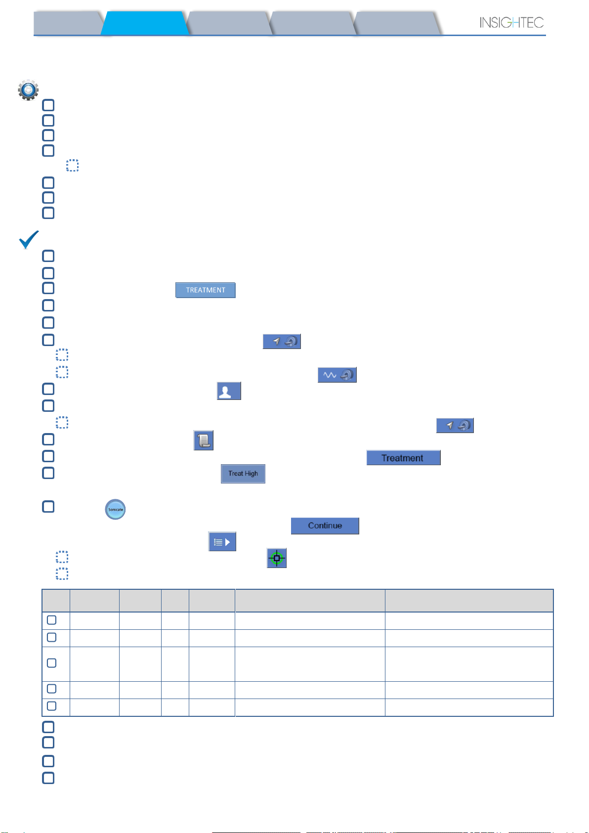
DQA Procedure
On MR scanner console: Register patient
In MR room: Set Landmark and Advance Cradle to scan position
Start a New Treatment from the main menu of the Exablate application software
On MR scanner console: Prescribe and run a 3-Plane Localizer scan
On MR scanner console: Prescribe and run 3 orientations of DQA planning images (Sag, Ax and Cor)
Run Automatic Transducer Tracking scan
On 3T MR: skip TG calibration (select "Cancel")
Perform an MRI central frequency scan (optional)
Open the Image Retrieval Dialog , select and upload the three DQA planning series
Ensure the Transducer Focal Point is located at the center of the DQA phantom
If required: Reposition the transducer & Re-Run a Transducer Tracking scan
Set the Treatment Protocol to Brain-DQA
Press Stop Sonication Button and proceed to Treatment Stage
Set Treatment level to Treat High
NOTE: In the DQA procedure, there is NO need to use CT images or run Movement Detection scans
Sonicate the predefined set of 5 spots using the parameters outlined in the following table
Press Continue to proceed to the next sonication
Use the next sonication button to switch between the predefined spots.
Review results and Adjust Spot Location if it is not in place (>1.5mm from target)
Repeat sonications as needed (after adjust, if images are with artifacts, unclear thermal rise etc.)
Spot #
Orientation
Frequency
Direction
Power
Duration
Goal [Expected Temperature]
Spot Confirmation
1
Axial
AP
20 W
13 Sec
Geometric alignment
Spot is clearly visible, aligned in RL
2
Sagittal
AP
20 W
13 Sec
Geometric alignment
Spot is clearly visible, aligned in SI
3
Axial
RL
30 W
13 Sec
Geometric alignment
Temperature increase
Spot is clearly visible, aligned in AP
4
Axial
RL
30 W
13 Sec
Steering verification
Steered focus to the correct side
5
Axial
RL
250W
3 Sec
Cavitation Control
Confirm Active Power Modulation
Quit the treatment and return to entrance screen, drain water from transducer. Set to Degassing
Unplug and dry the Patient Membrane, and stow the DQA Phantom holder setup away
Set the Transducer as Superiorly as possible. Return DQA Phantom to package, mark number of uses.
Prepare table for patient arrival: mattresses (cover with blankets), cushions, warm blankets, etc.
PUB41005213 Rev 1.0 Exablate 4000 Type 1.1 SW v7.33 –Checklists Handbook (GE)
SET - UP
TG-CALIB.
CLEAN
TREAT
PREPARE
4
Pre-Treatment Preparations
Make sure all necessary INSIGHTEC accessories are available –For one treatment procedure:
Ensure availability of a CT scan (mandatory) and pre-treatment MR (optional)
Prepare Pre-Treatment Plan (with or without pre-treatment MR images)
Perform Daily Quality Assurance (DQA) as outlined in this document
Ensure water system is in active degassing mode, transducer is positioned as superiorly as possible.
Patient Preparation
Confirm patient is shaved and the scalp is cleaned with alcohol.
Ensure IV line is in place
Fit the patient with Compression Stockings [recommended]
Select the appropriate frontal bar (nominal or small) based on the patient's head dimensions
If using the headframe based on INTEGRA UCHRA (Legacy), an optional frontal bar is available
Affix the Head Frame, as inferiorly as possible above the eyebrows
Place the Patient Membrane on the patient’s head, as low as possible, in the right orientation:
Membrane without coil: screw\clasp side down (towards patient's feet)
Membrane with coil: coil connectors towards the patient's feet and neck
Note: If using a single use Membrane it may require cutting to fit the patient
Patient Positioning
Ensure the transducer is placed in the "Home" position (as defined by label on HS)
Bring the patient into the MR suite. Assist patient on Table
Attach Frame to Baseplate and Membrane to Transducer
Plug the Head Coil into its dedicated connector (if applicable)
Fit earplugs and Mirrored Glasses (optional), Cover patient with warming Blankets
Restrain patient’s feet and body with straps and use patient Leg holder if needed
Equip patient with Stop Sonication button
Move Transducer to estimated clinical position. Ensure clearance between patient and Transducer
Fill transducer with water until slightly convex (via Water Control Screen or Remote Controller)
Close Air Release Valve. Release excess air from pipes via the Red Excess Air Release button
Fill additional water to replace lost water. Ensure no leaks. Begin Treatment Circulation
Minimize membrane air folds within transducer’s pass zone
Ensure cables are free to move and advance cradle to scan position
The patient and the Exablate system are now ready for treatment…
INSIGHTEC PATIENT AND TREATMENT ACCESSORIES
DQA Phantom
DQA Holder Setup
Patient Membrane
Assembled Head Frame
Front Bar for Small Heads
Head Frame Positioning Straps
x2 Head Ring Wrench
x4 Disposable Head Frame Screws
x4 Protective Frame Pin Caps
PATIENT MANAGEMENT
Surgical Marker
Razor/shaving tools
Warming Blankets
Ear Plugs
IV Line
Compression Stockings
Blood Pressure/pulse Oxy
Pin Site Anesthesia

PUB41005213 Rev 1.0 Exablate 4000 Type 1.1 SW v7.33 –Checklists Handbook (GE)
PREPARE
SET - UP
TG-CALIB.
CLEAN
TREAT
5
Treatment Checklist –Planning Stage
on MR scanner console: Register Patient, In MR Room: Set Landmark-center according to labels
on MR scanner console: Prescribe and run a 3-Plane Localizer scan
Run Automatic Transducer Tracking scan
On 3T DV26 (or higher) only: choose to perform or skip TG calibration (See TG-CALIB. Checklist)
Perform an MRI central frequency scan
Select an appropriate Treatment Protocol
Load Pre-Plan if available. Otherwise load CT scan (Pre-op MR is optional)
on MR scanner console: Plan the first orientation\volumetric series on the MR Console
Select 2D or Volumetric scan protocols, according to imaging preference
Take care to place your mid-slice along the AC-PC Plane
Up to 150 Axial\Sagittal\Coronal slices (Non-Volumetric)
Scan Prepared Series (Note: The Step last edited will be the one scanned)
Wait for automatic Movement Detection Reference images acquisition to finish
Choose an image acquisition method and proceed accordingly:
Reformat Mode
Locate and place the AC and PC
Define the Mid-Line
(Parallel to anatomical midline)
Turn Reformat Mode ON
Press to create volume
Fine-tune orientations.
press to create series
Scan by AC-PC
Locate and place the AC and PC
Define the Mid-Line
(Parallel to anatomical midline)
Scan remaining orientations
User may perform targeting during scans
Alternative Method: acquire images via scan prepared series or from Archive
If No Movement Detection Images have been acquired, press to acquire
Run Auto-Registration
adjust manually (If necessary) until satisfactory registration is obtained
Determine target by measurements
→
OR by manual input of AC-PC\RAS coordinates
Check distance between transducer focus and target
If necessary, adjust transducer location and re-run Transducer Tracking scan
If not already part of pre-plan, press the Auto-Sinus & calcification Marking tool
Review the CT images to evaluate sinus and calcification markings
If necessary, add markings using the Polygonal and Spherical NPR tools
Use the Interpolate tool to auto-draw Polygons between marked slices
Mark Membrane Folds on Axial MR series with the Polygonal NPR and Interpolate tools
Confirm Water Temperature<19oCand PPM Level<2.0 (displayed on lower left corner of screen)
Instruct Patient to press Stop Sonication Button. proceed to Treatment Stage
PUB41005213 Rev 1.0 Exablate 4000 Type 1.1 SW v7.33 –Checklists Handbook (GE)
PREPARE
SET - UP
TG-CALIB.
CLEAN
TREAT
6
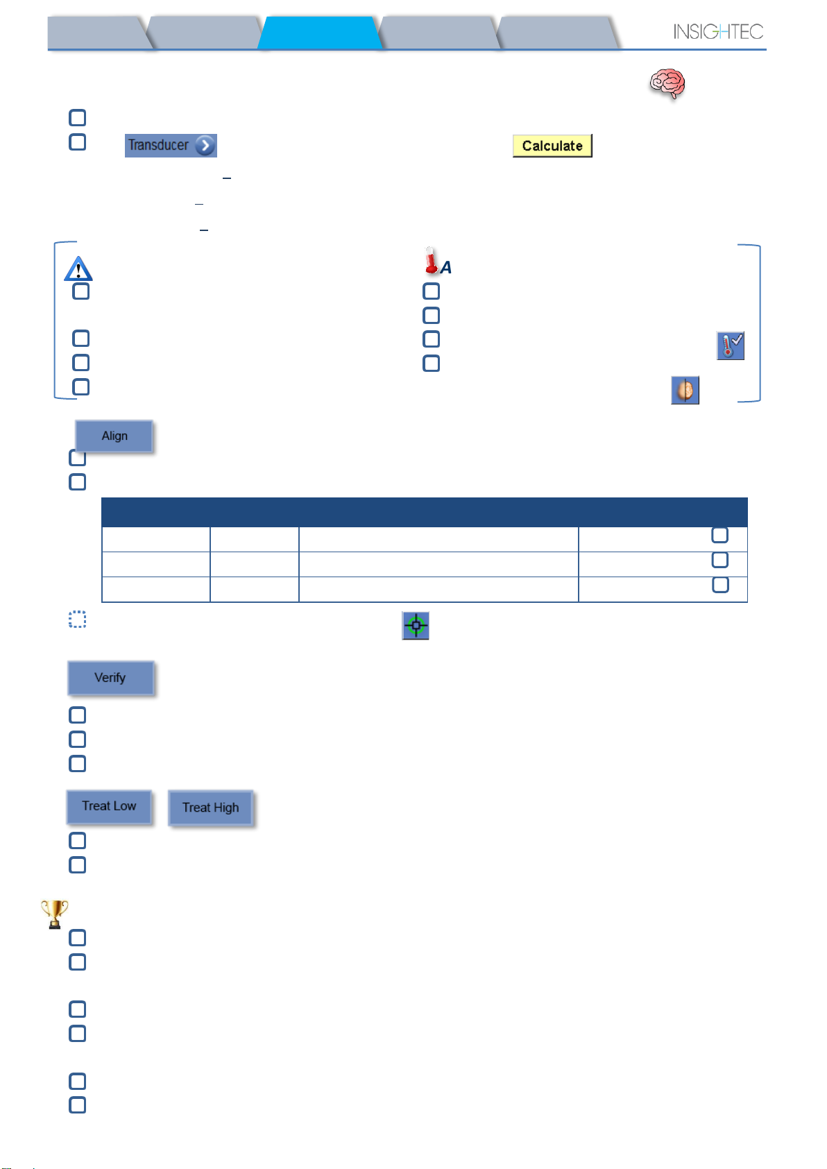
Treatment Checklist –Treatment Stage
Verify spot is on target location and Locked
Press to display Transducer Element Map. Press and confirm:
!# Elements ON > 700
!Skull Area > 200cm2
!Skull Score > 0.4 (or according to regional labeling)
Prior to Applying Sonication
Set Sonication Power, Duration and Time
Extension
Set Scan Orientation, Frequency Direction
Confirm Water Temperature<19oC
Confirm PPM Level<2.0
After Every Sonication
Verify spot alignment
Check for Heating outside of treatment area
Update Peak Temperature if necessary
If Background Temperature is inconsistent,
enable Background Elimination
Sonicate and check location of spot along phase direction, keeping sub-lesional target temp.
Verify alignment for every direction. See table for reference:
Sonications #
Validating
Orientations (frequency directions)
Result
RL
Axial(AP) OR Coronal(SI)
Confirmed R\L
AP
Sagittal(SI) OR Axial(RL)
Confirmed A\P
SI
Coronal(RL) OR Sagittal(AP)
Confirmed S\I
If spot is misaligned, use the Geo-Adjust Tool to pinpoint the center of the spot
!Continue to next level only after spot is clearly visible and aligned along ALL orientations
Proceed to verify stage. Accumulated adjustments [mm]: RL: ______ AP: ______ SI: ______.
Gradually increase energies by 10%-25% until reaching temperature of ~50oC
Evaluate Patient before proceeding to “Treat Low”
Gradually increase energies by 10%-25% until achieving effect & permanent lesioning temperatures
If necessary, adjust Target Location
Post-Treatment Procedures
Open the Air Release Valve on top of the Transducer and Drain the water from the Transducer.
Disconnect Head Coil (if applicable), Release and handle the Membrane as defined at the end of the
Cleaning Procedure Checklist, move transducer as superiorly as possible.
Release Head Frame from the Baseplate, take the patient off the Table and Remove the Head frame.
Transfer Helmet System to the Cart. Perform the cleaning as defined by Cleaning Procedure Checklist,
or further detailed in the Cleaning and Disinfection Chapter of the Operator Manual.
After the Cleaning, drain Transducer, discard drained water, and Shut Down System.
Check availability of DQA Phantom and Patient Membrane for next treatment.
PUB41005213Rev 1.0 Exablate 4000 Type 1.0 SW v7.33 –Checklists Handbook
7
TREAT
PREPARE
SET - UP
B1-CALIB.
CLEAN
Cleaning Procedure Checklist
The Exablate Cleaning Procedure Requires:
•Water Tank Disinfectant - 50 ml Sodium Hypochlorite (CAS # 7681-52-9) 4.00% - 4.99%
•Cleaning & Disinfection Wipes - containing 0.2 - 0.4% of benzalkonium chloride (CAS # 8001-54-5)
Water System Cleaning Procedure
Wipe the patient membrane with dedicated cleaning & Disinfection wipes and allow to dry
Ensure Transducer is empty and all water used during the procedure has been discarded of
Fill the Water System Reservoir (Tank) with ~13 liters of fresh Reverse Osmosis water
Pour Water Tank Disinfectant in the Tank and re-connect it
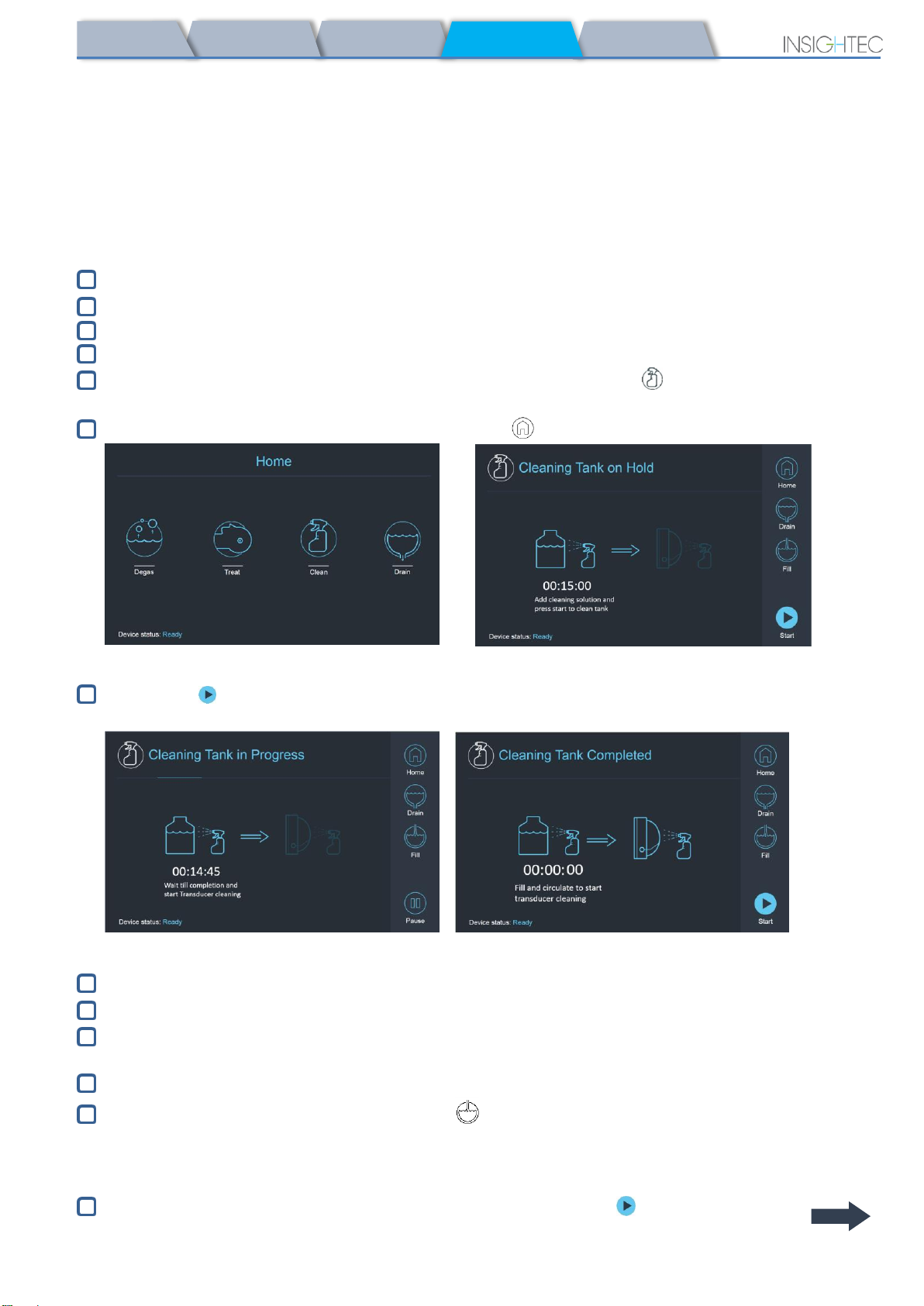
On the Water System home screen (Figure 1A), press the “Clean” option
The system will switch to Clean Mode (Figure 1B)
(Note: If not at home screen, press the “Home” button )
Fig. 1A: Water System Touchscreen “Home” Menu Fig. 2B: Water System “Clean” Menu – on Hold
Press “Start” button to start the cleaning operation (Figure 2A). A countdown timer on the
WS status bar and water system screen displays the remaining cleaning time of the Tank
Fig. 2A: “Tank Cleaning in Progress” Screen Fig. 2B:–“Cleaning Tank Completed” Screen
Mount Patient Membrane on the DQA holder setup (without a DQA phantom)
Attach the DQA holder setup to the HS and seal the Transducer
A “Cleaning Tank Completed” message (Figure 2B) will appear when the timer reaches zero. The system
is now ready for stage two of the cleaning cycle –Transducer cleaning.
Verify that the Transducer is connected to the water system connector at the Front-End
Fill the Transducer by pressing the “Fill” button on the Screen or on the Water System Remote
Controller. Close the Valve once the Transducer is full.
(Tip: bringing the Transducer to an inferior position reduces the required volume for filling the
Transducer interface, shortening fill and drain times for the transducer cleaning procedure)
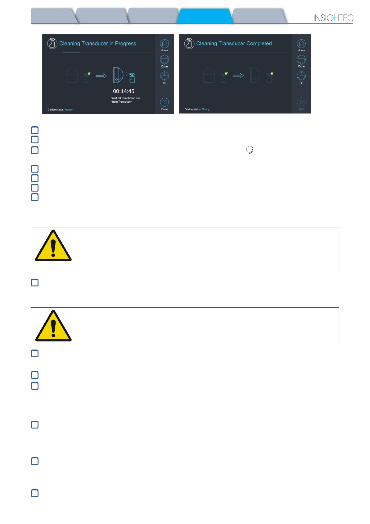
Start the “Cleaning Transducer” timer by pressing the “Start” button on the Screen
(Figure 3A) or on the Water System Remote Controller
PUB41005213Rev 1.0 Exablate 4000 Type 1.0 SW v7.33 –Checklists Handbook
8
TREAT
PREPARE
SET - UP
B1-CALIB.
CLEAN
Fig. 3A: “Cleaning Transducer in Progress” Screen Fig. 3B:“Cleaning Transducer Complete” Screen
When timer is over, the Transducer cleaning is completed (Figure 3B)
Set the Release Valve to air
Drain the water from the Transducer by pressing the “Drain” button on the Screen or on the Water
System Remote Controller
Dispose the water from the Water Tank according to the site and/or local regulations.
Leave the Tank open to air (without the cap)
Replace the phantom holder interface membrane with the protective transducer cover
Turn off the Exablate® Workstation if no more treatments are scheduled for the day
Patient Membrane and DQA Phantom Gel Handling
It is recommended to wear personal protective equipment (i.e. gloves) when handling the accessories.
Multi Use Accessories
WARNING:
Multi-Use Patient Membranes (with/without coil) and DQA Phantom are intended
for limited re-use of up to 5 treatments
Before and after each cleaning cycle , wipe DQA Phantom and the Patient Membrane (inc. coil)
thoroughly with cleaning & disinfection wipes. Pay extra care to the internal edges of the Membrane.
Store the Patient Membrane and DQA Phantom in their original packaging. Mark number of uses.
Discard of membranes, DQA Phantom and their storage box (according to the local/site procedures)
after their fifth use or in case of any visual signs of damage.
Single Use (Legacy) Accessories
Discard of membrane and DQA Phantom Gel and their storage boxes following the conclusion of a
treatment (according to the local/site procedures).
Wiping the Transducer
Before and after each cleaning cycle, clean the internal surface of the Transducer with the cleaning &
disinfection wipes
Do not apply force on the Transducer surface
Following treatment, place the protective cover to cover the Transducer surface
WARNING:
Failing to comply with Patient Membrane and DQA Phantom Gel Handling
instructions may result in reduced imaging quality, water leakage, cross-
contamination, burns, electrocution risk and false/unreliable DQA results
PUB41005213Rev 1.0 Exablate 4000 Type 1.0 SW v7.33 –Checklists Handbook
CLEAN
TREAT
PREPARE
SET - UP
TG-CALIB.
9
TG Calibration Checklist
Note: Applicable Only for 3T GE MR Scanners running DV26 or higher
Perform once per treatment (after 3D localizer) in order to improve image quality.
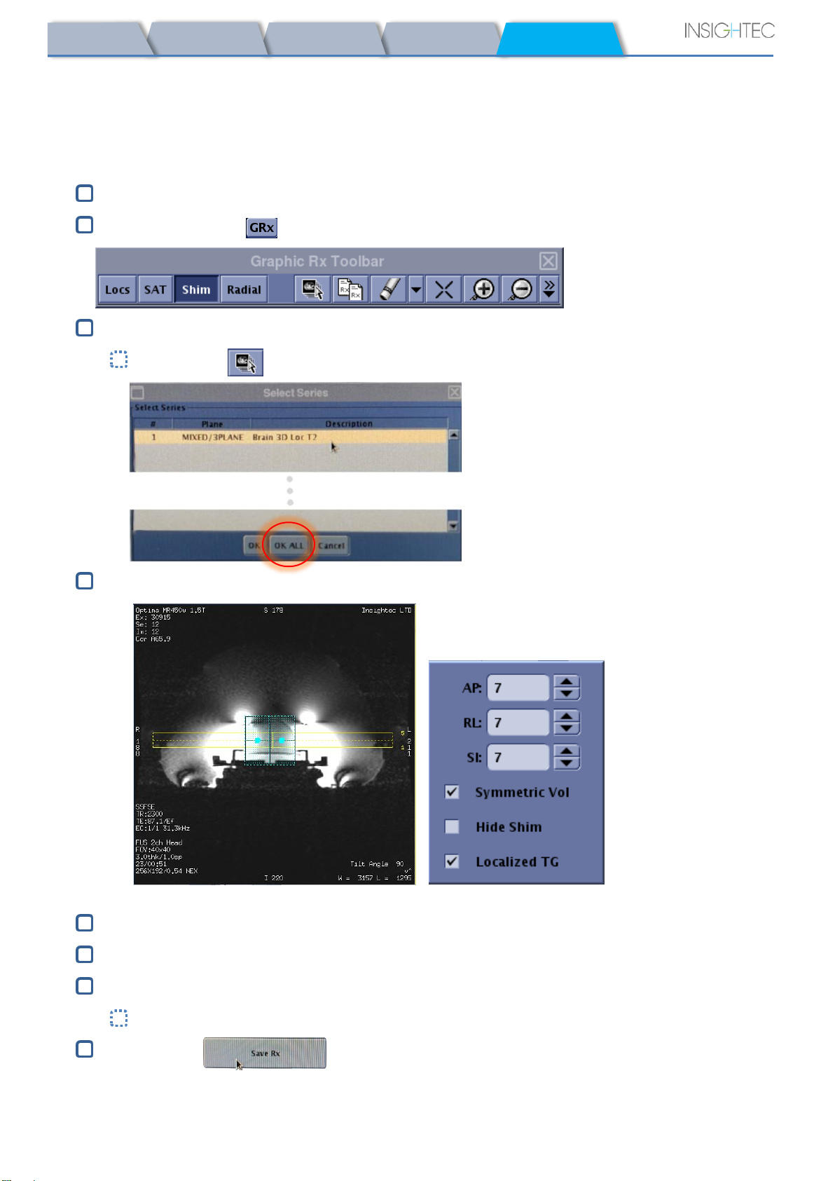
Once scanned, Duplicate & Edit the 3D localizer scan on the MR console screen
Press the GRx button to bring up the Graphic Rx toolbar:
Make sure the 3D localizer is displayed on the MR screen as planning background
If not - Press , select the 3D Localizer series and press "OK ALL"
Press Shim and click on one of the image windows to display the local Shim volume mesh:
Example of local Shim volume (in teal) Shim menu
In the Shim menu, enable Localized TG (mandatory)
Drag the Shim Volume so it is centered roughly around the targeted area
Set the volume size along each direction to 7-9. Ensure full volume is within brain tissue.
Enabling "Symmetric Vol" allows quicker changing of shim volume size
Save the series and proceed with the treatment flow on the FUS Workstation

PUB41005213Rev 1.0 Exablate 4000 Type 1.0 SW v7.33 –Checklists Handbook
10
Table of contents
Other Insightec Medical Equipment manuals

Popular Medical Equipment manuals by other brands

Primedic
Primedic HeartSave AED operating manual

Fresenius Medical Care
Fresenius Medical Care DIASAFE 2008 K Operator's guide

Vitalograph
Vitalograph ALPHA Touch quick start guide

Oxus
Oxus RAK-U06M user manual

Beurer
Beurer IH 58 Kids Instructions for use

Stryker
Stryker Performance-LOAD Cot Fastener System Operation manual


