Insinger OUTPOST Manual

TECHNICAL MANUAL
Installation, Operation and Maintenance Instructions
OUTPOST
(FOOT PEDAL OPERATED)
(FLOOR / WALL MOUNTED)
Insinger Machine Company
6245 State Road
Philadelphia, PA 19135-2996
800-344-4802
Fax: 215-624-6966
www.insingermachine.com
HAND SANITIZING UNIT
P/N: 9700-02327
2
OUTPOST www.insingermachine.com
800-344-4802
INTRODUCTION
Thank you for purchasing a quality Insinger product.
In the space provided below please record the model, serial
number and Installation date of this unit:
Model: OUTPOST
Serial Number:___________________________
Start-Up Date:____________________________
When referring to this equipment please have this information
available.
Each piece of equipment at Insinger is carefully tested before
shipment for proper operation. If the need for service should arise
please contact your local Authorized Insinger Service Company.
To find your local authorized Service Company please visit our
web site, www.insingermachine.com or call Insinger at
800-344-4802.
Please read all installation and operation instructions carefully
before attempting to install or operate your new Insinger product.
For answers to question concerning installation, operation, or
service contact our Technical Service Department.
TECHNICAL SERVICE CONTACTS
Toll-Free
Fax
Email
Website
800-344-4802
215-624-6966
service@insingermachine.com
www.insingermachine.com
WARRANTY
THIS UNIT COMES WITH A 90 DAY
PART DEFECT WARRANTY

3
OUTPOST www.insingermachine.com
800-344-4802
SPECIFICATION SHEET
39.50
31.75
36.50
12.00
10.50
13.50
9.38
REMOVED FOR UNITS
PLACED AGAINST A WALL
4.75
1.75
A
4
OUTPOST www.insingermachine.com
800-344-4802
INSTALLATION
INSTALLATION INSTRUCTIONS
1. Carefully unbox the unit. Take caution not to damage components.
2. Remove any plastic film that may be covering sheel metal parts.
FOR UNITS PLACED AGAINST A WALL:
1. Push unit as close to the wall as possible.
2. If desired, the unit can be secured to a wall by alligning a wall stud
to one of the holes in the back of the unit and then fasten with
apropriate screw.
3. If the unit is greater than 3 inches away from the wall, it is
recommended that the rear foot be installed.
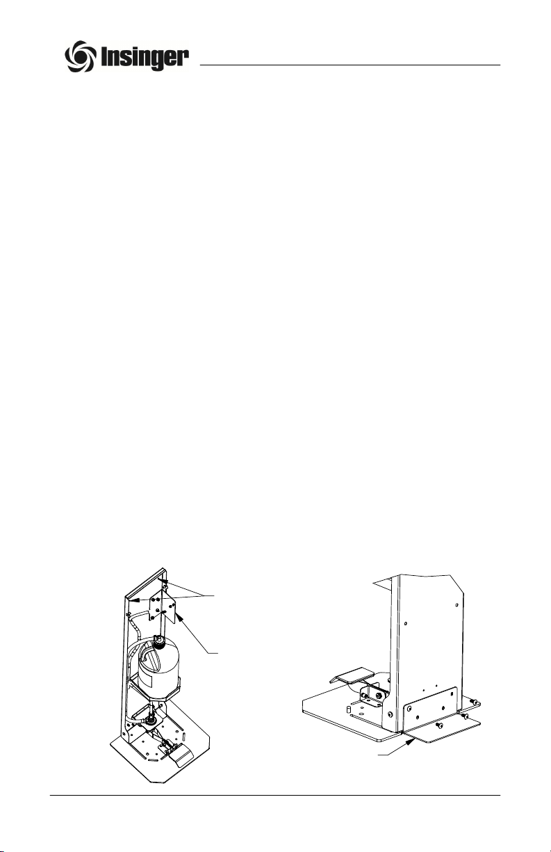
FOR FREE STANDING UNITS:
1. Unlock the units hood and tilt foward.
2. Locate the Rear Foot that is mounted to the upper back of the unit.
Remove the foot and retain the 4 screws and the 4 lockwashers.
3. Install the Rear Foot to the back of the unit as illustrated. The slots
will allow for a certain amount of leveling. Ensure that the base of the
foot is in complete contact with the floor before tightening the
screws.
4. Follow procedures to install a new bottle of sanitizing agent.
REAR FOOT
STORAGE
INSTALLATION
OF REAR FOOT
HOLES FOR WALL
MOUNTING
5
OUTPOST www.insingermachine.com
800-344-4802
INSTALLATION
INSTALLATION INSTRUCTIONS (Continued)
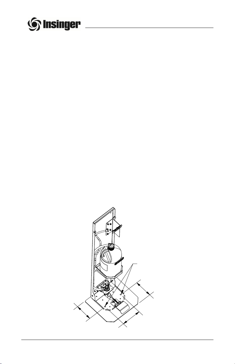
FOR BOLTED DOWN UNITS:
1. Unlock the units hood and tilt foward.
2. Disconnect the discharge hose at the metal tubing in the hood
cavity and remove the dress panel with its attached hood. There
are 2 screws along each side at the back and 2 screws below the
foot pedal for a total of 6 screws.
3. There are two holes in the base that are 6 inches apart that can
be utilized to bolt the base down. Any bolts and / or anchoring
points are entirely the responsibility of the customer.
4. After securing base, Reinstall the Dress Panel with the attached
Hood.
5. Reconnect the Hose to the metal tubing leading to the nozzle.
6. Follow bottle changing procedures to provide sanitizing agent to
the unit.
7. Tilt the Hood back into position and lock the unit.
5
.
4
3
5
.
1
2
6
.
0
0
FLOOR
MOUNTING
HOLES
6
OUTPOST www.insingermachine.com
800-344-4802
OPERATION
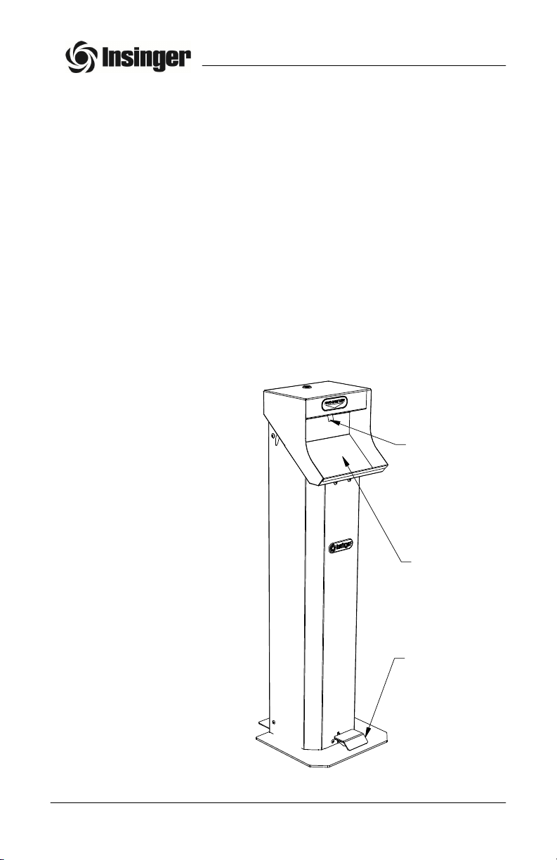
OPERATING INSTRUCTIONS
1. Place hand / hands under the dispensing nozzle located above
the catch tray.
2. Slowly step down upon the foot pedal located at floor level at the
front of the unit.
3. The sanitizing agent will be dispensed onto you hands in a fine
mist for alcohol based sanitizers and in a stream for sanitizing
gels.
4. After the spray stops, release the foot pedal.
5. If additional sanitizing agent is desired, repeat the process.
6. Rub hands together throughly for 30 seconds to ensure that all
areas of your hands are covered.
Dispensing
Nozzle
Catch Tray
Foot Pedal
NOTE:
If sanitizing agent is not
present after repeated
attempts, ensure that
the bottle is not empty.
If a replacement bottle
is necessary, follow the
instructions on the
next page.

7
OUTPOST www.insingermachine.com
800-344-4802
MAINTENANCE
1. Obtain the key for the hood lock and turn the lock
counterclockwise.
2. Tilt the Hood foward to expose the sanitizer bottle. Inspect the
bottle to ensure the sanitizer level. If sanitizing level is adequate,
check for other conditions that would prevent the dispensing of
sanitzing agent. (Refer to the troubleshooting section)
3. If the level is inadequate, remove the bottle top by rotating
counterclockwise and then pull the cap and its attached suction
hose from the old bottle. Secure the bottle top with connected
hose to prevent it from fallng down into the base of the unit.
(Elevating the hose will prevent the loss of any liquid within
the hose and will make priming of the new bottle easier).
4. Remove the old bottle from its holding tray.
5. Obtain a new bottle of sanitizing agent and place it upon the
holding tray.
6. Remove the new bottles cap and any protective seal that may
be present.
7. Insert the Suction Hose into the new bottle and secure the bottle
cap by turning clockwise until snug.
8. Slowly and repeatedly press the foot pedal downward and
release unitil sanitizing agent is visible within the hose and
approaches its end. This will take several pushes to expell all air
from the lines.
WARNING:
WEAR PROTECTIVE FACE SHIELD
OR GOGGLES TO PREVENT CHEMICAL
AGENTS CONTACTING YOUR EYES
BOTTLE REPLACEMENT

8
OUTPOST www.insingermachine.com
800-344-4802
MAINTENANCE
BOTTLE REPLACEMENT (Continued)
9. Close the Dispenser Hood while ensuring the discharge hose
does not become kinked in the process.
10. Lock the hood by turning the key in the clockwise direction.
11. Operate the dispenser to ensure that the sanitizing agent
flows freely.

9
OUTPOST www.insingermachine.com
800-344-4802
MAINTENANCE
MAINTENANCE REQUIREMENTS
This section is intended for qualified service and/or maintenance
technicians.
The following maintenance should be conducted if any
operational problems develope:
1. Unlock the units hood and tilt foward.
2. Inspect the condition of all hoses / tubes and fittings. Look for
sanitizing liquid leaks.
3. Disconnect the discharge hose at the tubing leading to the
nozzle and remove the dress panel with its attached hood. There
are 2 screws along each side at the back and 2 screws below
the foot pedal for a total of 6 screws.
4. Inspect the pump for cracks and any loose hoses .
5. Press the foot pedal downward and release. The internal spring
of the pump sould return the foot pedal to the upward position.
6. Verify that the nozzle sprays sanitizing agent freely. Remove
any hardened buildup that may prevent proper flow.
7. Reinstall the Dress Panel / Hood combination. Reconnect the
discharge hose to the metal tubing leading to the nozzle.
8. Tilt the Hood Back and lock the unit.
CLEANING INSTRUCTIONS
DAILY CLEANING
The following cleaning procedures should be done daily, at the end of
the shift:
1. Wipe up any sanitizing liquid that may have accumulated in the
catch tray.
2. Ensure any sanitizing liquid that may have dropped on the floor
from the hands of people during normal use is wiped up.

PARTS LIST
DESCRIPTION
PART NUMBER
QTY
ITEM
W-Base Weldment
7100-0223411
F-Panel, Base Cover7000-02236
1
2
W-Hood Weldment
7100-0223513
F-Foot, Rear Support7000-0224724
Lock, Keyed Cam6330-02261
15
Decal, Insinger
9600-0230716
Decal, Hand Sanitizer9600-02308
17
Foot, 1" Pad (NOT SHOWN)
6310-02331
4
8
10
OUTPOST www.insingermachine.com
800-344-4802
REV
ASSEMBLY DRAWINGS
5
3
2
4
1
6
7
Table of contents


