Inspire 4063 User manual

200-079-101 Rev A
3024EN_fcv.fm 5/6/14 10:30 pm
4.625 x 6 inches (117 mm x 152 mm) Inspire Medical Confidential
SYSTEM IMPLANT MANUAL
Rx Only
Inspire II Implantable Pulse Generator Model 3024
Stimulation Lead Model 4063
Sensing Lead Model 4323

200-079-101 Rev A
3024EN_fcv.fm 5/6/14 10:30 pm
4.625 x 6 inches (117 mm x 152 mm)
Inspire Medical Confidential

Inspire System Models 3024, 4063, 4323 English 3
200-079-101 Rev A
3024EN_TOC.fm 5/6/14 10:30 pm
4.625 x 6 inches (117 mm x 152 mm)
Inspire Medical Confidential
Table of Contents
Explanation of Symbols on Product or Package Labeling 5
Indications for Use 7
Therapy Overview 7
Overview of the Manual 8
Sterile Package Contents 8
Implanted Component Descriptions 9
IPG 9
Leads 10
Contraindications 11
Adverse Effects 11
Warnings and Precautions 12
Warnings 12
Precautions 13
Storage and Handling 15
IPG 15
Leads 16
Physician Training 17
System Implant 17
Implantable Components 17
Procedure Overview 18
Patient Preparation 18
Surgical Materials 18
Precautions for Handling Components 18
Stimulation Lead Implant 20
Test Stimulation 22
Securing the Stimulation Lead 23
Making the IPG Pocket 25
Tunneling the Lead 25
Respiratory Sensing Lead Implant 26
Connecting the Leads and IPG 29
Implanting the IPG 32
Completing the Implant Procedure 33
Postoperative Follow-up 33
Physician Instructions to Patient 34
Patient Registration 34
Therapy Activation 34
Therapy Titration 34

4 English Inspire System Models 3024, 4063, 4323
200-079-101 Rev A
3024EN_TOC.fm 5/6/14 10:30 pm
4.625 x 6 inches (117 mm x 152 mm)
Inspire Medical Confidential
Surgical Revision and Explant 35
Lead Repositioning 35
System or IPG Explant 35
Explant Disposition 35
Clinical Summary 36
Stimulation Therapy for Apnea Reduction (STAR) Clinical Trial 36
Patients Studied 36
Study Design and Methods 37
Study Results 38
IPG Specifications 42
Factory Settings 42
Configurable Settings 43
Battery Information 44
Physical Description 45
Inspire Medical Systems Limited Warranty 46

Inspire System Models 3024, 4063, 4323 English 5
200-079-101 Rev A
3024EN_sym.fm 5/6/14 10:30 pm
4.625 x 6 inches (117 mm x 152 mm)
Inspire Medical Confidential
Explanation of Symbols on Product or Package Labeling
Refer to the appropriate product for symbols that apply.
Open here
Do not reuse
Sterilized using ethylene-oxide gas
Use by
Serial number
Temperature limitation
Lead that inserts into SENSE (sensing) port of IPG
Lead that inserts into STIM (stimulation) port of IPG
Caution, consult accompanying documents
Consult instructions for use
Date of manufacture
Manufacturer
Reference number
The Inspire therapy system is MR unsafe

6 English Inspire System Models 3024, 4063, 4323
200-079-101 Rev A
3024EN_sym.fm 5/6/14 10:30 pm
4.625 x 6 inches (117 mm x 152 mm)
Inspire Medical Confidential
The following is a trademark of Inspire Medical Systems, Inc.: Inspire®

Inspire System Models 3024, 4063, 4323 English 7
200-079-101 Rev A
3024EN_ch.fm 5/6/14 10:30 pm
4.625 x 6 inches (117 mm x 152 mm) Inspire Medical Confidential
Indications for Use
Inspire Upper Airway Stimulation (UAS) is used to treat a subset of patients with moderate to
severe obstructive sleep apnea (OSA) (apnea-hypopnea index [AHI] of greater than or equal to
15 and less than or equal to 65). Inspire UAS is used in adult patients 22 years of age and older
who have been confirmed to fail or cannot tolerate positive airway pressure (PAP) treatments
(such as continuous positive airway pressure [CPAP] or bi-level positive airway pressure
[BPAP] machines) and who do not have a complete concentric collapse at the soft palate level.
PAP failure is defined as an inability toeliminate OSA (AHI of greater than 15 despite PAP
usage), and PAP intolerance is defined as:
(1) Inability to use PAP (greater than 5 nights per week of usage; usage defined as greater
than 4 hours of use per night), or
(2) Unwillingness to use PAP (for example, a patient returns the PAP system after
attempting to use it).
Therapy Overview
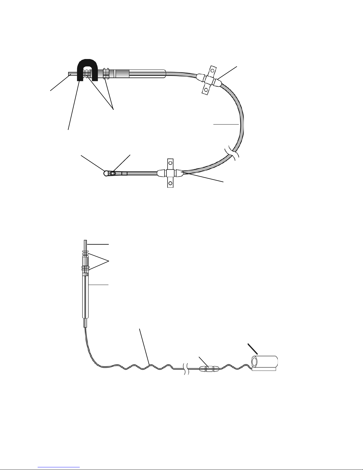
The implanted components of the Inspire therapy system consist of the Inspire II implantable
pulse generator (IPG) Model 3024, the stimulation lead model 4063, and the respiratory
sensing lead model 4323 (Figure 1).
Figure 1. Inspire system implanted components
When therapy is on, the Inspire system detects the patient’s respiratory effort and maintains
airway patency with mild stimulation of the hypoglossal nerve.
Therapy settings are stored in the IPG and configured by the physician using an external
programmer.
Stimulation lead
Respiratory
sensing lead
Implantable pulse
generator

8 English Inspire System Models 3024, 4063, 4323
200-079-101 Rev A
3024EN_ch.fm 5/6/14 10:31 pm
4.625 x 6 inches (117 mm x 152 mm)
Inspire Medical Confidential
The patient uses their Inspire sleep remote to turn therapy on before they go to sleep and to
turn therapy off when they wake up. The sleep remote also provides the ability to pause therapy
and adjust stimulation amplitude within physician defined limits.
Overview of the Manual
This manual provides physicians with implant procedure and follow-up care information for the
Inspire system. The manual includes instructions for handling, storing, and implanting the leads
and IPG. Critical therapy information is provided for you to discuss with your patient, as well as
instructions for follow-up care. General resterilization instructions for the IPG are also provided;
the leads cannot be resterilized. Information on explanting the IPG and leads is included. This
manual also explains how to register your patient's medical devices.
Sterile Package Contents
The leads and IPG are provided in separate sterile packages.
Inspire II Implantable Pulse Generator (Model 3024)
• One IPG
• One hex wrench
• Product literature (system implant manual, patient manual, patient registration form, and
patient ID card)

Inspire System Models 3024, 4063, 4323 English 9
200-079-101 Rev A
3024EN_ch.fm 5/6/14 10:31 pm
4.625 x 6 inches (117 mm x 152 mm)
Inspire Medical Confidential
Implanted Component Descriptions
The implanted components of the Inspire system consist of an IPG, a respiratory sensing lead,
and a stimulation lead. All implanted Inspire system components are intended for single-use
only.
IPG
The IPG (Figure 2) contains the battery and electronics that deliver Inspire therapy and store
the therapy settings.
Figure 2. IPG
The IPG has two 3.2 mm low-profile connector ports (Figure 3), which are compatible with the
connectors on the stimulation lead and the respiratory sensing lead. After inserting the lead
connectors into the IPG connector ports, the lead connectors are secured using the set screws
next to the connector ports.
Figure 3. IPG connector ports
STIM port
SENSE port
Top view
Side view
Set screw locations

10 English Inspire System Models 3024, 4063, 4323
200-079-101 Rev A
3024EN_ch.fm 5/6/14 10:31 pm
4.625 x 6 inches (117 mm x 152 mm)
Inspire Medical Confidential
Leads
The respiratory sensing lead (Figure 4) detects respiratory effort. The lead has a pressure-
sensitive membrane that converts the mechanical energy of respiration into an electrical signal.
Figure 4. Respiratory sensing lead
The stimulation lead (Figure 5) delivers stimulation to the hypoglossal nerve. The lead has a
flexible, self-sizing stimulation cuff. The stimulating electrodes are on the inner surface of the
cuff.
Figure 5. Stimulation lead
Shorting bar
Connector pin
Sealing rings
Lead body
Anchor: movable
Sensor tip
Anchor: fixed
Sensor membrane
Sealing rings
Self-sizing cuff
Connector
Anchor
Sigmoid lead body
Connector pin

Inspire System Models 3024, 4063, 4323 English 11
200-079-101 Rev A
3024EN_ch.fm 5/6/14 10:31 pm
4.625 x 6 inches (117 mm x 152 mm)
Inspire Medical Confidential
Contraindications
Contraindications for the use of Inspire UAS therapy include the following:
• Central + mixed apneas > 25% of the total apnea–hypopnea index (AHI)
• Any anatomical finding that would compromise the performance of upper airway
stimulation, such as the presence of complete concentric collapse of the soft palate
• Any condition or procedure that has compromised neurological control of the upper airway
• Patients who are unable or do not have the necessary assistance to operate the sleep
remote
• Patients who are pregnant or plan to become pregnant
• Patients who will require magnetic resonance imaging (MRI)
• Patients with an implantable device that may be susceptible to unintended interaction with
the Inspire system. Consult the device manufacturer to assess the possibility of interaction.
Adverse Effects
Possible adverse effects include, but are not limited to, the following patient related conditions:
• Damage to blood vessels in the vicinity of implant
• Excessive bleeding
• Nerve trauma or damage
• Allergic and/or rejection response to the implanted materials
• Infection
• Local irritation, seroma, hematoma, erosion, or swelling
• Persistent pain, numbness, or inflammation at the implant site
• Discomfort from the stimulation
• Tongue movement restrictions, irritation resulting from tongue abrasions on preexisting
sharp or broken teeth
• Tongue soreness or weakness
• Problems with swallowing or speaking
• Undesirable change in stimulation over time, possibly related to tissue changes around the
electrode(s), shifts in electrode position, loose electrical connections, or lead fractures
• Fibrosis to the extent that it makes it difficult to remove the system without damaging
surrounding structures
•Drymouth
• Other acute symptoms (i.e., headaches, coughing, choking, dysphasia, and speech
related events)
• Insomnia

12 English Inspire System Models 3024, 4063, 4323
200-079-101 Rev A
3024EN_ch.fm 5/6/14 10:31 pm
4.625 x 6 inches (117 mm x 152 mm)
Inspire Medical Confidential
Warnings and Precautions
Warnings
•Training— Physicians must be trained in the proper use and surgical procedure before
implantation or operation of the device.
•Pediatrics —The majority of cases of obstructive sleep apnea in younger pediatric
patients (e.g., less than 18 years of age) result from anatomical obstruction (e.g.,
adenotonsillar hypertrophy) that would not be appropriately managed with
neurostimulation therapy.
•Components — The use of components not provided by Inspire Medical Systems may
result in damaged components, improper operation, or increased risks to the patient.
•Diathermy — Do not use shortwave diathermy, microwave diathermy or therapeutic
ultrasound diathermy (all now referred to as diathermy) on patients implanted with a
neurostimulation system. Energy from diathermy can be transferred through the implanted
system and can cause tissue damage at the location of the implanted electrodes, resulting
in severe injury or death.
Diathermy can also damage the neurostimulation system components, resulting in loss of
therapy and requiring additional surgery for system explantation and replacement. Advise
your patient to inform all their health care professionals that they should not be exposed
to diathermy treatment.
Injury to the patient or damage to the device can occur during diathermy treatment when:
• The neurostimulation system is turned on or off
• Diathermy is used anywhere on the body—not just at the location of the
neurostimulation system
• Diathermy delivers heat or no heat
• Any component of the neurostimulation system (lead, extension, neurostimulator)
remains in the body
•Magnetic Resonance Imaging — The use of magnetic resonance imaging (MRI) among
IPG patients has been contraindicated by MRI manufacturers. Patients who have any
component of the Inspire system implanted should not undergo MRI. MRI can cause
tissue damage as well as damage to the Inspire system and components.
•Sleep remote use — When operating their Inspire sleep remote, patients should use
special care near flammable or explosive atmospheres. An interaction between the
flammable or explosive atmospheres and the battery in the sleep remote could occur. The
consequences of using the battery-powered sleep remote near flammable or explosive
atmospheres are unknown.
•Body Mass Index (BMI) —BMI greater than 32 was not studied as part of the pivotal trial.
Based on data from the feasibility study, it may be associated with decreased likelihood of
response to treatment. Use of Inspire UAS in higher BMI patients is not recommended due
to unknown effectiveness and safety.

Inspire System Models 3024, 4063, 4323 English 13
200-079-101 Rev A
3024EN_ch.fm 5/6/14 10:31 pm
4.625 x 6 inches (117 mm x 152 mm)
Inspire Medical Confidential
Precautions
General
•Pediatrics — The safety of implantation and the parameters for safe and effective
stimulation of the hypoglossal nerve have not been evaluated in clinical studies for patients
less than 22 years of age. There may be increased risk of nerve injury and stimulation-
related adverse events in this population, particularly in younger children (e.g., less than
12 years of age).
•Expiration date — Do not use any Inspire system product after its expiration date.
•Component handling — Precautions related to component handling during the implant
procedure are located on page 18.
•Storage temperature ranges
– Do not expose the IPG to temperatures above 52°C (125°F) or below -18°C (0°F).
– Do not expose the leads to temperatures above 55°C (131°F) or below -10°C (14°F).
Electromagnetic compatibility and medical procedures
For information on MRI and diathermy, see “Warnings” on page 12.
The IPG is designed to ensure immunity from most common sources of electromagnetic
disturbance. In most cases, turning off the electromagnetic disturbance source, or moving away
from the electromagnetic disturbance source will return the IPG to normal operation. Extremely
strong sources of electromagnetic disturbance could interfere with normal IPG operation,
causing the IPG to reset and requiring the IPG to be reconfigured. To reduce the possibility of
electromagnetic interference (EMI), patients are recommended to use therapy only while
asleep.
Medical environment
Electrocautery, irradiation, lithotripsy, RF-ablation, X-ray, and fluoroscopy are typical
electromagnetic disturbance sources in hospital and clinical environments. Medical treatments
that use ultrasonics, defibrillation, or radiation can adversely affect the Inspire system.
•Electrocautery — Electrocautery may induce failure of the IPG. Alternatives to
electrocautery should be used when available. Bipolar electrocautery should be used if
alternatives are not available. If electrocautery must be used in the vicinity of the IPG,
therapy should be turned off.
•Radiation therapy — The IPG should not be directly irradiated by therapeutic levels of
ionizing radiation (such as produced by cobalt machines or linear accelerators used for
cancer treatment) because of the risk of permanent damage to the IPG circuitry. If such
therapy is required in the vicinity of the IPG, shield the device and confirm its function after
treatment.
•RF-ablation — RF-ablation should not be used directly over the implant sites.
•X-ray and fluoroscopy — Exposure to diagnostic X-ray or fluoroscopic radiation should
not affect the IPG or leads.
•Therapeutic ultrasound — Exposure to high ultrasonic frequencies may result in damage
to the IPG or leads. It is not recommended to use high-output ultrasonic devices, such as
an electrohydraulic lithotriptor or bone growth stimulator on patients with an implanted IPG.

14 English Inspire System Models 3024, 4063, 4323
200-079-101 Rev A
3024EN_ch.fm 5/6/14 10:31 pm
4.625 x 6 inches (117 mm x 152 mm)
Inspire Medical Confidential
•Ultrasonic scanning — While there is no danger to the patient, ultrasonic scanning
equipment could cause mechanical damage to an IPG or leads if used directly over the
implant sites.
•Defibrillation — Defibrillation used anywhere on the patient’s body can cause permanent
damage to the IPG. Following defibrillation, the IPG should be interrogated to verify normal
operation.
Home or work environment
Based on laboratory tests of the IPG, the device should not be affected by the normal operation
of electrical equipment, household appliances, electric machine shop tools, microwave ovens,
internal combustion engines, low-powered radio, and microwave frequency transmitters. All
such equipment should be kept in good repair and properly grounded to avoid the possibility of
electrical shock or interference with the proper operation of the IPG.
Inspire therapy is intended for use during sleep only and should be turned off otherwise.
•Equipment operation — Patients should not operate potentially dangerous equipment,
such as power tools, during stimulation.
•Theft detectors — In general, theft detectors have been known to cause inadvertent and
potentially uncomfortable stimulation in neurological stimulation systems. Patients should
use care to avoid theft detectors and be aware in the presence of such systems.
•High-powered electric fields — Consult Inspire Medical Systems when the patient will
be in an area where contact with current carrying conductors is possible or near
high-powered electromagnetic fields radiated by arc welding units, induction furnaces,
induction stoves, resistance welders, radio or microwave frequency transmitters, etc.
•Mobile and cellular phones — Maintain a separation of at least 15 cm (6 in) between a
phone and the IPG.

Inspire System Models 3024, 4063, 4323 English 15
200-079-101 Rev A
3024EN_ch.fm 5/6/14 10:31 pm
4.625 x 6 inches (117 mm x 152 mm)
Inspire Medical Confidential
Storage and Handling
Recommendations for storage and handling of the IPG and leads are provided in this section.
Inspire Medical Systems sterilizes the IPG and leads with ethylene oxide (EtO) prior to
shipment.
Information about precautions for handling components is located on page 18.
IPG
Inspect the IPG and the lead sterile packages prior to opening. If the IPG package is damaged,
the IPG may be damaged as well. Return a damaged package to Inspire Medical Systems; see
the back cover of this manual for addresses.
Table 1. IPG Storage and Handling
Handling and Storage: Acceptable Unacceptable
Store and transport IPG within the
following environmental temperature
limits: -18°C (0°F) to +52°C (125°F).
A full or partial electrical reset condition
may occur at temperatures below
-18°C (0°F).
Do not implant the IPG if it has been dropped on
a hard surface from a height of 30 cm
(12 in) or greater.
Resterilization
Resterilization is not allowed.
• IPGs cannot be resterilized. If the
sterile package seal is broken, or if
the packages are otherwise
damaged, do not use.
• Return the package to your local
Inspire Medical Systems
representative, see back cover for
address.

16 English Inspire System Models 3024, 4063, 4323
200-079-101 Rev A
3024EN_ch.fm 5/6/14 10:31 pm
4.625 x 6 inches (117 mm x 152 mm)
Inspire Medical Confidential
Leads
If the lead sterile package seal is broken or the package is otherwise damaged, return the
package to Inspire Medical Systems. Leads cannot be resterilized.
Table 2. Lead Storage, Handling, and Resterilization
Handling and Storage: Acceptable Unacceptable
Store and transport leads within the
following environmental temperature
limits: -10°C (14°F) to +55°C (131°F).
Only use sterile-gloved hands to handle
the lead; rinse sterile surgical gloves in
sterile water before handling the lead.
Protect leads from materials that shed
lint and dust.
Exercise care and appropriate
instrument selection when handling the
stimulation lead cuff with a surgical
instrument.
Do not implant a lead that was dropped.
Avoid excessive traction or sharp instruments.
Avoid severe bending, kinking, stretching, or
handling with surgical instruments.
Do not immerse a lead in mineral oil or silicone
oil.
Do not expose the respiratory sensing lead to
static electricity.
Resterilization
Leads cannot be resterilized.
• If the sterile package seal is broken,
or if the packages are otherwise
damaged, do not use.
• Return the package to Inspire
Medical Systems; see the back
cover of this manual for addresses.

Inspire System Models 3024, 4063, 4323 English 17
200-079-101 Rev A
3024EN_ch.fm 5/6/14 10:31 pm
4.625 x 6 inches (117 mm x 152 mm)
Inspire Medical Confidential
Physician Training
Prior to implanting an Inspire system, surgeons will receive classroom instruction on Inspire
implant techniques as well as cadaver training. Sleep physicians and sleep technicians will
receive classroom instruction on how to titrate the device including hands on operation of the
programmer.
System Implant
This section describes a general implant procedure for the Inspire system.
Implantable Components
The Inspire system includes the following implantable components:
• Inspire II implantable pulse generator (Model 3024)
• Inspire respiratory sensing lead (Model 4323)
• Inspire stimulation lead (Model 4063)
The IPG has two lead connector ports (Figure 6). The connector port for the respiratory sensing
lead is marked SENSE. The connector port for the stimulation lead is marked STIM.
Figure 6. IPG and connector ports
STIM
SENSE

18 English Inspire System Models 3024, 4063, 4323
200-079-101 Rev A
3024EN_ch.fm 5/6/14 10:31 pm
4.625 x 6 inches (117 mm x 152 mm)
Inspire Medical Confidential
Procedure Overview
The implant procedure begins with preoperative planning. It is recommended that the
stimulation lead be the first Inspire component to be implanted. Secondly, a subcutaneous
pocket is created for the IPG. The connector end of the leads will be tunneled to this pocket.
After the stimulation lead is implanted, the respiratory sensing lead is implanted. After tunneling
the connector end of the leads to the IPG pocket, the leads are connected to the IPG and the
IPG is secured in the subcutaneous pocket.
Patient Preparation
• Ensure the tongue is visible during the surgical procedure in order to observe the response
to intraoperative test stimulation.
• The recommended body side for system implantation is the right side.
• Extend the patient’s right arm away from his or her side to allow access to the thorax for
respiratory sensor implantation.
• The patient's head and neck should be positioned to provide optimal access to the
hypoglossal nerve.
– Antimicrobial incise drape may be used.
– Use only short acting paralytic agent to preserve tongue response.
• A nerve monitoring system is recommended to locate the hypoglossal nerve and confirm
nerve recruitment.
• Surgical incisions are recommended to be made on natural skin creases to minimize
visible scarring.
• The patient should be given antibiotics preoperatively as well as postoperatively.
Surgical Materials
An Inspire system implant requires typical surgical equipment used during neck surgeries. The
following is a list of additional materials typically used during the system implant procedure:
• Sterile sleeve, bag or equivalent (to bring the telemetry cable into the sterile field)
• Right angled forceps or hemostat (for cuff electrode placement)
• A nerve monitoring and stimulation system (to locate the hypoglossal nerve and confirm
nerve recruitment)
Precautions for Handling Components
• The implanted components of this system should be carefully handled to avoid damage by
excessive traction or sharp instruments. Any component showing signs of damage should
not be used.
Caution: No instrument of any type should touch the sensor membrane. The
sensor membrane covers the sensor, the flat square recessed surface near the
tip of the respiratory sensing lead. Touching the sensor membrane will result in
damage to the sensor.

Inspire System Models 3024, 4063, 4323 English 19
200-079-101 Rev A
3024EN_ch.fm 5/6/14 10:31 pm
4.625 x 6 inches (117 mm x 152 mm)
Inspire Medical Confidential
Figure 7. Sensor membrane
– IPG drop — If the IPG is dropped more than 30 cm (12 in) onto a hard surface, it should
not be used.
– Setscrew cautions — Counterclockwise rotation of a set screw beyond one or two
revolutions while retracting it from the connector port may disengage the setscrew from
the connector block. Do not use any hex wrench other than the one packaged with the
IPG.
– Leads should be handled with great care at all times. Any severe bending, kinking,
stretching, or handling with surgical instruments may cause permanent damage to the
lead body or the cuff. Do not implant a lead that was dropped.
– Lead insulators attract small particles, such as lint and dust; therefore, to minimize
contamination, protect the lead from materials shedding these substances. Handle the
lead with sterile surgical gloves that have been rinsed in sterile water.
– Do not immerse leads in mineral oil or silicone oil.
•Static electricity — The respiratory sensing lead is sensitive to static electricity.
Therefore, the shorting bar should be left in place and removed just prior to implant.
Cautions:
• The black, U-shaped shorting bar must not be removed except during
tunneling and immediately prior to connecting the lead to the IPG.
• After tunneling, if the lead is not immediately connected to the IPG, the black,
U-shaped shorting bar must be reattached.
Sensor membrane

20 English Inspire System Models 3024, 4063, 4323
200-079-101 Rev A
3024EN_ch.fm 5/6/14 10:31 pm
4.625 x 6 inches (117 mm x 152 mm)
Inspire Medical Confidential
Stimulation Lead Implant
The stimulation lead is designed with a cuff that is placed around the hypoglossal nerve after
the nerve is exposed.
The following is an overview of the recommended process for implanting the stimulation lead:
• Expose the hypoglossal nerve (see “Exposing the hypoglossal nerve” below).
• Place the cuff around the nerve and irrigate the cuff and nerve with sterile saline.
• Test the electrode placement using the IPG or an external nerve stimulator.
• Secure the stimulation lead anchor to the digastric muscle with permanent sutures.
• Form the IPG pocket and tunnel the lead connector to the pocket.
Exposing the hypoglossal nerve
1. Make a 4–6 cm (1.6–2.5 in) incision along a natural skin crease from
3–4 cm (1.2–1.6 in) below the right edge of mandible.
2. Retract the submandibular gland cephalad.
3. Identify the digastric muscle, and carefully dissect in the submandibular triangle to identify
the hypoglossal nerve.
4. Once the nerve is identified, it may be stimulated at a low setting (for example 0.5 mA)
using an external nerve stimulator to confirm nerve function. Do not over stimulate the
nerve with the external device.
5. Expose 1–2 cm (0.4–0.8 in) length of the hypoglossal nerve.
Placing the stimulation lead
To place the stimulation lead cuff, the cuff’s short inner and long outer flaps (Figure 8) are
wrapped around the hypoglossal nerve.
Figure 8. Stimulation lead cuff flaps
Cautions:
• Do not apply tension to the nerve and supporting tissue while exposing the
nerve and placing the cuff.
• Preserve the small nutrient blood vessels along the nerve fibers.
• Maintain hemostasis. Fluid residuals increase the chances of hematoma
formation and infection.
Long outer
flap
Short inner
flap
Electrodes
This manual suits for next models
1
Table of contents
Other Inspire Personal Care Product manuals