IMPORTANT: READ CAREFULLY BEFORE ASSEMBLY AND USE.
Mounting
Permanent Mounting
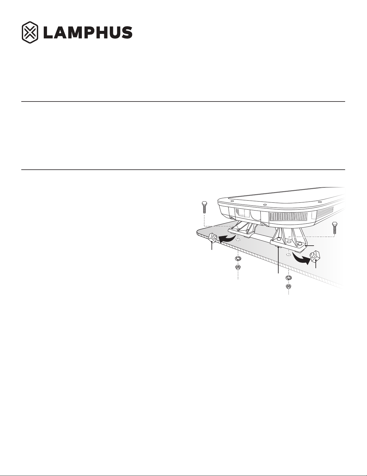
Mounting Diagram #1
Installer of this product must have a good understanding of automotive electronics,
systems, and procedures.
In the case that holes must be drilled in order to properly mount the product, the installer
must examine both sides of the mounting surface before drilling begins. It is the
installer’s responsibility to be sure that no vehicle components or vital parts could be
damaged by the drilling process. De-burr any holes in order to remove metal shards and
remnants. Use grommets in all wire passage holes.
If this manual states that this product may be mounted with suction cups, magnets,
tape, or Velcro®, clean the mounting surface and dry thoroughly prior to applying any
adhesives for maximum adhesion.
Do not attempt to activate or operate this product under hazardous driving situations.
1.
2.
3.
4.
5.
6.
7.
8.
9.
10.
11.
12.
13.
14.
15.
Turn the light bar upside down to gain access to the fasteners holding the two mounting
feet to the light bar. There is a total of 8 fasteners; 4 per mounting foot.
Slightly loosen the nuts fastening the two mounting feet to the light bar so both the
mounting feet can be adjusted alongside the light bar. There are 4 nuts per mounting foot.
Remove the center mounting pad located on the two ends of each of the mounting foot.
Totaling 4 mounting pads. This opening will be where the mounting bolt would be inserted
to permanently mount the light bar onto the roof of the vehicle. Refer to Mounting
Diagram # 1.
Return the light bar to its right side up position.
Select a desired mounting location on the roof of the vehicle. Consider mounting the light
bar above the B-pillars as this is often the location of the roof which the strongest
structural support is present.
Position the light bar over the roof of the vehicle onto the desired mounting location.
Adjust the two mounting feet alongside the light bar to position the mounting pads as
close to the edge of the roof as possible. Make sure that all mounting pads are in contact
with the roof of the vehicle and that there is at least 1/2” of space between the bottom of
the light bar and the roof of the vehicle.
Once the light bar and its mounting feet are properly positioned, slightly tighten the nuts
fastening the two mounting feet to the light bar and mark the position of where the
mounting holes on the vehicle’s roof are to be drilled.
Remove the light bar from the roof and turn it upside down.
Proceed on tightening the 8 nuts fastening the 2 mounting feet to the light bar.
Return the light bar to its right side up position.
Place light bar over the roof of the vehicle over its desired mounting location one more
time to make sure the holes on the mounting feet are still aligned with the markings made
in step # 8.
Remove the light bar from the roof and adjust the position of the mounting feet
if necessary.
If the mounting feet and the desired mounting holes align properly while performing step
12, proceed on drilling the mounting holes onto the roof of the vehicle. De-burr all holes.
Place the light bar onto the roof and proceed on fastening the light bar onto the vehicle
using the included hardware. Refer to Mounting Diagram # 1.
Strap/Gutter Bracket Mounting
1.
2.
3.
4.
5.
6.
7.
8.
Turn the light bar upside down to gain access to the fasteners holding the two
mounting feet to the light bar. There is a total of 8 fasteners; 4 per mounting foot.
Slightly loosen the nuts fastening the two mounting feet to the light bar so both the
mounting feet can be adjusted alongside the light bar. There are 4 nuts per
mounting foot.
Return the light bar to its right side up position.
Select a desired mounting location on the roof of the vehicle. Consider mounting the
light bar above the B-pillars as this is often the location of the roof which the
strongest structural support is present.
Position the light bar over the roof of the vehicle onto the desired mounting location.
Adjust the two mounting feet alongside the light bar to position the mounting pads
as close to the edge of the roof as possible. Make sure that all mounting pads are in
contact with the roof of the vehicle and that there is at least 1/2” of space between
the bottom of the light bar and the roof of the vehicle.
Open the doors of the vehicle.
Position the mounting straps on to the door gutter of the vehicle while estimating
which hole should be used to affix the mounting strap to the mounting strap
L-bracket with the included bolt, washer, split washer, and nut.
•
•
•
•
Deployment area of the vehicle air bags must be cleared. Do not install this product
or route any electrical wires near the air bags deployment areas. Refer to your
vehicle owner’s manual for the air bag deployment area. Products or wires mounted
in the air bag deployment area will damage, reduce the effectiveness of the air bag,
or even act as a projectile which may cause serious injury or death. The user/installer
of this product assumes full responsibility in determining the proper mounting
location while prioritizing the safety of all passengers in the vehicle.
This product contains strobe light(s), halogen light(s), high-intensity LEDs, or a
combination of these components. Do not look directly into the lights. Momentary
blindness and/or injury to the eyes could result.
•
•
Pg. 1
Mounting Surface
Remove
Remove
Mounting Feet
Mounting Pads
Mounting Pads
Mounting Pads
SolarBlast LED Full Size Light Bar
www.truemods.com
US Toll Free: 1-855-533-6654
International: 1-909-212-0993
Fax: (909) 575-6722
Manual ID: PIM-00000065-V002
IMPORTANT! The light bar should NOT be placed within 16” from any radio antennas.
CAUTION! Removal of the headliner may be necessary when permanent mounting this
product. There may be a roof support beam which runs from the driver’s to the passenger’s
side of the vehicle. Do NOT drill through this support beam. Permanent mounting of this
product will require drilling. It is absolutely necessary to make sure that no other vehicle
components could be damaged by this process. Check both sides of the mounting surface
before starting. If damage is likely, select a different mounting location.
True Mods © 2012-2023 All Rights Reserved


