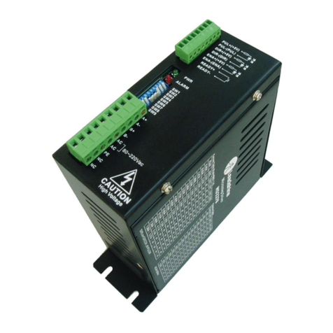
SIEBE Satchwell CZT User manual

DS 2.105
10/97
CZT
PROPORTIONAL CONTROLLER
Specification No. 562-5-305
The CZT is designed for use in systems such as room or return water
control. The CZT can be used for single or two stage control. The CZT
is suitable for use with 0 to 10Vdc actuators and/or step controllers.
The controller is designed to be simple to install and easy to use. The
controller is used in simple plants typically in schools, libraries and
large domestic installations. It may be installed either within a control
panel or can be wall mounted.
The large Liquid Crystal Display (LCD) is used to recall plant status,
temperature values and for programming the controller. The user can
recall, display and adjust parameters quickly and easily, prompted by
the controller display. The facia has clearly labelled push-buttons for
use when setting the controller. There is an overlay card which must
be placed over the controller display for use in Fine Tune Mode. A
rotary selector switch is provided to enable overrides to be quickly and
easily applied.
The CZT is shipped with standard (default) values for parameters.
These default settings are used so that in most cases only a minimal
number of parameters need to be amended to get the best out of the
controller. It is important, however, that you tune the CZT to your
control system to get the best out of it. Typical default values that need
to be checked/set are:-
Actuator ramp speed
Controller tuning
FEATURES
•Easy to install and commission.
•Shipped with typical default values for the parameters,
decreasing commissioning time.
•Quick Set Mode allows basic settings to be easily checked and
set.
•Simple override switch.
•Operates one or two stage systems.
•Standard 0 to 10Vdc output.
•Large Liquid Crystal Display (LCD) for viewing plant status/
temperature and controller parameters.
•Two setting modes available (Quick Set and Fine Tune) so that
users are only presented with the required parameters.
•Night Set Back (NSB) and Set-Up inputs.
•Existing CZT sensors can be used.
•Remote set value from an RPW.

DS 2.105 2 - 12 10/97
SPECIFICATIONS
OUTPUTS
Control Outputs: 2 x 0 to 10Vdc outputs for heating and cooling.
Output Supply: 2 x 24Vac terminals used to power the actuator(s) up
to a total of 10VA maximum. If more than 10VA is required use an
external 24Vac transformer conforming to EN 60742, see Fig. 9 for
wiring details.
Notes:-
1. All 0 to 10Vdc outputs are protected against accidental short circuit
to 24Vac and ground.
2. Short circuit current of each 0 to 10Vdc output approximately
8.5mA (source resistance is approximately 1500 Ohms).
3. Load resistance for each 0 to 10Vdc output must be equal to or
greater than 10k Ohms.
4. The maximum current that a 0 to 10Vdc output can source is 1mA.
5. New generation sensors should be used on all new installations.
SENSOR INPUTS
"T" type (new Generation) sensors may not be mixed with old
generation sensors on the same CZT.
SWITCHED INPUTS
Night Set Back (NSB): Voltage Free, Make/Break contacts.
Normally Closed.
Set Up: Voltage Free, Make/Break contacts. Normally Closed.
CONSTRUCTION
Memory
The controller stores all non-volatile data in an E2PROM such as the
user set control parameters. This means that in the event of a power
failure the user set parameters willbe maintained without having to rely
on battery support.
INSTALLATION AND COMMISSIONING
The CZT should be installed and commissioned by a competent
technician.
DO NOT SWITCH ON THE POWER SUPPLY UNTIL THE
COMMISSIONING PROCEDURES HAVE BEEN COMPLETED.
Location of Controller
•The controller must be installed in a position which is fairly clean and
free from damp and condensation.
•Temperature and humidity limits must be obeyed
Ambient Operating Temperature: 0°C to 50°C
Operating Humidity: 0 to 95% RH non condensing
•A minimum of 150 mm clearance is required around the controller to
allow access for mounting, wiring, servicing and to avoid electrical
interference from other devices such as contactors.
Wiring Precautions
•On new installations all sensor cables must be screened with the
screens connected separately to the 0V earth point provided. An
MICC earth plate is provided for use if MICC cable is used.
•When upgrading an old CZT installation it is usually possible to use
the existing unscreened sensor wiring as long as the cable run is
less than 100 metresand is sited more than75mm from mains wiring
runs.
•The mains supply, 24Vac output and triac output wiring must be run
separately from all the controller sensor and override inputs.
•The controller must be located as far away as possible (minimum
150mm) from any contactors or switchesand their cables. This is to
avoid any interference to the controller.
•No connections to the controller should be made whilst power is
applied.
Compatible Sensors
There are a large number of Satchwell sensors that are compatible
with the CZT (see Sensor Inputs).
It is not possible to mix old and new generation sensors on the
CZT.
The first time the CZT is powered up it will automatically configure itself
to the sensor type connected (old or new generation).
Changing Sensors
If a CZT connected to old generation sensors is subsequently
equipped with a set of 'type' sensors it is necessary to manually select
the sensor type as 5 (new generation).
Remember that you cannot mix new and old generation sensors on the
CZT.
COMMISSIONING
ENSURE THE MAINS POWER SUPPLY IS OFF AND THAT ANY
OTHER POWER SUPPLIES TO AND FROM THE CZT ARE
ISOLATED.
1. Undo the central case fixing screw and separate the case to gain
access to the terminals.
2. Check that all wiring is correctly connected to the terminals. This
should be done using the connection or application diagram for
reference.
3. Reassemble the controller case and securely tighten the central
fixing screw.
4. Apply mains power to the controller, the display will show reset
followed by the controller firmware number.
5. The controller will then go into review mode.
6. Complete the configuration via the Quick-Set and Fine-Tune
parameters.
7. If an RPW is wired to the CZT, parameters SV1 and SV2 in Quick
Set Mode will be ignored. In this case the heating and cooling set
values are determined by adding and subtracting 1°C to/from the
RPW position, e.g. If the RPW is set to 20°C, the heating set value
will be 19°C and the cooling set value will be 21°C.
Reasonable default values have been selected for the CZT, but it is
essential that the controller is properly tuned to the controlled system.
Typical default values that should be checked/set are:-
The number and type of output stages
Controller tuning
Actuator Ramp Speed
Type: CZT 5305 – One or two stage, 0 to 10Vdc output, proportional controller -
Specification No. 562-5-305
Power Supply: 230Vac, +10%, -6% (50/60Hz)
Power Consumption: 22VA fully loaded
Fuse: 100mA on the 230Vac input
NEW GENERATION SENSORS PREFERRED
Sensor Sensor Type Temperature Range
DRT 3651, 3453, 3451 Room –5 to 40°C
DDT 1701, 1702 Duct –5 to 100°C
DWT 1701, 1702 Water –10 to +120°C
DST 1601 Water (strap on) +5 to +120°C
RPW 4425 Remote Set Value +10 to +35°C
Ambient Temperature
Limits: Operating: 0°C to 50°C
Storage: –10°C to 70°C
Ambient Humidity Limits: Operating: 0 to 95% RH non
condensing
Storage: 0 to 95% RH non condensing
Terminals: The terminals are provided to take wire
of 2.5mm2cross-section.
Conduit Entries: Six, 21mm cut-outs in the top and
bottom of the controller case.
Protection Class: IP 30
Case: Matt black coloured 2 piece
polycarbonate case. Fire resistant to
UL94V-0.
Mounting: Wall or flush panel mounting.
Case Dimensions: 144 x 144 x 136mm
Panel Cut Out Size: 138 x 138mm

10/97 3 - 12 DS 2.105
RELOADING THE DEFAULT VALUES
DISPLAY AND SETTINGS
A Large Liquid Crystal Display (LCD) is used for the display of
controller status temperatures and the setting of parameters. Arrows
aroundthe displayindicatecontrollerstatusandindicate theparameter
currently being displayed/set. The controller works in three modes:
Review Mode
The controller usually operates in Review Mode, this allows the
operator to view various system temperatures, the controller output
status and the current set value. No changes may be carried out in this
mode.
Quick Set Mode
Quick Set Mode allows various basic controller functions to be set.
Fine Tune Mode
Fine Tune Mode allows the more advanced controller functions to be
set. When using Fine Tune Mode an overlay card is used that gives
the fine tune parameter symbols.
Facia
The following figure shows the CZT facia.
The four buttons have the following functions:
The unmarked button is not used.
Manual Overrides
A simple rotary switch, shown below, is used to select the override
function.
THIS SWITCH CAN BE SET IN ANY MODE INCLUDING REVIEW
MODE.
IT IS IMPORTANT TO REMEMBER TO SWITCH BACK TO AUTO
AFTER THE MANUAL OVERRIDE FUNCTION HAS BEEN USED.
WHEN THE SWITCH IS IN AN OVERRIDE CONDITION THE
DISPLAY WILL FLASH.
The modes are as follows:
This procedure only needs to be carried out if you need to reload the
controller default values. The controller will also automatically
configure itself to the sensors connected to it.
The following procedure will reload the CZT default values.
THIS WILL DELETE ALL YOUR EXISTING USER SETTINGS.
1. Switch OFF the power.
2. Press and hold the "Enter" key. Switch the power ON.
3. The controller display will show "reset" followed by the firmware
number.
4. The controller will now display "dflts". Release the "Enter"
key.
5. The controller display will shown "reset" again followed by the
firmware number.
6. The controller will then go into review mode.
TuningButton: Selectsthemodethatallowssettingof the
controller parameters.
Enter Button: Enter button for confirming the entry of
parameters.
Plus Button: To increase the value or move clockwise to
the next function. Holding the button down will cause it to
auto repeat.
Minus Button: To decrease the value or move anti-
clockwisetothenext function. Holdingthebuttondownwill
cause it to auto repeat.
Liquid
Crystal
Display
Rotary
Override
Switch
Fig.1
Fixing
Screw
Setting
Buttons
AUTO Auto mode: Allows the controller to operate automatically
and uses all of the set parameters.
Cooling ON: Forces the cooling actuator to open and
closes the heating actuator.
Actuator(s) Close: The actuators are forced closed (0V).
Heating ON: Forces the heating actuator to open and
closes the cooling actuator.

DS 2.105 4 - 12 10/97
Review Mode
The review mode is a read only display mode. It shows various
temperatures and the status of the actuator(s).
No settings can be changed in this mode, except the facilities on the
manual override switch.
The main display will show the main sensor reading by default.
Press the button before trying to move the cursor.
By pressing the or buttons the display will show the CZT
parameters in turn with the appropriate symbol highlighted by the
display arrow. The button moves the cursor clockwise and the
button moves the cursor anti-clockwise.
Setting the Default Display for Review Model
Move the cursor arrow to the required parameter and press the
button, the arrow will stopflashing. You have now selected the default
parameter to be displayed when the CZT returns to Review Mode.
The controller functions available for viewing in Review Mode are as
follows:
Accessing and Exiting Quick Set Mode
The user settings that are able to be adjusted or viewed in the Quick Set Mode are:
How To Set Values
This method applies to all parameters
Symbol Description
Valve Opening
Valve Closing
Display Actual Sensor Temperature
Display RPW Setting
Display Calculated Set Value
1. Press andholdthe button and then the button,keeping
both buttons pressed down untilSEC appears on the display. This
means that mode selection has been accessed.
2. Press the 'tuning key' button followed by the 'enter'
button to access the Quick Set Mode.
3. The display will show the arrow pointing towards the 'tuning
graphic' on the left side of the display.
4. To exit Quick-Set Mode the 'tuning key' button must be
pressed when the icons are flashing. If no keysare pressed within
30 seconds the controller will return to the default review mode.
Symbol Description Used In Default Range
Tuning Key
Indicates that you are in Quick Set Mode if the arrow is lit. Quick Set
Mode ––
SV1 Set Heating Stage Set Value
The heating set value must never be set higher than the cooling stage set value. If a
deadzone is required then the heating stage set value must be set lower than the cooling
stage set value, the difference between the two gives the deadzone. Using an RPW will
cause this set value to be ignored. In this case the heating set value is determined by
subtracting 1°C from the RPW position, e.g. If the RPW is set to 20°C, the set value will be
19°C.
Quick Set
Mode 20 0 to 255°C
Pb1 Set Heating Stage Proportional Band
Determines the temperature range over which the actuator output goes from closed to
open.
Quick Set
Mode 10 0 to 255K
SV2 Set Cooling Stage Set Value
The cooling set value must never be set lower than the heating stage set value. If a
deadzone is required then the heating stage set value must be set lower than the cooling
stage set value, the difference between the two gives the deadzone. Using an RPW will
cause this set value to be ignored. In this case the cooling set value is determined by
adding 1°C to the RPW position, e.g. If the RPW is set to 20°C, the cooling set value will be
21°C.
Quick Set
Mode 22 0 to 255°C
Pb2 Set Cooling Stage Proportional Band
Determines the temperature range over which the actuator output goes from closed to
open.
Quick Set
Mode 10 0 to 255k
RS Set Actuator Ramp Speed
Sets the time the actuator takes to move from closed to fully open given a continuous
demand.
Quick Set
Mode 100 0 to 255
Seconds
1. Enter Quick Set Mode as previously described.
2. When in theQuick Set Mode, anarrow will appearand the required
symbol can be selected by scrolling left or right using the and
buttons.
3. When the parameter is highlighted press the 'enter' button.
This allows the value to be adjusted, using the and
buttons.
4. Press the 'enter' button when the required value is
displayed. This will enter the value. If you decide not to change
the value press the 'tuning' button instead.
5. The display will clear, but the arrow will continue to flash at the
selected symbol.
6. To return to review mode at any time press the 'tuning'
button until the review mode appears.

10/97 5 - 12 DS 2.105
Overlay Card Printing, Fine Tune Mode Only
Entering and Exiting The Fine Tune Mode
The Fine Tune Mode is used by Commissioning Engineers and the
more advanced users to set the Fine Tune parameters.
The overlay card must be placed on the CZT to use the Fine Tune
mode.
The user parameters that can be viewed and/or adjusted in the Fine Tune Mode are:
Fig.2
1. Press and hold the button and then the button, keeping
both buttons pressed down until 'SEC' appears on the display.
This means that mode selection has been accessed.
2. Press the 'tuning' button three times. The display will show
'CARD 1' and all thearrows will flash simultaneously on the screen
to show that the Fine Tune Mode is being entered. Place the
overlay card on the display. The overlay card has a different set of
symbols for the arrows to point to. Press the 'enter' button.
3. The display will show a flashing arrow pointing towards the
‘tuning’ graphic on the left side of the display.
4. Parameters are set in the same way as in Quick Set Mode.
5. To exit Fine Tune Mode at any time press the 'tuning key'
button. If no keys are pressed within a period of 30 seconds then
the product will return to the Review mode.
Symbol Description Used In Default Range
Tuning Key
Indicates that you are in Fine Tune Mode if the arrow is flashing. Fine Tune
Mode ––
I1 Set Integral Action Time Heating
Sets the integral action time for the heating stage between 0 and 2550 seconds. Fine Tune
Mode 0 0 to 2550
Seconds
d1 Set Derivative Action Time (seconds) Heating
This is usually set to 0. Derivative action is used when faster control action is required and
reducing the Pb1 and/or I1 causes hunting.
Fine Tune
Mode 0 0 to 255
Seconds
I2 Set Integral Action Time Cooling
Sets the integral action time for the cooling stage between 0 and 2550 seconds. Fine Tune
Mode 0 0 to 2550
Seconds
d2 Set Derivative Action Time (seconds) Cooling
This is usually set to 0. Derivative action is used when faster control action is required and
reducing the Pb2 and/or I2 causes hunting.
Fine Tune
Mode 0 0 to 255
Seconds
Set Temperature Set Up Value
Sets the amount the temperature should be increased by during set up. Fine Tune
Mode 10 0 to 255K
Set Night Set Back Value (NSB)
Sets the amount the temperature should be decreased by during NSB. Fine Tune
Mode 10 0 to 255K
Sensor Averaging
This tells the CZT how many Room sensors are connected to it for averaging. It is possible
to have between 1 and 4 room sensors on the CZT.
Fine Tune
Mode 11to4
Set Sensor Type
The sensor type is normally automatically detected when the CZT is first powered up but
it can manually set if required.
Fine Tune
Mode –1,4or5
1→ 2Select the number/type of Output Stages
0 = Two Stage Heating/Cooling
1 = Single stage Heating
2 = Single Stage Cooling
See wiring diagrams for examples. If more than one stage is used the total stroke time of
all of the output actuators should be set in Ramp Speed (RS).
Fine Tune
Mode 00to2

DS 2.105 6 - 12 10/97
TYPICAL APPLICATIONS
SINGLE STAGE HEATING OR COOLING
The CZT can operate in single stage heating or cooling mode to
control, for instance, room temperature.
Set the control output type to:-
1 for single stage heating
2 for single stage cooling
By using an RPW the CZT set value can be set from a remote point.
The CZT also has a set-up and set-back input to modify the controller
set value from a time switch or other remote contact.
Outside Air
Frost
Fig.3
Thermostat
Fig.4
Set-up
Night Set-back
Links 7-8 and/or 9-10 must be
removed if Set-up and/or Night
Set-Back is used.
Maximum 24Vac output from
CZTis10VA.Ifmorethan10VA
is required use a separate
transformer conforming to EN
60742.
See Fig.9.
If DRT 3651 is used
please see Fig.11.

10/97 7 - 12 DS 2.105
TWO STAGE HEATING AND COOLING
The CZT can operate in two stage heating and cooling mode to control,
for instance, room temperature.
Set the control output type to:-
0 for two stage heating and cooling
By using an RPW the CZT set value can be set from a remote point.
The CZT also has a set-up and set-back input to modify the controller
set value from a time switch or other remote contact.
Outside Air
Fig.5
Fig.6
Set-up
Night Set-back
Links 7-8 and/or 9-10 must
beremovedifSet-upand/or
Night Set-Back is used.
Maximum 24Vac output
from CZT is 10VA. If more
than 10VA is required use a
separate transformer
conforming to EN 60742.
See Fig.9.
If DRT 3651 is used
please see Fig.11.

DS 2.105 8 - 12 10/97
BOILER SEQUENCE SCHEME CONTROLLED FROM RETURN WATER TEMPERATURE
The CZT can be used to control a step controller to sequence, for
instance, boilers. In the case of boiler sequence control the system
temperature is monitored and controlled from the return water
temperature so that boilers will be less likely to short cycle.
Set the control output type to:-
1 for single stage heating
By using an RPW the CZT set value can be set from a remote point.
The CZT also has a set-up and set-back input to modify the controller
set value from a time switch or other remote contact.
Flow to Heating
Circuit
Return from
Heating Circuit
Control/Limit
Thermostats
Manual Lead
Selector Switch
Backend
Valve
Backend
Valve Backend
Valve
Shunt Pump
Pump
Fig.7
Fig.8
Links 7-8 and/or 9-10
mustberemovedifSet-up
and/or Night Set-Back is
used.
C=Common
- = Backend Valve Close
+ = Backend Valve Open
Auxiliary switch contacts
make when valve is open
to enable boiler.
VZ/VZF valves can be
used as backend valves
or third valves may be
used.
Manual lead selector
switch not supplied by
Satchwell.
Boiler Control/Limit
Thermostats
Manual Lead
Selector
Switch
Backend Valve
Actuators fitted
with Auxiliary
Switches
To Boiler Burners
BEFORE WIRING EQUIPMENT ENSURE THAT ALL
SUPPLIES ARE ISOLATED. MAINS VOLTAGE
ISOLATORS MUST CONFORM TO EN 60335-1

10/97 9 - 12 DS 2.105
CONNECTION TO A SEPARATE TRANSFORMER IF MORE THAN 10VA IS REQUIRED FROM THE CZT
SENSOR AVERAGING (UP TO 4 SENSORS)
USING THE DRT 3651 WITH THE CZT CZT OVERRIDE
Fig.9
NOTE: The independent
24Vtransformersecondary
should be fused and must
conform to EN 60742.
Independent 24V
Transformer
Fig.10
Set the number of room sensors
connected on the Fine Tune Mode.
NOTE: 3 Cores are required to enable full
functionality Fig.11
Normal Override
19 supplies a signal to the Heating actuator.
20 supplies a signal to the Cooling actuator.
35 supplies 0V to override the actuator.
Fig.12

DS 2.105 10 - 12 10/97
MAINTENANCE
A periodic system and tuning check of the control system is
recommended.
WIRING PRECAUTIONS
The controller must be located as far away as possible (minimum
150mm) from any contactors or switches and their cables. This is to
avoid any interference to the controller.
1. All 0 to 10Vdc outputs are protected against accidental short circuit
to 24Vac and ground.
2. Short circuit current of each 0 to 10Vdc output approximately
8.5mA (source resistance is approximately 1500 Ohms).
3. Load resistance for each 0 to 10Vdc output must be equal to or
greater than 10k Ohms.
4. The maximum current that a 0 to 10Vdc output can source is 1mA.
No connections to the controller should be made whilst power is
applied.
WiringfromCZTcontroller
to: Maximum
unscreened
length
Maximum
resistance per
core
Sensors, RPW Screened Only*
* On new installations all sensor cables must be screened with the screens
connected separately to the 0V earth point provided, however when upgrading
an old CZT installation it is usually possible to use the existing unscreened
sensor wiring as long as the cable run is less than 100 metres and is sited
more than 75mm from mains wiring runs.
The mains supply, 24Vac output, relay and triac output wiring must be run
separately from all the controller sensor and override inputs.
15 Ohms
Actuators
ARE, ALE, ALES, AVUE
24Vac Supply
0 to 10Vdc positioning
signal
100m
100m 3Ohms
50 Ohms
Step controllers
FLS, TSU Screened Only 50 Ohms
Relays, ON/OFF Inputs Screened Only 5 Ohms
Power Supply 230Vac Screened Only –
For runs over 100m up to 300m maximum use one of the following screening
options:
•Screened cable. Earth screen at the controller end only.
•MICC. Earth screen at controller end only

10/97 11 - 12 DS 2.105

DS 2.105 12 - 12 10/97
Satchwell Control Systems Limited
Farnham Road
Slough
Berkshire SL1 4UH
United Kingdom
Telephone +44 (0)1753 550550
Facsimile +44 (0)1753 824078
A Siebe Group Company © 1997 Satchwell Control Systems Limited (revised October 1997)
All rights reserved. Unauthorised copying of any part of the contents is prohibitied.
Printed in England. 10/97
DIMENSION DRAWING
3-21mmØ
conduit
entries
PANEL CUT-OUT
138mm x 138mm
Weight 1.5 kg
3-21mmØ conduit entriesDimensions in mm
CAUTION
•This is a mains operated device. Local wiring regulations and
usual safety precautions must be observed. Note earthing
requirements.
•Observe wiring precautions on Page 10.
•Do not switch on the power supply until commissioning on
Page 2 has been carried out.
•Do not short circuit sensor terminals for test purposes.
•Observe ambient temperatures and humidities shown on Page 2.
•Interference with those parts under sealed covers renders the
guarantee void.
•Design and performance of Satchwell equipment are subject to
continual improvement and therefore liable to alteration without
notice.
•Information is given for guidance only and Satchwell does not
accept responsibility for the selection or installation of its products
unless information has been given by the Company in writing
relating to a specific application.
•A periodic system and tuning check of the control system is
recommended. Please contact your local Satchwell service office
for details.
Table of contents
Other SIEBE Controllers manuals
