Bodine Quality IN Motion 0810 User guide

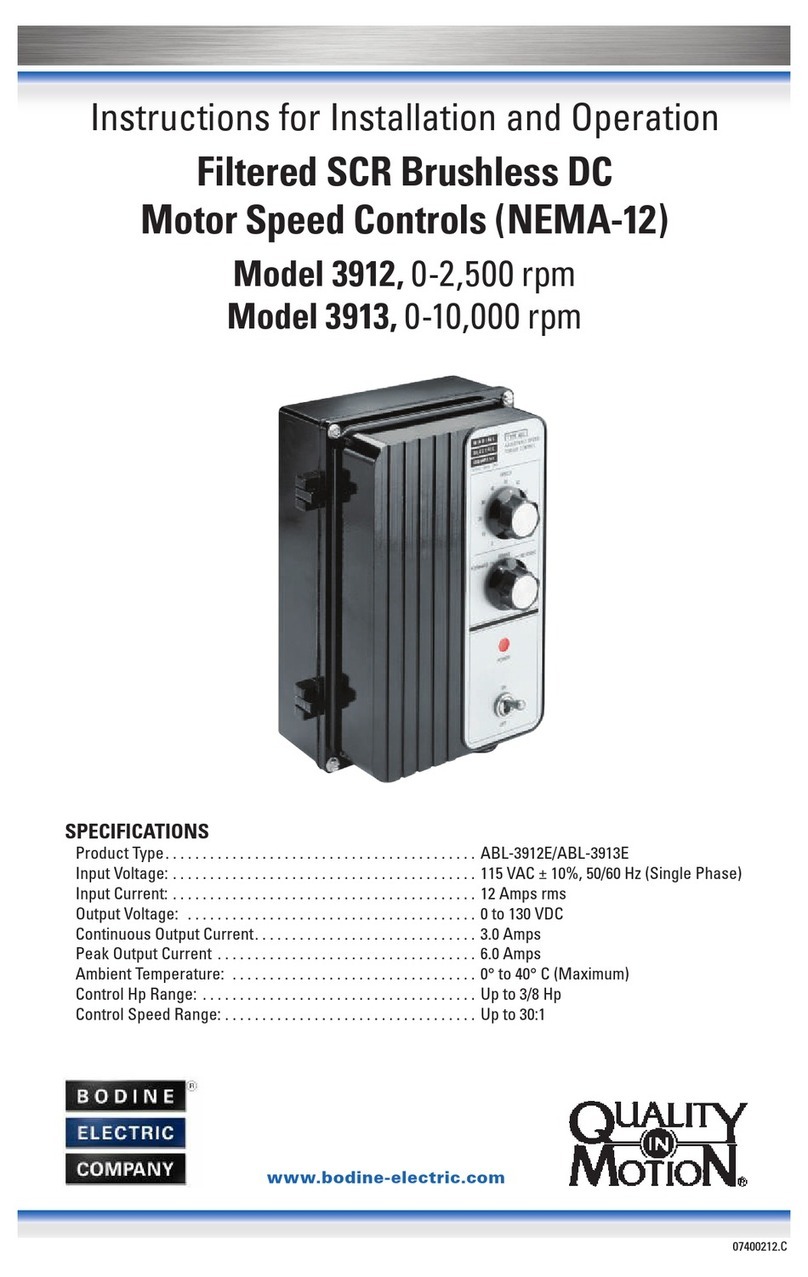
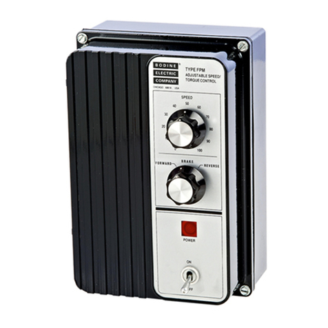
Type FPM 0810, 0830, and 0850
Permanent Magnet DC Motor Controls
(with driver board only, or with F-B-R board)
Model 0810 up to 1/17 HP
Model 0830 up to 1/6 HP
Model 0850 up to 1/3 HP
SPECIFICATIONS
Input Voltage: ...................115 VAC±10%; 50/60 Hz, single phase
Input Current:
Model 0810........................................ 2.9 Amps AC
Model 0830........................................ 4.2 Amps AC
Model 0850........................................ 9.0 Amps AC
Armature Voltage (nominal) ............................. 0-130 VDC
Armature Current (max. continuous)
Model 0810..........................................0.50 Amps
Model 0830.......................................... 1.25 Amps
Model 0850..........................................2.30 Amps
07400156.i
www.bodine-electric.com
Instructions for Installation and Operation

2
© 2023 Bodine Electric Company.
All rights Reserved. All data subject to change without notice. Printed in U.S.A.
BODINE LIMITED WARRANTY
The Bodine Electric Company warrants all products it manufactures to be free
of defects in workmanship and materials when applied in accordance with
nameplate specifications. Bodine motors and gearmotors purchased with
and used only with appropriately applied Bodine controls are covered by this
warranty for a period of 24 months from the date of purchase or 30 months from
date of manufacture, whichever comes first. Bodine motors and gearmotors
used with non-Bodine controls and Bodine controls used with non-Bodine
motors and gearmotors are covered by a 12 month warranty period. The Bodine
Electric Company will repair, replace, or refund at its option, any of its products
which has been found to be defective and within the warranty period, provided
that the product is shipped freight prepaid, with previous authorization, to
Bodine or to a Bodine Authorized Service Center. Bodine is not responsible
for removal, installation, or any other incidental expenses incurred in shipping
the products to or from Bodine. This warranty is in lieu of any other expressed
or implied warranty – including, but not limited to, any implied warranties of
merchantability and/or fitness for a particular use. Bodine’s liability under this
warranty shall be limited to repair or replacement of the Bodine product and
Bodine shall not be liable, under any circumstances, for any consequential,
incidental or indirect damages or expenses associated with the warranted
products. Proof of purchase of motor or gearmotor and matching control as a
system must be provided with any claim.
Control Type ____________Serial No._________________
Date of Purchase ________ Place of Purchase__________

3

4
IMPORTANT
Read this manual completely and carefully. Pay special attention to all
warnings, cautions, and safety rules. Failure to follow the instructions could
produce safety hazards which could injure personnel or damage the control,
motor, or other equipment. If you have any doubts about how to connect
the control or motor, refer to the detailed sections of this manual.

5
SPECIFICATIONS
INPUT VOLTAGE1...............................115VAC ± 10% 50/60 Hz SINGLE PHASE
INPUT CURRENT
Models 0810 through 0818 ..................................................... 2.9 Amps AC
Models 0830 through 0838 ..................................................... 4.2 Amps AC
Models 0850 through 0858 ..................................................... 9.0 Amps AC
ARMATURE VOLTAGE (Nominal) .................................................... 0-130 VDC
ARMATURE CURRENT (Max. Continuous)
Models 0810 through 0818 ................................................... 0.50 Amps AC
Models 0830 through 0838 .................................................... 1.25 Amps AC
Models 0850 through 0858 ................................................... 2.30 Amps AC
AMBIENT TEMPERATURE (Max.)
Chassis ............................................................................................ 0 to 50°C
Encased ........................................................................................... 0 to 40°C
SPEED REGULATION (Typical) ...................................................................... 2%
SPEED RANGE (Typical) .................................................................... up to 42:1
LINE VOLTAGE COMPENSATION .............................................................. 1.5%
ELECTRONIC F-B-R BOARD ............................ 10 reversals per minute MAX. 2
ACCELERATION TIME ....................................... 0.5 to 10 seconds (adjustable)
Notes:
1 For 220/240VAC single-phase operation, a 2:1 step-down isolation transformer may be used. Signal Transformer
Type DU-1 (1 KVA) is recommended for models 0850 to 0858 and Type DU-1/2(.5 KVA) for models 0810 to 0838.
2 The number of reversals are limited to 4 max. with model 0858 when using motor Type 42D7, unless brake
resistor is mounted outside the enclosure.
Standard Features Include:
• Industrial quality enclosure (Encased Models 0815-8, 0835-8, 0855-8)
• Terminal Block for easy electrical connections
• L-Bracket/Heat Sink for simplified mounting
• Inhibit Function standard on Models 0810, 0830, and 0850
• Adjustable Acceleration
• Temperature Compensation
• line and Armature Fuses
• Tight Speed Regulation
• Line Voltage Compensation
• Optical Isolation with Interface Boards
• On-board Torque (Current) Limiting, Speed Regulation,
and Min/Max speed adjustments
• Wall Mounting Provisions for encased controls
Optional Features Include:
• Mechanical F-B-R Kits for chassis controls only
• Electronic F-B-R Kit (for chassis controls and encased Models 0815, 0835,
and 0855)
• Local/Remote Control Kit (standard on encased Models 0816, 0836, 0856)

6
SAFETY PRECAUTIONS
The following safety precautions must be observed during all phases of
operation, service, and repair of this electronic drive/motor product. Failure
to comply with these precautions or with specific warnings elsewhere in
this manual violates safety standards of design, manufacture and intended
use of the products. Bodine Electric Company assumes no liability for the
customer’s failure to comply with safety requirements and practices.
Warnings, such as the example below, highlight potentially dangerous proce-
dures throughout this manual. Instructions contained in the warnings must
be followed.
WARNING AVERTISSEMENT
Dangerous voltages may be
present in the electronic speed
control, gearmotor or motor.
These voltages could cause
serious injury or death. Use
extreme caution during handling,
testing, and adjusting. Properly
guard the electronic control
and motor to prevent accidental
contact by all persons.
The chance of explosions, fires,
or electric shocks can be reduced
with thermal and over-current
protection, proper grounding,
enclosure selection, and good
maintenance. The following safety
considerations are not intended
to be all-inclusive. Specific
references throughout this manual
should also be consulted.
Des tensions dangereuses
peuvent être présentes dans le
régulateur électronique de vitesse,
le motoréducteur ou le moteur.
Ces tensions peuvent entraîner
des blessures graves ou la mort.
Soyez extrêmement prudent lors
de la manipulation, des tests et des
réglages. Protégez correctement
la commande électronique et le
moteur pour éviter tout contact
accidentel par toutes les personnes.
Le risque d’explosions,
d’incendies ou de chocs
électriques peut être réduit grâce
à une protection thermique et
contre les surintensités, une mise
à la terre appropriée, une sélection
de boîtier et un bon entretien.
Les considérations de sécurité
suivantes ne sont pas destinées à
être exhaustives. Les références
spécifiques tout au long de ce
manuel doivent également être
consultées.
“The use of electric motors and generators, like that of all other utilization of
concentrated power, is potentially hazardous. The degree of hazard can be
greatly reduced by proper design, selection, installation, and use, but hazards
cannot be completely eliminated. The reduction of hazard is the joint responsi-

7
bility of the user, the manufacturer of the driven or driving equipment,
and the manufacturer of the control or motor or generator.”*
Bodine products are designed and manufactured to comply to applicable
safety standards and in particular to those issued by ANSI (American
National Standards Institute}, NEMA (National Electrical Manufacturers
Association), U.L. (Underwriters Laboratories, Inc.}, and CSA (Canadian
Standards Association}.
* Standards Publication No. ANSI CS.1/NEMA MG-2. “Safety Standard
for Construction and Guide for Selection, Installation and Use of
Electric Motors and Generators.”
Available from: www.nema.org
Most Bodine products are “third party approved” with respect to
construction. Type-FPM chassis controls “recognized by U.L., Inc.” are
designated by having a “ “symbol in the upper right corner of their
nameplates. In addition, most products are CSA certified, identified by
a “ “ symbol. If you need specific information regarding the ‘’third
party approval” status of Bodine products, contact the nearest Bodine
representative, or the home oce.
However, since even well-built apparatus can be installed or operated in a
hazardous manner, it is important that safety considerations be observed
by the user. With respect to the load and environment, the user must
properly select, install, and use the apparatus-for guidance on all three
aspects see safety standards publication No. ANSI C5.1/NEMA MG-2
(footnoted above).
GROUNDING
Both electronic controls and motors must be securely mounted and
adequately grounded. Failure to ground properly may cause serious
injury to personnel.
FUSING
Both the control input and output are fused. If fuses must be replaced,
they must always conform to the values and ratings specified on the
control’s nameplate.
LIVE CIRCUITRY
Open-type electronics should be properly guarded or enclosed to
prevent accidental human contact with live circuitry. No work should
be performed on or close to the control or motor (including brush
examination or replacement) while the control is connected to the AC
line. If an AC line switch is used, it should be a Double Pole Single Throw
(DPST), so that both sides of the AC line can be disconnected.

8

9

10
WARNING AVERTISSEMENT
This speed control should
only be installed by a qualified
technician, electrician or electrical
maintenance person familiar
with its operation and associated
hazards. The National Electrical
Code (NEC), local electrical and
safety codes, and when applicable,
the Occupational Safety and
Health Act (OSHA) should be
observed to reduce hazards to
personnel and properly.
Ce régulateur de vitesse ne
doit être installé que par un
technicien qualifié, un électricien
ou une personne de maintenance
électrique familiarisé avec son
fonctionnement et les risques
associés. Le National Electrical
Code (NEC), les codes électriques
et de sécurité locaux et, le cas
échéant, la loi sur la sécurité et la
santé au travail (OSHA) doivent être
respectés afin de réduire les risques
pour le personnel et de manière
appropriée.
MOUNTING THE CONTROL PROPERLY
The mounting template (provided in the shipping box) can be used to
facilitate mounting the control. The control may be mounted in any position.
Please refer to the mounting template packed with your particular control for
instructions.
WARNING AVERTISSEMENT
The user must provide a proper
enclosure for chassis type
controls. Circuitry is not at ground
potential. Do not perform work
on or near the control while it is
connected to the AC line.
L’utilisateur doit fournir un boîtier
approprié pour les commandes de
type châssis. Le circuit n’est pas
au potentiel de la terre. N’eectuez
pas de travaux sur ou à proximité
de la commande lorsqu’elle est
connectée à la ligne CA.
CONNECTING THE DRIVER BOARD
WARNING AVERTISSEMENT
Always disconnect the 115VAC
power to the speed control before
making any electrical connections,
or when replacing motor brushes.
Connecting the 115VAC power
source should be the very last
connection made. Please follow
the instructions carefully.
Débranchez toujours l’alimentation
115 VCA du régulateur de
vitesse avant d’eectuer des
connexions électriques ou lors
du remplacement des balais du
moteur. La connexion de la source
d’alimentation 115 VCA doit être la
toute dernière connexion eectuée.
Veuillez suivre attentivement les
instructions.

11
Figure 1:
Top view of FPM driver board
When pin11 is pulled low
(connected to pin 7—the signal
common) the SCRs will be
disabled and the motor will
coast to a stop.
NOTE: Any exposed circun boards should be handled in a static-protected
area. The feature boards use CMOS circuitry. Static discharge into the
feature boards must be avoided.
All encased controls accept 1/2-inch liquid tight conduit fittings. For wire
sizes and electrical connections refer to the National Electrical Code (NEC)–
Article 430–”Motors, Motor Circuits, and Controllers” and/or applicable
local area codes. If extension cords are used, they should be kept short
for minimum voltage drop and optimum performance. Only copper wire
with 60°C rated insulation is recommended. The terminal block will accept
leads up to 14 gauge (18 gauge is the smallest recommended size). Please
also review the safety notes on pages 6, 7, 8, and 10. The barrier terminal
block (TB1) screws should be tightened to 6 lb-in.

12
NOTE: This control does not provide motor over temperature protection. The user is
responsible for providing this protection in the equipment where this control is used
REMARQUE: La détection de la surchaue du moteur n’est pas assurée par cette control.

13
Figure 2:
FPM driver board – Fuse selection and DIP switch settings.
Application note: select 42A5-FX (90/130V) models may exceed type FPM
current limit. Consult Bodine technical support for more information.
E-mail: [email protected].
Control
Model
Number
Motor/
Gearmotor
Product Type
Motor
Speed
@ 130
VDC
Rated
Motor
Amps
Motor/
Gearmotor
Power [HP]
DIP
Switches
in “On”
Position
Armature
Fuse (FA)
Line Fuse
(FL)
0810
through
0818
24A0BEPM 2500 0.22 1/50 2,4,5,6,7 239.2001
235.0051
24A2BEPM 2500 0.3 1/29 1,2,3,5,8 239.3001
24A4BEPM 2500 0.48 1/17 1,2,3,4 239.5001
0830
through
0838
24A4BEPM 2500 0.56 |
0.81 1/23 | 1/11 1,2,3,7
MDA
1.252ABC 62
33A3BEPM 2500 0.78 |
1. 0 1/16 | 1/8 1,2,7
33A3BEPM 2000 0.71 1/12 1,2,5,6
33A3BEPM 2500 0.71 1/12 1,2,7
33A5BEPM 2500 0.91 1/8 1,2,5
42A3BEPM 2500 1 1/8 1,2,5
42A4BEPM 2000 1. 3 1/6 1,2,4
0850
through
0858
24A4BEPM 11,500 1. 1 1/7 1,2,3,4,5 MDA 22
ABC 122
33A3BEPM 2500 0.78 |
1. 0 1/16 | 1/8 3,4,5 MDA
1.252
33A5BEPM 2000 1. 4 1/6 3,4 MDA 1.52
33A5BEPM 2500 1.4 | 1.8 1/8 | 1/4 2,3,4,5,8 MDA 22
33A5BEPM
[WX] 2500 1.3 | 1.7 1/8 | 1/4 2,3,4,5,8 MDA 22
33A7BEPM 2500 1.8 | 2.4 1/6 | 1/3 1,2,4 MDA 2.52
42A5BEPM
[5N] 2500 1.9 | 1.8 3/16 | 1/4 1,4 MDA 22
42A5BEPM 2500 1. 8 1/4 1,4 MDA 22
42A5BEPM
[FX] 2500 2.1 | 2.8 3/16 | 3/8 1,4 MDA 2.52
42A7BEPM 2500 2.3 1/3 1,2,8 MDA 2.52
1 Littelfuse 2 Bussmann

14
5. Referring to Fig. 1, identify the barrier terminal block (TB1) on your control’s
driver board. Connect the ground wire and motor armature wires to the
terminal block. Finally, attach the 115VAC power line to the terminal block.
DO NOT connect the 115VAC power line to an external power source at this
time. (This should always be the very last connection you make.)
* In Fig. 1, the armature is connected for clockwise (CW) rotation. For counter-
clockwise rotation (CCW), simply reverse the connections at A1 and A2. The
connections at A1 and A2 can be reversed with the Electronic F-B-R Board
or mechanical F-B-R switches.
Speed Regulation is adversely aected by the length of the leads from
terminals A1 and A2 to the motor. Lead lengths of 25 feet or more can produce
measurable degradation, especially at lower armature speeds. Shorter leads
and heavier gauge wire will improve speed regulation.
WARNING AVERTISSEMENT
The DC speed control and
PMDC gearmotor or motor
must be securely and
adequately grounded, as
shown in Fig.1. Failure to
ground the system properly
may result in serious injury.
La commande de vitesse CC
et le motoréducteur ou le
moteur PMDC doivent être
solidement et adéquatement
mis à la terre, comme indiqué
à la Fig.1. Une mise à la terre
incorrecte du système peut
entraîner des blessures graves.
Terminal Descriptions:
L............ Hot side of 115VAC line
N........... Neutral side of 115 VAC line
A1......... Negative* motor armature supply voltage
A2......... Positive* motor armature supply voltage
......... Earth ground for control and motor

15

16
WARNING AVERTISSEMENT
Disconnect all power to the speed
control before changing the F-B-R
board’s braking resistor or when
installing the F-B-R kit.
Débranchez toute alimentation
du régulateur de vitesse avant de
changer la résistance de freinage
de la carte F-B-R ou lors de
l’installation du kit F-B-R.
CONNECTING AN F-B-R KIT
If you have purchased a separate electronic Forward-Brake-Reverse Kit
(Model 0890) read the installation instructions provided with the Kit and
install the Kit before proceeding.
CONNECTING THE ELECTRONIC F-B-R BOARD
If you are not using an F-B-R Board, proceed to “Operating the Control”on
page 20.
The electronic Forward-Brake-Reverse (F-B-R) Board (Fig. 4) controls the
motor’s direction of rotation. When the direction signal is changed, the motor
will decelerate, approach zero speed, reverse direction, and then accelerate
to the selected speed. This protects the motor, gearing, and other drive
components from damage from high reversing torques.
Figure 4
Electronic Forward-Brake-Reverse Board, Showing Connections to Speed
Potentiometer and F-B-R Switch (also refer to Fig. 3B, p.15).

17
Figure 5
Description of Pins on J7 of the F-B-R Board.
Pin Description
Corresponding
Wire Color
4 Input—Brake Signal Violet
5 OUTPUT — +12VDC White
7 OUTPUT— 0VDC Gray
8 Speed Pot Regulation Blue
10 INPUT — Speed Signal Orange
12 Speed Pot Connection Yellow
16 INTPUT — Direction Signal Brown
*Non-isolated common for driver board
All connections described in these instructions are made to socket J7 (on
the F-B-R Board) using the color-coded wires from the pre-wired connector
provided with your control or F-B-R Kit. Fig. 5 describes the functions of the
pins on J7, and matches each pin to a corresponding colored wire from the
prewired connector.
Connect wires securely, keep them short, and bundle the power and control
leads separately to minimize noise pickup. Long or unterminated leads may
pick up extraneous signals that could aect the performance of the motor
and control.
A. Manual (Mechanical)
Control
The electronic F-B-R Board can
be operated manually. Encased
models 0818, 0838, and 0858 are
wired at the factory for manual
control. If you have the Model
0890 F-B-R Kit, you must supply
your own speed pot and switches
for manual control. Fig. 8 shows
how “Forward/Reverse” and “Run/
Brake” switches may be added to
the F-B-R Board.
B. Electronic Control
CAUTION AVERTISSEMENT
The control board signal common
is not at ground potential, any
external signal or equipment
connected to the control must be
electrically isolated from ground
(e.g., relay or optically isolated).
Non-isolated signals will damage
the control and/or associated
external equipment.
Le signal commun de la carte
de commande n’est pas au
potentiel de la terre, tout signal
ou équipement externe connecté
à la commande doit être isolé
électriquement de la terre (par
exemple, relais ou isolation
optique). Des signaux non isolés
endommageront la commande et/
ou l’équipement externe associé.
Optional Analog and Digital Interface Boards are available to conveniently
interface FPM controls’ driver boards to externally generated electronic
signals for control of motor speed, direction of rotation, and braking. The
Interface Boards provide optical isolation between the input signal and the
control’s circuitry, and are recommended for applications requiring electronic
control. However, if the user is certain that isolated inputs are available, they
may be used without an interface board.

18

19

20
OPERATING THE CONTROL
WARNING AVERTISSEMENT
Risk of explosions, fires, or
electric shock hazards can be
reduced through thermal and
over-current protection, good
maintenance, proper grounding,
and enclosure selection. Review
safety considerations outlined
in “Safety Precautions” and
“Installing the Control.”
Les risques d’explosion, d’incendie
ou de choc électrique peuvent
être réduits grâce à une protection
thermique et contre les surintensités,
un bon entretien, une mise à la
terre appropriée et la sélection
du boîtier. Passez en revue les
considérations de sécurité décrites
dans «Précautions de sécurité» et
«Installation de la commande».
This manual suits for next models
2
Table of contents
Other Bodine Controllers manuals
Popular Controllers manuals by other brands
Penn
Penn MR5 Series Technical bulletin
Fuji Electric
Fuji Electric FRENIC-HVAC series instruction manual
Roth
Roth Touchline SL Installation

LinMot
LinMot CC-Link IE Field Basic C1250-CC Series manual
Bryant
Bryant Evolution Connex SYSTXBBECC01- installation instructions
Soyal
Soyal AR716-E02 quick start guide

HBM
HBM eDAQ EXRCPU quick start guide

Orno
Orno OR-GB-447 Operating and installation instruction

Lippert Components
Lippert Components OneControl Tank Monitor V1 installation manual
Honeywell
Honeywell LT-32 quick start guide
Digital Watchdog
Digital Watchdog KB-100 user manual
Det-Tronics
Det-Tronics R8471A instructions
